Note: Descriptions are shown in the official language in which they were submitted.
lX69~63
1 BEVERAGE RECEPTACLE HOLDER
FOR USE IN VEHICLES
Background of the ~nvention
1. Field of the Invention
The invention relates to a holder for use in
vehicles for holding beverage receptacles such as
coffee cups, mugs, tumblers, or soft drink cans.
The holder has positioning means which locks into
a cigarette lighter socket and a stabilizing
element which abuts the dashboard of the vehicle
to stabilize the holder. The holder has a cylin-
drical, open-topped receiver with radially posi-
tioned inwardly extending, flexible fingers coup-
led to the receiver sidewall which fingers allow15 the holder to accommodate and snugly hold recep-
tacles of varying diameter.
2. Description of the Prior Art
Many motorists wish to drink beverages while
driving in a motor vehicle. Most, if not all,20 motor vehicle interiors are particularly unsuited
for accommodating a beverage receptacle such as a
coffee cup, tumbler, or soft drink can. General-
ly, no flat, level surface exists within conveni-
ent arm reach of the driver or front seat passen-
ger which will accommodate the various types of
beverage receptacles in common usage.
In some vehicles, the top surface of the
dashboard is flat and nearly level enough to
support a receptacle, but the inward slant of the
windshield prevents placement thereon of most
receptacles, especially the taller ones, such as
tumblers or soft drink c-ans. Those vehicle dash-
board tops which are able to accept a beverage
receptacle do not provide a stabilizing means for
--1--
1269963
1 ~he receptacle with the result that the receptacle
may fall off the dashboard upon vehicie accelera-
tion or slide to one side or the other when the
vehicle rounds a turn. The sliding of the recep-
tacle is highly likely to cause it to fall fromthe dashboard and spill. Aside from the attendant
mess and damage to the interior of the car if the
beverage receptacle falls and spills its contents,
a driver may instinctively react to prevent the
spillage which removes the driver's attention from
safe vehicle operation.
Some motor vehicles have a flat console area
between split front seats which can accommodate a
beverage receptacle. This console, however, does
not prevent the receptacle from sliding around,
and the location is often not particularly con-
venient for easy reach by the vehicle driver.
Some prior art devices have attempted to
overcome these problems but with limited success.
For example, one known prior art device involves a
hook-shaped structure with a downwardly extending
shank to which is attached a cylindrical, upwardly
open holder. The hook portion slides between the
window of the vehicle door and the interior door
frame so that the holder is suspended by the
shank. This type of dev,ice is usually adapted for
holding a soft drink can and will not hold most
other receptacles, particularly coffee cups.
Additionally, this type of holder is very incon-
venient, especially to the driver, because thedriver must reach across with the right hand
toward the holder which is attached to the door on
the left.
-~" 12699~3
1 Summary of the Invention
The problems outlined above are solved by the
present invention which provides a beverage recep-
tacle holder conveniently located for the driver
or front seat passenger and which snugly holds
beverage receptacles of varying diameters and
shapes and which prevents the receptacle from
sliding around with the attendant potential spil-
lage associated therewith during vehicle braking,
acceleration, or turning.
Broadly speaking, the holder includes a
receiver with a tubular sidewall and a bottom
wall which receiver is adapted for receiving and
supporting a beverage receptacle therein, posi-
tioning means adapted for coupling the holder andthe interior of the vehicle and for placing the
holder in a position whereby the bottom wall of
the receiver is substantially horizontal and opens
upwardly, and a rigid stabilizing element thread-
ably coupled to the receiver normal to the axisthereof for engaging the interior of the vehicle
in order to prevent movement of the holder in a
direction normal to its axis.
In preferred forms, the positioning means
includes first and second members pivotably and
lockably coupled, with one end of the positioning
means slidably connected to the receiver, the
other end of the positioning means snugly received
- within a vehicle cigarette lighter socket.
Additionally, the receiver preferably in-
cludes a plurality of spaced apart, flexible
fingers extending radially inwardly toward the
center of the chamber formed by the sidewall of
the receiver; the fingers yieldably contacting the
exterior wall of the receptacle placed therein.
--3--
1269963
1 Furthermore, the preferred stabilizing element is
a cylindrical member threadably coupled to the
receiver; one end of the stabilizing element
snugly abutting the interior portion of the ve-
hicle to thereby stabilize the holder.
Brief Description of the Drawings
Figure 1 is a side elevational view of the
holder installed in the interior of a vehicle;
Fig. 2 is a front elevational view of the
holder;
Fig. 3 is a top plan view of the holder;
Fig. 4 is a fragmentary elevational view of a
portion of the holder;
Fig. 5 is a view of an extension set for use
with the holder;
Fig. 6 is a fragmentary, partially sectional
view of the support structure;
Fig. 7 ~s a view of one end of the expansion
member; and
Fig. 8 is an inner end elevation of the
expansion plug.
Description of the Preferred Embodiment
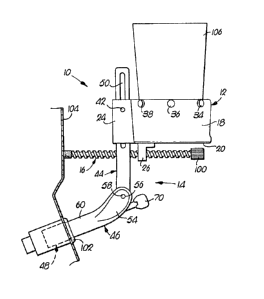
The beverage receptacle holder 10 broadly
includes receiver 12, positioning member 14, and
stabilizing element 16.
Receiver 12 includes cylindrical sidewall 18,
circular bottom wall 20 attached to the lower end
of sidewall 18, brackets 22 and 24 and stabilizing
ear 26. Walls 18 and 20, brackets 22 and 24, and
ear 26 are preferably composed of one-piece molded
plastic.
Brackets 22,24 are each L-shaped and are
mounted to the exterior of sidewall 18 with their
1269~363
1 long axes parallel to one another, with the legs
of the "L" facing one another. Brackets 22,24 are
spaced apart, and the short leg of the "L" is
remote from sidewall 18. Brackets 22,24 are able to flex slightly toward and away from one another.
Receiver 12 also includes a clamp bolt 40
having a threaded end 42. Coaxial holes (not
shown) in the sides of brackets 22 and 24 receive
clamp bolt 40. The hole in bracket 24 is threaded
0 to receive threaded end 42 of clamp bolt 40.
Stabilizing ear 26 depends from the bottom
wall 20 and includes an internally threaded hole
defined therethrough (not shown) the axis of which
is normal to the axis of sidewall 18.
Receiver 12 also includes flexible, cylindri-
cal, detachable fingers 28, 30, 32, 34, 36 and 38,
which are spaced apart and extend radially in-
wardly through sidewall 18 adjacent the normally
upper edge thereof. Each finger 28-38 includes a
2 circumferentially inscribed slot defined therein
which engages the walls of corresponding holes
defined in sidewall 18. Fingers 28-38 are best
shown in Fig. 3.
Positioning member 14 includes adjustment
structure 44, support structure 46, and socket
locking assembly 48. Adjustment structure 44 is
rectangular in cross section and includes an
elongated adjustment slot 50 parallel to the long
axis thereof. The end of adjustment structure 44
which includes slot 50 is slidably received be-
tween brackets 22,24 so that clamp bolt 40 extends
through slot 50. The end of adjustment structure
44 remote from slot 50 has a pivot hole (not
shown) for receiving a pivot clamp screw 58.
1.2~9963
1 Support structure 46 includes flat, elon-
gated, arcuate end 54 having a threaded clamp
screw receiving hole 56 therethrough which thread-
ably receives the threaded end of pivot clamp
screw 58. Pivot clamp screw 58 also extends
through the pivot hole in the end of adjustment
structure 44 thereby pivotally coupling structures
44 and 46. Cylindrical end 60 of structure 46
includes an axial hole 62 therethrough. End 60
and opposite end 54 of structure 46 are so coupled
that the body of end 54 is offset from axial hole
62. Tip 64 of end 60 is circumferentially beveled
as best shown in Fig. 6.
Socket locking assembly 48 includes expansion
member 66, expander plug 68, and tension bolt 70.
Expansion member 66 is comprised of a cylindrical
body 72 having internal frustoconical surfaces in
opposite ends thereof as shown in Fig. 6. The
outer end or body 72 has perpendicular slots 74
and 76 through the longitudinal axis of the cylin-
drical body 72. The inner end of cylindrical body
72 also has similar slots 78 and 80 that are
rotationly offset from slots 74 and 76 as shown in
Figs. 4 and 7. The slots 74,76 and 78,80 extend
approximately two-thirds the length of the cylin-
drical body 72 from their respective ends. The
areas of the cylindrical body 72 between the slots
74,76 and 78,80 form a plurality of expansion
areas 88,90 respectively. Each expansion area
88,90 has a cylindrical outer surface and a coni-
cal area on its inner surface.
The expansion member 66, as described above,
matingly receives the tip 64 of cylindrical end 60
of support structure 46.
-` 1269963
1 Frustoconically shaped expander plug 68
includes threaded axial hole 92 therethrough.
Expander plug 68 is matingly received in the end
of expansion member 66 opposed to tip 64 so that
threaded axial hole 92 and central axial hole 62
are aligned.
Tension bolt 70 includes larger diameter end
94, which diameter is larger than diameter of
central axial hole 62, and threaded smaller di-
ameter end 96. Smaller diameter end 96 is re-
ceived through central axial hole 62 and thread-
ingly received in threaded axial hole 92 of ex-
pander plug 68.
Expander plug 68 includes an integral tab 98
on its frustoconical surface radially extending
and parallel to the axis thereof. Tab 98 is
slidably received in slot 74 of expansion member
66.
Stabilizing element 16 is a threaded, elon-
gate rod which is threadably received through ear
26. One end of element 16 includes knob 100, and
the opposite end receives a resilient, surface-
engaging bumper.
To attach holder 10 to the interior of a car,
the user first removes the cigarette lighter from
the dashboard of the vehicle leaving the open
socket 102 thereby exposed. The user then inserts
socket-locking assembly 48 into socket 102.
The user then rotates tension bolt 70 clock-
wise which causes expander plug 68 to move axially
toward end 94 of tension bolt 70. Further rota-
tion of tension bolt 70 causes expansion member 66
to be compressed between tip 64 and plug 68. This
compression causes expansion areas 88,90 to move
outwardly by virtue of the sliding, frustoconical
1269963
-
surfaces of tip 64 and plug 68. As expansion
areas 88,90 move outwardly, they eventually abut
the walls of socket 102 to thereby firmly seat
socket-locking assembly 48 within socket 102 which
also firmly positions support structure 46.
The user next rotates adjustment structure 44
about pivot clamp screw 58 until structure 44 is
vertically oriented and then rotates pivot clamp
screw 58 clockwise whereby the threads on the end
of pivot c]amp screw 58 engage the threads of
receiving hole 56 and cause support structure 46
and adjustment structure 44 to firmly abut one
another to prevent further rotational movement
about pivot clamp screw 58.
The user then slides receiver 12 up or down
along slot 50 of adjustment structure 44 to locate
receiver 12 at a convenient height. Clamp bolt 40
is then turned clockwise which, by virtue of the
threads on end 42 engaging the threaded hole of
bracket 24, causes the two brackets to "squeeze"
adjustment structure therebetween to hold receiver
12 in desired position.
Knob 100 of stabilizing element 16 is then
rotated clockwise until the bumper end of element
16, remote from knob 100, snugly abuts a vertical
surface of the vehicle dashboard 104.
With holder 10 thus installed, receiver 12 is
held firmly in place by the junction of element 16
with ear 26, the junction of adjustment structure
44 with brackets 22,24, and the junction of
30 socket-locking assembly 48 with socket 102.
The user is now free to insert a beverage
receptacle 106 into recéiver 12. As receptacle
106 is placed, fingers 28-38 bend downwardly to
allow the placement of receptacle 106. However,
12~9~6~
fingers 28-38, while flexible, do offer resis-
1 tance, which resistance inhibits movement of
receptacle 106 along the plane of bottom wall 20.
Fingers 28-38 extend inwardly far enough to engage
the sides of any receptacle 106 commonly used,
such as a coffee cup, soft drink can, tumbler, or
soft drink bottle. The handle of a coffee cup may
be received within a slot formed in sidewall 18 as
shown in Fig. 2.
In nearly all vehicles equipped with a cigar-
ette lighter, the cigarette lighter is located
convenient to the driver or other front seatpassenger. The position of holder 10 is even more
convenient because the height can be adjusted to
suit the convenience of the user and receiver 12
stands apart and in front of dashboard 104.
In some motor vehicles, the cigarette lighter
socket is located very low relative to the top of
dashboard 104. With such socket 102 locations, it
may be desirable to lengthen support structure 46
to enable to installation of holder 10 to present
receiver 12 in a more convenient location. For
such installations, an "extension set" (Fig. 5) is
provided which includes extension unit 108 and
extension bolt 110. Cylindrical extension unit
108 includes central axial hole 112 therethrough.
One end of unit 108 has an inverted, frustoconical
shape adapted to matingly receive tip 64. The
other end of unit 108 is beveled the same as tip
64. Bolt 110 is identical to bolt 70 except that
bolt 110 has an additional length equal to the
length of unit 108.
In the use of the extension set, unit 108 is
placed between tip 64 and expansion member 66 and
thereby functions as an extension of end 60. Bolt
`- 12~9~63
110 replaces bolt 70 and is used in the same
1 manner. With the extension set, support structure
46 is effectively lengthened so that holder 10 can
be effectively used with remotely located cigar-
ette lighter sockets.
One skilled in the art will appreciate that
many variations in the structure and materials
described herein are possible and which still fall
within the contemplation of the present invention.
For example, the preferred embodiment uses molded,
one-piece plastic to form sidewall 18, bottom wall
20, brackets 22,24, and ear 26. These components
could be formed separately and joined together or
the entire grouping formed entirely of metal as
might be a designer's choice. Additionally, for
example, clamp bolt 40 causes brackets 22,24 to
secure support structure 44 therebetween; an
adjustable ratchet mechanism could be used to
maintain the adjusted height of receiver 12 in-
stead of the specific mechanical linkage herein
described.
Having described the preferred embodiment ofthe present invention, what is claimed and desired
to be secured by Letters Patent is:
--10--