Note: Descriptions are shown in the official language in which they were submitted.
Ii i270012
!
ROTATING PLAYGROUND EQUlPMEN r ASS~.~qBLY
' Back~round of the Invention
his invention relates to plsyground, schoo] and park equipment and more
~i particularly to rotating playground equipment such as user-propelled merry-go-rounds,
j; or "whirls".
In the prior art, there have been develop~d numerous styles and designs of
¦I whirls. These typically have a circular occupant-supporting platform positioned a
j distance above the ground either level or at a slight angle and of large enough
¦I dimensions to support two or more children. They typically have handles or handholds
¦¦ which the user can grasp as he runs on the ground around the support platform thereby
rotating the platform about its vertical axis. ~ihen the platform reaches the desired
rotational speed, the user can then hop onto the platform and together with the other
occupants is propelled around with it. Alternatively, the platform can be mounted at
1 an sngle flnd the whirl caused to turn in both a circular and a vertical motion by the
I occupant merely shifting his weight while seated in its tub shape. Another variation
j is the so-called "Pull-A-Round" device wherein one child or a group of children can
turn the platform by pulling on a stationary center wheel.
These whirls have given pleasure to children for many years. However, problems
! are present in that the whirls can be csused to turn at too great a speed. This can
¦ happen when a plurality of athletic children are simultaneously propelling the machine
!l or when one or more very strong children or teenagers are propelling it. This can
¦I be dangerous in that the children may be propelled off of the platform by its centrifugal
I, force or, when trying to disembark while it is rotating, they may be injured. ~urther,
¦, the speeds may be so great that the children are frightened. Also, recent designs
¦, have been so efficient that the whirl will continue to turn for unduly great lengths
j' of time. The children occupants can become frustrated or scsred as they cannot
Il disembark for many minutes. Also, the unreasonably long self-rotation period results
¦' in longer rotating sessions for each group of children, which mesns that fewer children
¦ can en30y the whirl since the waiting time is longer.
Accordingly, it is the principal object of the present invention to provide an
¦~ improved piece of rotating playground eguipment.
!
1,
I . ,
,
1270012
1,
j, Another object of the present invention is to provide an improved design of
¦ rotflting pl~ygr~und equipment whi~h is safer and helps prevent accidents.
I' A further object Or the present invention is to provide an improved piece of
h rot~ting pl~yground equipment including mesns for limiting its turning speed.
A still further object of the present invention is to provide an improved piece
¦ of rotating playground equipment which includes meRns for increasing the effort required
j to turn the unit.
t Another object is to provide ~ novel piece of rotating playground equipment
j that includes a means for rapidly slowing the rotation of the unit after the rotating
¦ forces have ceased.
Other objects and advantages of the present invention will beeome more apparent
' to those persons having ordinary skill in the art to which the present invention pertsins
from the following deseription taken in conjunction with the accompanying drawings.
t
Brief Description of the Drawin~s
Figure 1 is a fragmentary top plan view of one embodiment of the present
, invention for a rotating playground equipment assembly.
Figure 2 is a fragmentary side elevational view of the assembly of Figure 1.
Figure 3 is a eross-sectionsl view taken along line 3-3 of Figure 1.
Figure 4 is a fragmentary top plan view of 8 second embodiment of the present
¦ invention.
¦~ Figure 5 is a cross-sectional view taken along line 5-5 of Figure 4. ¦
!~ Figure 6 is n fragmentary side elevational view of a third embodiment of the
!,''presentinvention. I
.c
. .
. ' !
!' ~2~0012
.,
¦, Detailed Descriptions oS the Preferred Embodiments
¦I Referring to the drawings, it is seen that Figures l through 3 illustrate a first
ilembodiment of the present invention wherein a mechanical type of brake is employed
¦,on the rotating playground equipment assembly, Figures 4 and 5 illustrate a second,
!embodiment of the present invention wherein a hydraulic brake is employed, and Figure
j,6 illustrates a variation on the second embodiment wherein a chain-type connection is
i provided for the hydraulic brake.
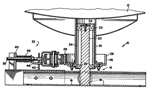
i I Referring to Figures 2 snd 3, it is seen that the present piece of rotating
¦¦playground equipment assembly shown generally at 10 comprises a whirl platform
! assembly 12 which is generally circular in its top plan view and is configured and
',dimensioned to support one or more occupants. A soft, resilient surface, not concrete
or asphalt, should be placed under whirl platform assembly 12, extending at least six
feet in all directions. Whirl platform assembly 12 can include suitable handles (not
' shown) and a dimpled slip resistant surface (not shown). A whirl hub 14 is secured to
j the lower portion of whirl platform sssembly 12, extends downward therefrom, and
nforms the lower part thereof. As has been shown in Pigure 3, hub 14 has an upright
hollow cylindrical shape. A base assembly, shown best in Figure 1 generally at 16,
supports the entire assembly 10, and includes four horizontal r~dial support legs 18.
Secured firmly to the legs 18 and extending up from their center is the spindle 20,
which as best shown in Figure 3, extends up through hollow hub 14. Hub 14 rotates
I, about spindle 20 on bearings 22 positioned therebetween. Suitable structure 24 is
¦~provided to keep bearings 22 in place between hub 14 and spindle 20. An outer hub
,wheel 26 is secured to the outside of the lower end of the whirl hub 14. In top plan
view, it has a circular configuration defined by its outer vertical edge 28.
A pressure wheel 30 is mounted by a pressure wheel mounting assembly shown
j' generally at 32 for rotation about a vertical axis and so that it applies constant
jifrictional pressure against edge 28. The pressure wheel 30 can be made from a gray
¦ iron casting with a urethane tire on its outside surface. Pressure wheel mounting
assembly 32 includes aisupport yoke 34 having a vertically disposed pin 36 which passes
through pressure wheel 30 and supports the wheel. A horizontal bar 38 is attached at
, one end to yoke 34 and passes through openings in upright supports or stanchions 40
~3~
12700~2
'
and 42. I)pright supports 40, 42 are firmly secured to the top of one of the radisl
support legs 18. Also attached to yoke 34 is a lower bar 46 passing through a second
lower opening in upright support 42. This lower b~r 46 which is spaced directly below
horizontal bar 38 prevents the rotation of support yoke 34 8bout the long;tudina] axis
Or horizontHI b~r 38. A compression spring 48 surrounds horizontal bar 38 and biases
sgsinst upright support 40 snd sn sdjustsble nut 50, which is thteaded on threads 52
on horizontal bar 38. Compression spring 48 forces against the adjustHble nut 50
urging pressure wheel 30 8g8inst the outer hub wheel ed~e 28. This csuses a rolling
frictional contact between the two wheels thereby exerting a constant braking or load
on the rotstion of whirl plstrorm assembly 12. This crestes sn increasing physiicsl
etfort needed to turn as one tries to go faster. It iurther limits the high centrifugal
forces produced st the rlm of the whirl platform assembly 12. Horizontal ba~ 38 is
. . ,
provided with thresds 52 along which adjustable nut 50 csn be thresded to va;y the
pressure compression spring 48 exerts on pressure wheel 30. The spring can be of
any 8uitsble size, for exsmple, an 11/16 inch inner dismeter by a 1 1/4 inch outer
dismeter by a 3 inch length rectangulsr wire construction csn be used such as thst
manutactured by Danb Machine Corporation of Olive Brsnch, Missiissippi. The brake
Is rully enclosed and concesled in a whirl base housing or shield 53, best shown in
Pigure 2.
Pigures 4 and 5 illustrate a second embodiment of the present invention using
a hydraulic braking system, which i5 shown generally at 54. This rotating plsyground
equipment assembly 56 inclu*s a similsr whirl platform assembly 58 and a whirl hub
60 mounted thereto and a part thereof. Suitable brscing members 62 are connected
at the lower end of hub 60 and to the outer ends of whirl platform assembly 58. The
support base 64 having four radial support legs 66 similarly supports the spindle 68 in
the middle thereof. Bearings 70 are positioned between spindle 68 and the interior of
the whirl hub 60 and the whirl hub rotates about and on these besrings. Suitable
structure 72 is provided to keep bearings 70 in position therebetween. A drive gear 74
is secured via bolts 75 to the lower end of the hub 60 and it has teeth 74a which
engage with the teeth 76a of the driven Bear 76, which comprises part of hydraulic
braking system 54. Driven gear 76 in turn drives the hydraulic pump assembly shown
.:
i.2700i.2
generally at 78 through its hydr8ulic pump drive shaft 80. Hydraulic pump assembly 78
I; is also mounted to one o~ radial support le~s 66. Rotation of driven gear 76 drives
i the hydraulic pump which has been preset to creste a load against the rotation of
drive gear 74 thereby effectively controlling the speed that whirl platform assembly
I' 58 csn be rotated. The load iS created by fixed capacity v81ves 82, 83 with 3/4 quart
j cspacity reservoir 84 providing hydraulic fluid to the closed System. The pump 86 of
hydr8ulic pump 8ssembly 78 iS bi-directional with valves 82, 83 free flow in one
! direction and restricting the flnw of fluid in the opposite direction.
, Hydraulic braking system 54 is a true speed limiter in that only so much oil can
¦ be pushed through the restricting valves 82, 83 in one direction. Pump 86 iS capable
~, of moving only So much oil and any attempt to rotate f8ster causes fluid by-pass
i within the pump. The system is closed since the pump 86 is bi-directional and-valves
82, 83 8re loaded in one direction and free flow in the other. This unit, as well 8s
the mechanical brake previously described, provide a rapid slowing of rotation after
¦ the rot8ting forces have ceased. It is 8nticipated that hydraulic braking system 54
will be set to limit the rotation of the whirl platform 8ssembly 58 to about thirty
~l' revolutions per minute, 8nd will effectively stop the rotation in about 3 revolutions.
j! The hydraulic pump 8ssembly iS a closed hydraulic system, and the lines 88, 89 to 8nd
~ from reservoir 84 8re positioned at a suitable level below the top of the oil level to
j prevent 8ir from entering the system. As previously described, rotation of the drive
.' ge8r 74 fixed to the whirl drives the driven gear 76 fixed to the pump shaft 80.
j, Pump rotstion in one direction pUlls oil from the reservoir through one line in the
¦- direction shown through the free now side of the valves. The pump moves the oil
i out through the pressure side of the v81ves 82, 83 8nd the other line in the direction
~', shown 8nd returns it to the reservoir 84. The pump is bi-direction~l so thst reversal
of rot8tion reverses the 8ction through lines 88 8nd 89. The pump can be any suitable
I, pump such 8s that manufactured by ADM Model No. ADM50-4, 8nd vslves 82, 83 Can, I
,i be 8ny suitable valves such 8s th8t m8nuf8ctured by P8rker H8nnifin, Model No. F6005-
1 (with 8 one pound spring). As the rot8tion81 speed increases, the pressure approaches
~ the pressure c8pacity snd/or the g811Ons per minute flow capabilitv of the valve, which
¦~ precludes faster rot8tion 8nd the oil then recircul8tes within the pump. A suitable
, shield or housing 90 enclosing the hydr8ulic br8king system 54 is provided for safety
:
' ~ ~
~2'700~2
purposes ss well as to pPevent the influx of dirt, stone and other particles into the
system .
The rotsting pl~yground equipment sssembly shown generally st 92 of Figure 6
shows an alternative to that of Figures 4 snd 5 snd provides a chsin drive connection
94 between the drive gesr 96 and the driven gear or sprocket 98 as opposed to the
direct gear teeth connections 75a and 76A. Assemblies 56 and 92 are designed with
their pump construction to have no parts that can wear out. It is expected though
that assembly 56 will be chesper and easier to maintain thsn assembly 92. Assembly
92 similar to assembly 56 limits the speed at which the assembly can turn and more
rapidly slows the rotation once the rotating forces have ceased mal~ing for a safer;
and more enjoyable rotating pla~ground equipment assembly or whirl.
From the foregoing detailed description, it will be evident that there are a
number of changes, sdaptations, snd modifications of the present invention which come
within the province of those persons having ordinary skill in the art to which the
aforementioned invention pertains. However, it is intended that all such variations
not departing from the spirit of the invention be considered as within the scope thereof
as limited solely by the appended claims.