Note: Descriptions are shown in the official language in which they were submitted.
~7~
The present lnvention relates to an anti-wear yuiding
device for primary suspensions of railway bogies.
It is known that one o~ the most important problems in
railway vehicles, is that of improving the running comfort to an
extent as high as possible.
The method normally used to the purpose of achieving
such a result is O:e carrying out a good maintenance of the track
and of providing bogies with primary and secondary suspensions
with suitable features.
Notwithstanding the adoption of these measures of main-
tenance and design character, the running quality level, espe-
cially on the tracks of lower class, is not always saklsfactoryand, abovs all, it can be irnproved only seldom, although -the sus-
pensions are provided with intrinsic andJor additional systems
and/or devices which are very complex. These devices or systems
are, however, expensive, and not always reliable.
The present invention provldes an anti-wear guiding
device for primary suspPnsion of railway bogies, which is of
simple structure and which can be easily applied, and is directly
installable between the track, which is the origin po1nt of any
perturbations, and the primary SuSpensiOQ of the bogie, so as to
improve the funning quality of the railway vehicleO
In accordance with the present lnvention there ls pro-
vided a railway bogie in which each wheel has an axle mounted in
a bearing in a sleeve m0mber which is directly coupled to the
bogie frame through primary suspension units which allow vibra-
tion of the sleeve member relative to the frame in a horizontal
plane, each primary suspension unlt comprising a resilient member
sandwiched between a f~rst housing element fixed to the bogie
frame and a second housing element fixed to the sleeve member,
wherein between the sleeve member and at least one ad~arent first
.~ ~
. : ,
r;~L
housing element a gulde body is replaceably mounted, the guide
body being shaped and positioned to provide ]onyitudinal and
transverse clearances between the first housing element and khe
sleeve member which allows movement in a vertical direction but
limits movement in the lonyitudina:L and transverse directions in
the horizontal plane.
A device according to the invention increases, in the
horizontal plane, the value of the attenuation coef~icient and
hence the value of the running ~ua]Lity in a very efflcaciou~ way,
in that it acts directly a-t the level of the source of the vibra-
tions, in addition to acting on the accelerations in the horizon-
tal plane which are more tiriny for the passengers.
Together with this, a device according ko the invention
allows an optimum runnlng quality to be achieved by means of
suitable successive and easy optimizing modifications. These can
be advantageously made on prototype bogies, it being not neces-
sary to stop the standard mass production, measuring the acceler-
ations in the horizontal plane during test trips on the track,
and hence modifying the device in function of the real character-
istics of the track.
The invention will be described herainunder in more
detail, on the basis of a preferred practical embodiment~ which
is shown in the drawing attach~d, which represents for exemplify-
ing purposes the portion of a railway bogie comprising the pri-
mary suspension, in correspondence o~ which the device is in-
stalled, which is the object of the invention. In particular:-
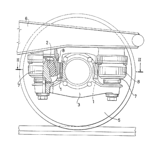
Fig. 1 is an elevational view of said part, and
Fig. 2 shows a section along the line II-II of Fig. lo
The illustrated portion of the bogie is essential-
~ ~2'7~3~5~
ly ~ormed by the spring 2, by the sleeve 3, by the bear
ings 4, by the wheel 5, by the side member of the ~rame
6.
~he spring 2, shown in the drawing, i8 of known type,
of rubber. It performs all required functions: the fun-
ction o~ elastically suspending the vertical load, and
that of elastically transTnitting a~1 the forces actine
on the horizontal plane, bet~een the sleeve 3 and -the
~rame of the bogie 6.
~0 The spring 2 of rubber may be o~ the cone fruetum
shaped type, housed and rotatin~ within the metal hous
ings 7 and 8, or of the cone frustum shaped ring type,
cured onto the said metal parts.
The sprin~ 2 may also be o~ another known type, not
shown in the drawing, in which the function of suspend
ing elastically the vertical load and -the function of
transmitting elastically the forces in the horizontal
plane are separatedO In this case7 the ver-tical load
i5 elastically suspended by means of a rubber spring
of the sin~le disc, or o~ the multiple disc type, or
by means of a steel helical spring, whilst the ~orce~
acting in the horizontal plane are transmitted by a
rubber ring freely rota-ting within a cylindrical sur-
~ace metal seat3
In all these typical applications, it can be seen
that the freedom degree o~ the primary suspenslon in
the horizontal plane is controlled by the el~stic char
acteristic in that plane of the rubber ring.
This characteristic~, after that the design has
been flnished, cannot be suitably varied any longer~
nor can it be adapted and optimized in the known bogies,
~ 3~
as a function o~ the type of the track and o~ the type
of the vehiole.
In order to obviate thi~ drawback, the device i~
provided according to the invention, which i~ indicated
in the drawin~ with 1.
Said device is formed by a guiding body 1, made of
an an-ti-wear material with suitable re~ilience, and po
aitioned in a de-tachable way between the ~leeve 3 end
the metal element 8 (containing the spring 2), solid
with the side member 6 of the frame of the boKie. The
guiding body 1 has vertical anti-wear surfaces on lon-
gitudinal and tran~versal planes in the contact area
between the sleeve 3 and the element 8. It acts thus as
a transversal end longitudinal guiding element between
the sleeve 3 (and hence the wheel 5) and the part 8
(and hence the side member 6 of the frame of the bogie)D
hdvantageously, -two bod-ies 1 are provided, posi-
tioned symmetrically on opposite sides of the axle of
the wheel 5.
By suitably varying the thickness of -the body or
of the bodies 1, the value can be varied of the clear
ance between the sleeve 3 and the side member 6 of the
bogie1 in a longitu~inal direction as well as in a trans
versal direction~ equally or differently, end on the
basis of the acceleration measurements above mentioned.
~he variation of the clearance produces a variation
of the respon~e, as for frequency as well as for am-
plitude, of the primary suspension in the horizontal
plane. I-t is there~ore possible to deterrnine, during
the tests on the field~ the optimum value o~ the same
clearance, for which, in the cornplex multi-mass dynam
~ 7~15~
ic phenomenon being con~idered, in function of the ir-
regularities of the track and of the running ~peeds of
the vehicle, the minimum value are produced of the ac-
celerations~ and i~ consequently possible to install the
device 1 of the most suitable measure for obtaining an
optimum behaviour and running comfort o~ the vehicle
along the whole path.
The body 1, which advantageously has its cross sec
tion o~ U shape, can be fixed on the sleeve ~, as it i~
shown in the drawing, or to the element 8 solid with the
frame of the bogie.
As it can be under~tood from what described, the de
vice according -to the invention can be easily in~talled
in any type of primary ~uspension, of existing type,
15 or of new type, with springs made of steel and~ or of
rubber.
- . ,. .
- . ,