Note: Descriptions are shown in the official language in which they were submitted.
~7~ i3
B~CKGROUND OF THE INVENTION
I Field of the Inven-tiorl: This invention relates
generally to seed planting apparatus, and more particularly to an
improved plan-ter which may be used to accurately and precisely
position a crop seed into -the ground at a spacing which can be
readily adjusted in a first embodiment, within limits, by the
simple adJustment of a pu]ley size, and in a second embodimen-t by
the adjustment of a hydrau:Lic flow con-trol valve.
II. Discuss:ion Oe -the Prior Art: In the Adams Patent
3,5~1,380, there is described a seed planter which incorporates
an endless belt as a conveyor, the belt having a plurality of
openings call "seed pockets" formed therealong for receiving
individual seeds from a hopper and for carrying those seeds to a
location where the conveyor belt engages the ground. Ideally~
the conveyor belt is driven so that the ground-engaging flight is
moving in a direction opposite to the direction of movement of
the seed plan-ter and a-t the same relatiYe velocity so that -the
effective ground speed of the conveyor is zero. Associated with
the conveyor belt is a further belt having protuberances thereon
at a spacing corresponding to the spacing between the pockets on
the belt. The pro-tuberances are configured to enter the openings
forming the seed pockets and -to force the seeds there~rom into
the ground.
While, in theory, -the device described in the
Adams '380 patent may appear operable, in practice, a device made
in accordance with this patent would be of limited operabili$y.
First of all, the manner in which the hopper is positioned
relative to the seed-receiving belt necessarily
'~
~ ~70~S;~
limits the capacity of the hopper. Accordingly, it is necessary to refill
the hopper at more frequent intervals than would otherwiseA be re4uired.
Also, practical difficulties are encoun-tered in loading the seed pockets in
the belt from the hopper and in unloacling same when it is considered that
the conveyor belt must be moving at the vehicle's ~round speecl to
maintain the necessary zero rela-tive motion between ground and the belt.
The system of the Adams '380 patent also suffers from the defect in that
the spacing between adjacent seeds c:annot be controlled and is strictly
limited to the spacing between seed openings on the belt itself. As such,
the device of the Adarns patent canno-t be used to plant rnore than one
comrnodlty if those commodltics require diffcrent seed-to-seed spacin~,.
SUMMA~Y OF THE INVENTION
My invention, while somewhat similar in concept to the
apparatùs disclosed in the Adams patent, overcomes most of the
drawbacks of the prior art. In accordance with a firs-~ embodiment of my
invention, i provide a first or main frame which is supported by a pair of
rear dual wheels and a secondary frame which is pivotally coupled to the
axle on which the pair of dual wheels are journaled. Affixed to the upper
side of the secondary frame are left and right seed hoppers, which are
generally rectan~ular boxes but which have bottoms which slope to an
elongated gap or seed orifice near the rniddle thereof. Also supported by
the secondary frame is a iurther axle upon which a ground-engaging wheel
is affixed. Mounted on this same axle is a pulley which may have
adjustable sheaves for effectively varying the dlameter of that pulley. An
~5 endless belt joins that pulley to a further pulley mounted on an idler shaft9
and affixed to that idler shaft are first and second sprocket wheels which
are generally ali~ned with the longitudinal orifice in ~he sloped bottoms of
the seed hoppers. 30ined to the underside of the secondary frame are
downwardly depending bearing plates which support disk-like colters
which, when dtagged over the ground, will dig a trench of a predetermined
de,oth. An endless chain passes over tl-e sprockets on the idler shaft, and
attached to predeCertnined links of that endless chain are specially
designed seed pockets which are capable of receiving only one seed in
each pocket as it passes benea-th the see~l orifice in the bottom of the
hopper. As the endless chain orbits, the seed will be carried to a
discharge point just above the ground where it will fall free from the
pocket and into the furrow formed by tlle col~r. As the vehicle continucs
to move, the dual rear tires are so positioned that they will effectively
close the furrow over the deposited seeds. In that the seed conveyin~
chain does not contact the ground, it is not a requirernent that it tnove at
the appropriate speed to create zero relative velocity between the
conveyor and the ground as in the Adams patent. Hence, it is possible
that by adjusting the relative diameters of -the pulleys on the drive shaft
and the idler shaft, the seed may be dropped at locations other than those
dictated by the spacing between the seed receiving pockets on the chain.
ay having more than one chain1 each with its own especi~lly dirnensioned
seed pockets, the planter of the present invention can be used to plant a
varie~y of row crops by merely substitutin~ chains.
A hydraulic actuator is suitably disposed between the main
frame and the secondary pivoting frame so that, when actuated, the
secondary frarne pivots about the axle of the dual wheels as a fulcrum and
elevates the colters and the conveyor chain drive wheel from the ground.
Thus, upon reachin~ the end of a row, the farmer can merely operate tlle
hydraulic cylinder ~o raise the colters and siop the seed flow. Lil<ewise,
when drivin~ over a highway to or from the planting site, the colters and
conveyor chain drive wheel are maintained in their elevated and stopped
position.
Also ~escribed herein is an alternative embodiment of my
invention. In this alternative embodiment, a constant torque hydraulic
motor is used to cause rotation of the endless chain which carries seed
rom the hopper to the discharge point which is just above the ground.
The speed at which the constant torque hydraulic motor is driven can he
varied by ac~uating a contrcl flow valve. In this ~Iternative ernbodilnent,
an rpm counter and a digital display perrnit the user to control the
discharge rate of the seed. By loc:ating the control flow valve and the
digital readout in the cab in the tractor, the operator can fuJly controI the
rate at which seed is dischargcd frorn the cab.
OBJEC TS
Accordin~ly, it is the principal object of the present Invention to
provide a new and improved seed planting apparatus.
Anoth~r object of the invention is to provide a sced planting
apparatus in which the spacing between seeds being planted can be readily
adjusted.
Another object of the invention is to provide a seed planter in
which the capacity of the seed hoppers is not limited by the physical
disposition of the seed conveying belt associated therewith.
A still further object of the invention is to provide a seed planter
of the type involving an endless conveyor chain for transporting seeds
from a supply hopper to a desired location close to the ground but in
which the conveyor does not actually physically contact the ground.
A further object o~ the invention is to provide a seed planter in
which the flow of seed and the digging of furrows for the seed can be
readily con~rolled.
These and other objec~s and advantages of ~he invention will
become apparent to those skilled in the art from the following detailed
description of a preferred embodiment, especially when considered in
conjunction with the accompanying drawings in which like numerals in the
several views refer to corresponding par~s.
DESCRIPTION OF THE DRAWINGS
Figure I is a perspective view of the preferred embodiment;
7~5~
Figure 2 is a top plan view of the embodimcnt of Figure l;
Figure 3 is a front view of the preferred ernbodiment of
Figure l;
Figure 4 is a side elevation view showing the secondary frame in
its raised and lowered positions;
Figure 5 is a partial side sectional view taken along the lines 5-5
in Figure 2;
Figure 6 is a sectional view takcn along the lines 6 6 in Figure ~;
Figure 7 is a fragmentary view of the seed conveyor chain;
Figure 8 is an enlarged view of a seed pocket of the type
attached to the conveyor chain of Figure 7 for handling seed corn;
Figures 9 and 10 are views showing an alternative means for
driving the seed conveyor chain.
DESCRlPTIC)N OF A PREFERRED EMBODIMENT
Certain terminology will be used in the following description for
convenience in reference only and should not be construed as limiting.
The words "upwardly", "downwardly"~ "rightwardly" and "leftwardly" will
refer to directions in the drawings to which reference is made. The words
"inwardly" and "outwardly" will refer to directions toward and away from,
respectively, the geometric center of the device and associated parts
thereof. This terminology is intended to include the words speciEically
mentioned above, derivatives thereof as weJI as words of similar lmport.
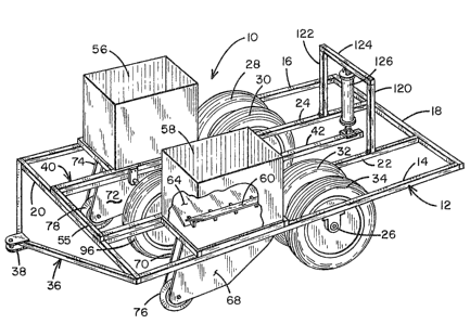
Referring first to Figure l there is indicated generally by
numeraJ lû a seed planter comprising a first preferred embodiment of the
present invention. The planter 10 includes a maln frame member
indicated generally by numeral 12 which is preferably formed from steel
tubing and which includes Jeft and right side members 14 and 16, a rear
end member 18, a front end member 20 and two intermediatej spaced-
apart, Jongitudinally-extendin$ braces 22 and 24. Extending transversely
3~ to the frame members 14 and 1~ is an axle 26 on which first and secondsets of dual rear wheels ~8-30 and 32-34 are ~ournaJed for rotation.
. -:
70~
A yoke assembly 36 is welded to the Eront end mernber 20 and at
the center thereof is a clevis 38 by which the planter assembly 10 can be
fastened to a towing vehicle by rneans of a hitch pin ~not shown).
Resting atop the main frame 12 is a secondary frame, which is
indicated generally by numeral 1~0, and which has a longitudinal bar
member 42 extending lengthwise approximately along the mid-line axis of
the planter ~rame. The bar member 42 has a bearing housin~ 44 welcled
thereto and passing through the bearing housing l~4 is the axle mernber 26.
As such, the member 42 of the secondary frame can be rocked or pivoted
about the axle 26 as ~ fulcrurn. Welded to the mernber 42 is a
transversely extending bar 46 of a length so that the end portions thereof
rest atop the side mernbers 14 and 16 comprising the lower frame 12.
Welded to and projecting forwardly frorn the transversely extending
bar 46 are frame rnembers 48 and 50 which respectively overlay the
intermediate support braces 22 and 24 of the lower main frame 12. For
the purposes of adding rigidity to the secondary frame, further cross
members 52 and 54 are welded or otherwise affixed to the upper or
seconclary frame 40. A cross-strut 55 extends between the forward ends
of longitudinal frame members 48 and 50 and rests upon leveling jack-
screws 57 (Fi~ure 4). The jack-screws allow limited height adjustment of
the colters whereby the depth of the furrow being dug can be set.
A pair of seed hoppers 56 and 58 are attached to the secondary
frame and are supported by the cross member 46 and the reinforcing bars
52 and 54, all as can best be observed in the plan view of Figure 2. The
seed boxes 56 and 58 may be generally rectangular in their configuration
but the bottom walls thereof are sloped downwardly from their side edges
towards the centerline of the hoppers. As sho~n in Figures 1 and 6, a
first bottom deiEining plate 60 Is spaced vertically at its end 62 from the
end of the other bottom-defining plate 64. The end 62, however, overlaps
the end of the bottom segment 64 and defines a generally longitudinal
~'7~
slit 66 through which the seed kernels may pass. A plurality of spacer
elements are used to maintain the plate separa~ion defining the slit 66.
f\ttached to the underside of the secondary frame and berIeath
each of the hoppers 56 and 58 are two parallel, spaced-apart bearing
plates 68-70 and 72-74. These sets of bearing plates project downwardly
toward the ground and at the lower forward edge thereof are bearings in
which disks or colters 76 and 78 are journaled. The bearing plates are
positioned such that the colters 76 ancl 78 are longitudinally aligned with
the spacing betweeIl the dual rear tires 28-30 and 32-34 and ~enerally
with the longitudinal slit 66 in the bottoms of the hoppers.
By referring to Figures 5 and 6, it c~n also be seen that journaled
between the bearing plates 6~ and 70 are sprocl<et wheels 80, 82 and ~4
and idler sprocket 86. An endless chain 88 is placed over the
sprockets 80-86 to define a generally horizontal flight gO ex~ending
between sprocket wheels 80 and 82, a generally vertical flight 92
extending between sprocket wheels 82 and 84 and a generally inclined
return flight 94 extending between the sprociset wheels 84 and 80. In this
arrangement, sprocket 80 is the drive sprocket while sprocket wheels 82,
84 and 86 function as idlers to change the direction of the endless
chain 88. While only the layout of the various sprocket wheels associated
with the bearing plates 6B and 70 have been described, it is to be
understood that a sirnilar chain and sprocket assembly is journaled
between the bearin8 plates 72 and 74 as well.
In Figure 2J there is shown a further wheel 96 which is fixedly
attached to an axle 98 which is journaled for rotation in bearing
blocks 100, 102 and 104, each of which is secured to a structural member
comprising the secondary or upper frame assembly 40. When in its seed-
plan~ing modeI the wheel 96 engages the ground and as the planter 10 is
pulled by a tractor or other type of farm vehicle, the shaft 98 is driven
A pulley 106 preferably having adjustable sheaves is fixedly secured to the
~l~'7~
shaft 98 so as to rotate therewith. Also journaled for rotation in the
secondary or upper frame 40 is a driven shaft 108 upon which is attachecl
a pair of V-belt pulleys 10') and 110 of a fixed diameter and an endless V-
belt 112 surrounds the pulleys 10~ and 109 or 110 so that as the wheel 96
S i5 rotated so is the shaft 108. !~y providing two pulleys 109 and 110 of an
appropriate diameter, the belt 112 can be rnoved to obtain a different
speed ra-tio for soybeans rather than corn, for example.
Now, with reference to Figures 5 and 6, it can be observed that
the shaft 108 passes through the bearing plate 70 and has the drive
sprocket 80 fastenecJ to it with the end of the shaf t 108 being journaled in
a bearing 114 secured to the bearing plate 68. Thus, rotation of the
whecl 96 results In th~ convcyor chaln 88 bein~ dri~/en. The relutivf^ speed
at which the conveyor chain moves can, of course, be adjusted by
adjusting the relative diameters of the pulley 106.
Continuing with the description of -the constructional features of
the preferred embodiment and with particular reference to Figure 8, the
conveyor chain 8~ has secured to its outer edge a plurality of seed-
receiving pockets 116. A perspective view of one such seed pocket is
shown in Figure 8. The par~icular contour of the seed pocket has been
found to facilitate the entry and exit of a single seed of corn into each
pocket as it rotates orbitally witl) the enclless chain 8~. If the planter 10
is ts be used with other row crops, such as soybeans, then a separate chain
having seed pockets dimensional to accommodate seed soybeans would be
substituted for the chain 88 with pockets 116. The substitution is easily
accomplished by using the master link which joins the two ends of the
corn planter chain togeSher to join the end links of the corn plantin~ chain
to ~he soybean planting chain and then pulling the soybean planting chain
around the sprocket wheels. As the first chain is removed, the new chain
is substitu~e~0
The cross-sectionai view of Figure 6 perhaps best illustrates the
relative orientation of the upper horizontal flight 90 of the chain 88 ;3s it
traverses -the longitudinal slit 66 forrned in the base in the hopper 58.
Numeral 118 identifies a support rail upon which the horizontal flight 90
of the chain 88 rests and atop the chain are the seed pockets 116. The
support rail 118 prevents the flight 9û from sagging and main~ains the
seed pockets at the appropriate clevaLion relative to the slit 66 so that a
seed passing therethrough will find its way into; seed pocket 116. Once a
given seed pocket is occupied with a seed, other seeds are blocked from
entering. Thus, as the flight 90 of the chain 8~ moves along the guide
rail 118 by virtue of being driven by the sprocket 80, seeds will flow froln
the hopper and will find their way into vacant seed pockets. Because the
hopper bottom segment 60 overlaps the hopper bottom segment 64
proxinnate the gap 66, the weight of the seeds in the hopper 58 is not
applied to the seeds Elowing through the gap and they tend not to bind at
the polnt of entry into the moving seed pockets. Also, the plural spaced-
apart support elemen~s disposed between plates 6û and 64 prevent the
seed exit slot 62 from narrowing due to the weight of seed in the hopper.
Next, referring to Figures 1 and 3, it can be seen that welded to
2n the main frame 12 and specifically to the longitudinal braces 22 and 24
thereof are uprights 120 and 122 which are spanned at their upper end by
a cross-bar 124. Operatively disposed between the cross-bar 124 and the
strut 42 of the secondary frame 40 is a hydraulic actuator 126. The
actuator 126 is shown with its piston rod retracted in Fi~ure I and, with
reference to Figure 4, it can be seen that when the piston rod 128 of the
hydraulic actuator 126 is extended, it causes the secondary frame 40 to
pivot about the axle 26 to the disposition illustrated by the phantom lines
in Figure 4. In this latter disposition, the colters 76 and 78 as well as the
driving wheel 96 are elevated free of the ground~ and, accordinglyS the
conveyor chain with its seed pockets is stationary.
~7~ 3
Having described the details of the constructional fe~tures of
the invention, considera~ion will next be given to its modes of operation.
OPERATION
To begin with, the farmer will fill each of the large capacity
seed hoppers 56 and 58 with the seed to be planted and then will tow the
planter 10 to the site where the seecl is to be sewn. In route, the
hydraulic actu~tor 126 will llaYe be0n ac~uated so that the sccondary
frame assesnbly 40 and the various cornponents suspended frorn It will be
tilted as shown in Figure 4 so that the colters 76 and 78 do not engage the
ground and so that the conveyor chains clriven hy the wheel 96 and
shafts 98 and 108 do not move.
Once the location is reached where planting is to take place, the
hydraulic actuator 126 is operated to retrac-t its piston rod 128 into its
cylinder. Under this condition, the secondary f rame ls lowered to the
position represented by the solid lines in Figure 4 and to the position
reflected in the views of Figures 1 and 3 as well. Here, the wheel 96
engages the ground so that when the planter assembly is towed by a
tractor or the like, the wheei will drive the shaft 98 which~ because of the
belt/pulley coupling~ will also drive shaft 108. Rotation of the shaft 108
drlves the sprocket 80 and causes the chain 88 to rnove. ~ecause of the
manner in which the seed pockets 116 are disposed on the chain and
routed past the sllt 66 formed in the bottorn of each of the hoppers, seed
will be individually fed frorn ~he hopper through the slit into the seed
pockets. The upper flight 90 of the chain is supported at the appropriate
elevation to receive seed by means of a guide rail 118 positioned beneath
the flight 90. As the chain moves, the seeds are carried in their pockets
to vertical iElight 92 and as a seed pocket carrying a seed turns about the
sprocket 84, the seed falls free of the pocket. In that the colter 76 is
traversing the grounds in advance of the conveyor chain, it has already
created a furrow in the ground into which the seed will fall.
L5~
By using pulley 106 of adjustable diameter, it is possible to
adjust the spacing of the seed clroppecl from approxirnately four inches to
approximately ten inches. As the planter continues along its path, the
furrows formed by the colters 76 and 78 are closed ~7ver by the passage of
the dual wheels 28-30 and 32-34 following the pJacernent of the seeds in
the furrow. Thus, the seeds are totally covered and will not be consumed
by bircls or the like. Also9 the seeds will be positioned at an optimum
depth to enhance germination.
As the farmer reaches the end of a planting row, he a~;aln may
l() actuate the cylinder 126 to lif~ the colters and the drive wheel 96 frorn
the ground as he negotiates a turn prior to traversing a new row to be
plant~d. This, of course, terminates seed flow.
Because flight 90 of the chain extends generally parallel to the
bottom of the hoppers 56 and 58, those hoppers can carry a substantially
greater amount of seed than can be carried by the hoppers in the
aforereferenced Adams patent. Also, because of the manner in which the
hopper floor segment 60 overlaps the hopper floor se~ment 64 proximate
the seed exiting slit, improved seed flow results because the sceds exiting
the slo~ 66 are not subject to the pressure of the seed load contained in
the hopper. By using the orbital path for the conveyor chain ~ illustrated
in Figure 5, the seeds are carried to a point close ~o the ground before
they are dropped Into the furrow. This prevents the seed from bouncing
and being misplaced. The bearing plates 68-70 and 72-74 shield the
conveyor chain so that dirt cannot gum up the seed pockets prior to their
return to their seed-receiving disposition.
I~ecause the seed conveyor chain 8~ and the pockets carried
thereby never contact the ground, the seed planter of the presen t
invention can be towed a-t a speed sigllificantly in excess of that allowed
by prior art designs, especially the one reflected in the aforereferenced
Adams patent. This higher travel speed along with the increased hopper
70~5~
capacity allows significant s~vings in planting time over known prior art
planters.
Also, it is to be understood that while the arrangemen$ shown in
Figure 2 utilizes only two hoppers and seed feeding conveyor assemblies,
persons skllled in the art can readily de~sign a sirnilar system incorporating
additional hoppers and conveyor assernblies without departing from the
scope of the invention. Also, the foregoing description has been given
illustrating tlle inventlon in the pl~nting of corn and soybeans. It is to be
understood, however, that the system is not lirnited to those ~rains and
that with minor modiflcations, the invention can be used to plant other
seeds as well.
SECOND PREFERRED EMBODIMENT
Figures 9 and 10 are directed to an alternative preferred
embodiment. The primary difference between this alternative
embodiment and the embodiment described above ia that the seed
discharge mechanism is driven by a constant torque hydraulic motor
rather than by a wheel such as ~6 (Figure 1) which engages the ground.
Sh~wn in ~igure 9 is the constant torque hydraulic rnotor ~00.
Connected to this motor by an inlet hydraulic hose 201 and an outlet
hydraulic hose 202 is a flow control valve ~203 which is rnounted inslde the
tractor cab. Couplers 204 and 205 are associated with the hydraulic
hoses 201 and 202 to permit easy connection and disconnection of the
hoses from the flow control valve 203.
The constant torque hydraulic motor 200 is present to drive a
shaft 206. A miter gear 207 is fixedly secured to shaft 206 so as ~o rotate
therewith. The gear 207, shaf~ 206 and motor 200 are positioned to
permit gear 207 to mesh with a second miter gcar 208 which is fixedly
secured to shaft 108 tFigure 2). Thus, when the motor is in operation, it
rotates shaft 206 and gear 207 whicll in ~urn rotates gear 208 and
3 0 shaft 108. Since shaft 108, in this alternative embodiment, is ul timately
'7~15;~
driven by the mo-tor 200, there is no nee l for wheel 96, shaft 98, pulleys
106 and 110 or belt 112. A hydraulic motor well suited -to the present use is
the Char-lyn H-series constant torque hydraulic motor solcl by the
Hydraulics Divlsion oI the Eaton Corporation of Eden Prairie, Minnesota.
As shown in Figure 10, the m~nner in which shaft 108 drives the
remainder of the apparatus (i.e., sprocl et 80, chain 88, seed pockets, 116,
etc.) is identical to what has been described above in connectlon with the
first embodiment.
As those skilled in the art will recognize, the spacing of the sc~d
will ultimately depend upon the rate a-t which the motor 20U rotates shàft
~06 which ln turn rotates gears 207 and 208, shaft 108, sprocket 80 and
chain 88.
This is controlled by the flow con~rol valve 203 located in -the
tractor cab. Adjusting valve 203 to increase or restrict flow throu~h the
lines 201 and 202 alters the rotational speed at which sha~t 206 as driven
by motor 20Q Also associated wi~h the cons$ant torque hydraulic mo1Or
200 is a counter 209 which counts the revolu~ions per minute at which the
motor 200 drives shaft Z06. The counter 209 then transmits an electrical
si~nal by means (not shownj to a digital readout device 210 which is also
located in the cab. This digital readout 210 is designed to display the
seeds per acre in thousands that are being discharged by the seed planter.
The rpm counter and the digital display are of known designs and permit
the user to readily adjust the flow control valve 203 from his position in
the trac$or cab to control the discharge rate of seed and, thus plant the
seed at the optimum distance from each other.
This invention has been described herein in considerable detail in
order to comply with the Patent Statutes and to provide thGse skilled in
the art with the inEormation needed to apply the novel principles and to
construct and use such specialized components as are required. HoweYerJ
it is to be understood tllat the invention can be carried out by specifically
13
~L~7~
differen-t eguipment and devices, and that various modifications, botll as
to equipment details and operating procedures, can be accomplished
without departing from the scope of the invention itself.
What is claimed is:
14