Note: Descriptions are shown in the official language in which they were submitted.
~ 70 ~A9
SPARK_TIMING CONTROL OF MULTIPLE FUEL ENGINE
This invention relates to a method for
controlling the utilization of a fuel mixture containing
more than one type of fuel in an internal combustion
engine.
U.S. Patent No. 3,750,635 issued to Hoffman et
al teaches a fuel control system for an internal
combustion engine that may use one of a number of
different grades of fuel, such as diesel and turbine
~0 fuels. The system uses a light source and a pair of
photocells to measure the light transmission of the
particular fuel being used to adjust the amount of fuel
supplied to the engine.
U.S. Pakent 4,369,736 issued to Ito teaches a
control system for an engine using a blend of gasoline
and alcohol in which an increasing amount of hot air is
admitted to the induction system as the concentration of
the alcohol increases, thereby providing proper
atomization of the fuel. An alcohol sensor detects the
concentration of the alcohol in the fuel and provides a
signal to an electronic control unit which opens a
,s
~i
,,
..
,:
.. . . .
::
~ 7~
control valve to allow more hot air heated by the exhaust
manifold to pass into the nose of the air cleaner and
then to the carburetor. The alcohol sensor detects the
concentration of alcohol by a change in the electro~tatic
capacity of the fuel.
U.S. Patent 4,323,0~6 issued to Barber teache~ a
dual fuel blend system having a first liquid storage tan~
for containing a petroleum fuel and a second liquid
storage tank for containing a nonpetroleum fuel.
U.S. Patent g,43~,749 i6sued to Schwippert
teaches the use of a fuel sen60r u6ing an index of light
refraction to determine the ratio of gasoline and alcohol
in a particular fuel. The 6en60r emit~ a ~ignal a~ a
variable for ~he control of a dosage device of the air
fuel ratio. An electronic circuit i6 connected to ~he
~ensor to control ~he dosage device in accordance with
the determined state or compo~ition.
Japanese publication 56-165772 teache6 a system
for adjusting the ignition timing of an engine which is
supplied with a mixture o~ gasoline and alcohol. An
alcohol concentration ~ensor u~ing a capacitor pro~ides a
~ignal to an alcohol concentration detection circuit to
advance the ignition timing when the concentration of the
alcohol ha6 exceeded a predetermined amount.
U.S. Patent 4,031,864 is6ued to Crothers teaches
supplying an engine with a multiple fuel which is phase
separable to form a two-phase liquid and supplying the
combustion engine with liquid selected from the liquid
withdrawn from the upper phase, the liquid withdrawn from
the lower pha6e, and liquid withdrawn from both the upper
phase and the lower phase.
There 6~ill remains a need for an improved
method of controlling the amount of a fuel mixture havin~
at lea6t two different fuel~, to be supplied to an
internal combustion engine. These are some of the
problem~ this invention overcomes.
: .
'
..:. , :
7~
In accordance with the presant invention,
there is provided a method for controlliny operation of
an internal combustion engine using a fuel mixture,
including a first and a second fuel of different
volatility and volumetric energy content, wherein the
method includes controlling t:he spark advance during
open and closed loop engine control operation by the
steps of: sensing a parameter related to the percentage
of the first fuel in the fue]. mixture, determining the
percentage of the first fuel in the fuel mixture during
open and closed loop engine c:ontrol operation, and
determining a base spark advance as a function of
percentage of the first fuel to achieve a stoichiometric
engine operating condition, by adjusting the base spark
advance of engine operating conditions using two
predetermined engine speed and load maps, a ~irst engine
speed and load map haviny stored values as a function of
the first fuel, and a second engine speed and load map
having stored values as a function of the second fuel.
The invention is described further, by way of
illustration, with reference to the accompanying
drawings, in which:
Figure 1 is a schematic diagram, partly in
block form and cross-section, of a fuel supply system
for an internal combustion engine in accordance with an
embodiment of this invention;
Figure 2 is a block logic flow diagram of a
method for controlling the amount of fuel mixture,
having more than one fuel type, in accordance with an
embodiment of this invention;
Figures 3A and 3B show a more detailed block
logic flow diagram than Figure 2 of a method for
controlling the amount of fuel mixture, having more than
one fuel typ~, in accordance with an embodiment of this
invention;
Figure 4 is a graphical representation of
sensor frequency versus percentage of methanol in the
fuel mix~ure;
,:~
. ,..-
. . '' ..
~'70~9
Figure 5 is a graphical representation o~ a
spark interpolation factor versus percentage methanol in
the fuel mixture; and
Figure 6 is a graphical representation of a
volatility interpolation fact:or for cold start and cold
opQration fuel enrichment.
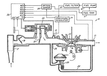
Referring to Figure 1, an internal combustion
engine system 10 includes a fuel tank 11 which supplies
fuel through a fuel pump 12 to the series connection o~
a fuel filter 13, a fuel press-lre reyulator 14 and a
fuel intake port 15 to be combined with air ~or
introduction into cylinder 16. The air ~low is throuyh
an air cleaner 17 past an air flow meter 18 and past a
throttle body 19 or an idle speed control air bypass
valve 20. Exhaust gas recirculation flow is from an
exhaust manifold 21 through a passage 22 to an exhaust
gas recirculation valve 23 and then through the intake
manifold 24 into the intake of the cylinder 16.
An optical sensor 25 monitors the index of
refraction of the fuel flowing from fuel tank ll to fuel
pump 12, fuel filter 13, pressure regulator 14, and fuel
intake port 15. In particular, the composition o~ the
return fuel from the pressure regulator 14 is measured
by the optical sensor 25 and returned to the fuel tank
11.
Optical sensor 25 produces a voltage
indicative o~ the amounts of two fuels in the fuel
mixture passing from fuel presure regulator 14 to ~uel
intake port 15. An optical sensor pick up structure for
sensing the index of refraction of a fuel mixture to
determine the proportion of two fuel types in the fluid
mixture is taught, for example, in U.S. Patent No.
4,438,749 issued to Schwippert on March 27, 1984.
An electronic engine control module 26
includes a microprocessor which interprets input data
from a number of sensors, and provides the prop~r
actuator r~sponse. Table l shows the control module
input sensor/switch nomenclature.
,, . :.
" .
:::: ;.
~ .
iL~ 7~ 3
TABLE 1
SENSOX/SWITCH NOMECLATURE
PIP Profile Ignation Pick~up
TP Throttle Angle Position
ECT Engine Coolant, Temperature
VAF Vane Air Flow Sensor (Inducted Engine
Air
A/C Air Condition Clutch (On or Off Switch)
N/D Neutral/Drive Switch
VAT Vane Air Tempe,rature
Based on information received from the sensors
listed in Table 1, the electronic control module 26
provides an output signal to the idla speed control air
bypass valve 20, fuel intake ports 15 and spark timing.
Control of engine operation by an electronic control
module is taught in U.S. 3,969,614 issued to Moyer et al
on July 13, 1976.
In operation, an electronic engine control
strategy of control module 26 is used to operate an
internal combustion engine. Ths control strategy is
divided into two portions: a base engine strategy and a
modulator strategy.
The base engine strategy provides the control
logic for a fully warmed engine during city and highway
driving. The base engine strategy is divided into the
following five exclusive engine operating modes, to
achieve optimum driving condition:
1. Crank mode
2. Underspeed mode
3. Closed throttle mode
4. Part throttle mode
5. Wide open throttle mode
~.- ,
:` , ~ ~; ' . !
,
` "`"~` '
`'~
.' . .
~ ' ,,
~7~ 3
The closed throttle, part throttle, and wide
open throttle mode are considered parts of the engine run
mode. A mode 6cheduler in the computer determines which
mode currently exists. The moclulator stra~egy modifies
the base engine strategy to correct for uncommon or
transient engine operating conclitions. These include
cold and excessively hot engine temperatures.
In accordance with an embodiment of this
invention, a flexible fuel strategy is part of the ba~e
engine strategy. This flexible fuel strategy calculate~
a desired air/fuel ratio of a f`uel mixture of ga601ine
and alcohol based on the percentage of alcohol, and
determines the correct spark timinq and fuel amount for
the various engine operating modes.
The flexible fuel strategy allows an internal
combustion engine to operate on any fuel mixture oP
alcohol and gasoline, such as methanol and gasoline, or
ethanol and gasoline. Since methanol and gasoline have
different combustion burn rate~, volumetric energy
content, vapor pressure, octane, and heat of
vaporization, the strategy changes engine operating
parameters, such as air bypa6s, fuel flow, and ignition
timing to provide op~imum engine operation. The two
fuels each have unique physical propertie6, such as
refractive index, that can be detected by a 6ensor. The
refractive index behaves in a predictable manner when the
two fuels are mixed. The fuel tank can be fully or
partially filled with, for example, methanol or gasoline
in any proportion. The desired air/fuel ratio may be
optimized for 6uch engine operating characteristics as
fuel economy and drivea~ility.
Optical sensor 25 provides an output signal,
which characterizes the index of refraction by a
frequency, to the electronic engine control module 26.
The flexible fuel strategy synchronizes the output from
~,
,, :,
~7~ 3
op~ical sensor 25 with an internal machine clock of the
engine control module 26 to generate a frequency
characterizing the optical sensor output signal. For
example, as shown in block 72 of Fig. 3~, the frequency
can be equal to one divided by the product of two times
the difference (DELMG) between the pre~ent machine time
of electronic engine control module 26 (i.e. the end of a
pulse), and the last machine interrupt time from the
optical sensor's output (i.e. the beginning of the
pulse). The frequency thus calculated characterizes the
percentage of methanol (PM) in the fuel mixture. The
following equation is used in the 60ftware calculation:
PM ~ FMS) x FN414) + (FMS x FPM)
wherein: PM = Percentage methanol
FN414 = Predetermined relationship between
the percentage of methanol and the
sensor frequency (see Fig. 4)
FPM = Predicted or known percen~age of
methanol
FMS is chosen to be a constant value of either o or 1 and
allows the percentage of methanol to be calculated by the
known percentage methanol value (FPM) or by a sen60r
value. When FMS equals 0, the percentage of methanol is
determined by the output signal of optical sensor 25.
When FMS equal6 1, the electronic engine control module
calculates the percentage of methanol based on the known
percentage methanol value (FPM).
The stoichiometric air fuel ratio (AFR1) i6 then
calculated based on percentage methanol. This
calculation is linearly interpolated between the
stoichiometric value Gf 6.4 for methanol and 14.6~ ~or
gasoline.
Where: AFRl = calculated air fuel ratio for stoichiometry
= (6.4 x PM) ~ (14.64 x (l-PM))
'- :
59
-- 8
The general flow diagram for the ~lexible fuel
st~ategy i8 shown in Fig, 2, ~lock 50 determines the
frequency output of optical sensor 25 in respon6e to the
composition fuel mixture, The logic flow then goes to
block 51 which determines the percentage of alcohol in
the fuel mixture as a function of frequency of the output
o~ optical sensor 25, Logic ~:Low conti~ue~ to block 52
which determine~ the air fuel ratio of the fuel mixture
for optimum engine operation. The flexible ~uel strategy
is stored in the background routine modules o~ the
control strategy. Tables 2 and 3 give the definition o~
all the variable names used in this strategy and shown in
Fig. 3A and Fig. 3~.
TABLE 2
15 NAME DEFINITION UNITS
AFRl Stoichiometric Air Fuel
Ratio
AO Fuel Injector Slope LBMF/Sec
ARCHG ~ir Charge Per Intake LBMA/Intake
Stroke
AVAMVL Average Vane Air Me~er LBS/Min
Value (Intake Air Flow)
BASEPW Injecto~s Base Pulsewidth Sec
CARCHG Cranking ~ir Charge Per LBMA/Intake
Intake Stroke
CR~NKING PW Injectors Cranking Sec
Pulsewidth
DELMG Time Del~a for Methanol/ Sec
Ga~oline Sensor Input
30 ECT Engine Coolant Temperature Degree6 F
EFIPW Final Injectors Pulfiewidth Sec
EM Enrichment Mul~iplier
. , : .
" ,
,
;1~7~ 3
FMS Forced Methanol Sen~or
Value
FP~ F'orced Peecentage of %
Methanol
5 KSl Spark Adder Degrees
N Engine Speed RPM
OFFSET Injector Pul6ewidth Sec
off~et
PM Percentage Methanol %
10 SAF Fi.nal Spark Advance Degrees
TFCHG Transient Fuel Sec/Inj
Pulsewidth
WOTEN Wide Open Throttle Fuel
Enrichment Multiplier
15 Y Normal Part Throttle
Spark Multiplier
TABLE 3
NAMæ DEFINITION
FN136 Cold Air Spark Adder Ba6ed on Inlet Temperature
FN137 Normalized Spark Multiplier Based on Percent~ge
Methanol
FN139 Wide Open Throttle Spark Adder Based on Engine
Speed
FN349 Cranking Fuel Enrichment Multiplier for Methanol
Based on ECT
FN350 Cranking Fuel Enrichment ~ultiplier for Ga~oline
Based on ECT
FN351 Volatility Interpolation Function Based on
Percentage Methanol
FN414 Mutliplier for Percentage of Methanol Ba~ed on
Sensor Frequency
FN900 Gasoline Fuel Enrichment Mul~iplier for a Cold
Eng:ine Based on ~CT Input
" ~
: ' ' ' ,.;' -
.
1~'7~:3~1L5~3
- 10 -
FN901 Lean Fuel Multiplier for Methanol as a Function
of Engine Speed and Load
FN905 Lean Fuel Multiplier for Gasoline as a Function
of Engine Speed and Load FN908 Fuel Enrichment Multiplier - as a Function of
ECT and Time Since Crank
FN910 MBT Base Spark Advance Table for Gasoline as a
Function of Engine Speed and Load
FN912 Cold Spark Advance ~dcler Table as a Function of
ECT and Load
FN913 EGR Spark Advance Adder Table Based on Engine
Speed and Load
FN919 MBT Base Spark Advance Table for Methanol as a
Function of Engine Speed and Load
F~9~9 Methanol Fuel Enrichment Multiplier ~or Cold
Engine Based on ECT Input
Fig6. 3A and 3B ~how the particular equations
and the logical sequence which are part of the flexible
fuel strategy. Blocks 70 through 88 are sequentially
lo~ically coupled to the next block in numerical order.
Block 89 is coupled back to block 70. Each of blocks 71
~hrough 88 also ha~ an output coupled back to block 70
which performs an overall management of the logic ~low.
CTVlA block 72 is used to convert sensor input
values to engineering units and correlates the methanol
sensor output with the percentage methanol. Fun~tion
FN414, shown in Fig. 4, show6 the correlation between the
sensor ~requency and the percentage methanol. Optimum
air fuel ratio is calculated based on the percentage of
methanol. This percentage is normalized to a value
between zero and one. The normalized value is used to
interpolate between the amount of ~uel necessary if the
mixture were entirely yasoline or entirely methanol.
. ,.~ ~ .
,~" ~
~7~3~;;'3
Fuel 1 block 79 i6 used to calculate the
cranking and base fuel pulsewidth of a signal used to
activate a fuel injector. The block calculates the
cranking fuel pulsewidth by using the value o~
stoichiometric air fuel ratio (AFR1), enrichment
multiplier (EM) and cranking air charge per intake stroke
(CARCHG) as shown in Fig. 3A. The enrichment multiplier
is temperature and fuel composition dependent where the
enrichment value decreases ~s ~FRl or engine temperature
increase6.
During the cranking mode of engine operation, a
desired air fuel ratio is establi6hed and a predetermined
function relates the amount of fuel needed as a function
of engine operating temperature. The amount of fuel
mixture i8 compensated to take into accoun~ the different
volatility of the fuel mixture constituents at different
engine operating temperatures. First, the amount of
methanol needed for a desired air fuel ratio at the
engine operating ~emperature is determined. Second, the
amount o~ gasoline needed Eor a desired air fuel ratio at
the engine operating temperature is determined. Then
there is an interpola~ion between the amount6 of gasoline
and methanol determined as a function of the percentage
of methanol in the actual fuel mixture.
The fuel injector pu.lsewidth equation for use in
the crank mode i~ shown in Fuel 1 block 79 of Fig. 3A.
The pul ewidth decrease6 in value as the stoichiometric
air fuel ratio increases. The cranking pulsewidth i~
determined by the equation:
Cranking PW = (CARCHG/(AFRl x 4 x AO)) x EM
The final pulsewidth for the cranking mode is:
EFIPW = Cranking PW
The fuel injector pulsewidth equation for use in the run
mode is shown in Fuel 3 block 80 of Fig. 3B. The
pulsewidth is based on the lean multiplier, AFRl, BASEP~,
- 12 -
and ARCHG value as shown in Figs. 3A and 3B. The lean
multiplier is obtained by interpolating between methanol
and gasoline fuel table6 for the desired equivalence
ratio. These tables indicate the amount of fuel
necessary for a desired air fuel ratio as a function of
engine speed and load. The lean multiplier is equal to
(l-PM) + FN901 + FN905 * PM, where PM is the percent
methanol and the functions FN 901 and FN905 take into
account differences in the flammability limits of fuel
mixture6 with various percentages o~ methanol. This
equation produces a linear interpolation between
functions defining desired air fuel ratio~ of the first
and second fuels (i.e. FN901 and FN905). The fuel
pulsewidth mofidier equation of block eo is equal to
FN908 * (FN900 * E'N351 + (1-FN351) * FN 929) * WOTEN *
LEAN MULTIPLIER. This equation produce6 a non-linear
interpolation between the cold fuel enrichment functions
(FNsoo and FN929) through the use of a non linear
function FN351. In particular, a6 defined in Table 3,
FN908 is a fuel enrichment multiplier a~ a function of
engine coolant temperature and time duration since last
engine cranking, FN900 i~ a gasoline fuel enrichment
multiplier for a cold engine based on engine coolant
temperature input, and FN929 i~ a methanol fuel
enrichment multiplier for cold engine based on engine
coolant temperature input. Fig. 6 i6 a graphical
description of the volatility interpolation factor as a
non linear function, FN~51, of the percentage methanol of
the fuel mixture.
During the run mode of engine operation, a
desired air fuel ratio is established and a predetermined
function relates the amount of fuel needed a6 a function
of engine speed, engine load and engine operating
temperature. The amount of fuel mixture is compensated
to take into account the different ~olatility and
'
~,
.. ."
~L~ 70~ 3
- 13 _
flammability limits of the fuel mixture constituents at
different engine operating temperatures. First, the
amount of gasoline needed for the desired air fuel ratio
at a particular engine speed and load is determined.
Second, the amount of methanol needed for the desired air
fuel ratio at a particular engine speed and load is
determined. Then there is an interpolation between the
amounts of gasoline and methanol determined as a function
of the percentage of methanol in the actual fuel
mixture. Functions FN901 and FN905 take into account the
difference in flammability limits.
The spark advance is calculated in block 86 by
interpolating between the de6ired spark advance for
methanol (FN919) and the desired spark advance for
gasoline (FN910) based on percentage methanol. Each
spark table shows desired spark advantage a~ a function
of engine speed and load. That i8, controlling the
amount of spark advance for such a fuel mixture includes
sensing a parameter related to the percentage of one of
the fuels in the fuel mixture, determining a base spark
advance, and adjusting ~he base spark advance as a
function of the percentage.
Refering to Fig. 5, function F~137 graphically
illustrates a non linear spark interpolating function for
compensating ~park timing as a function o~ percentage
methanol in the fuel mixeure. The spark interpolating
function has a sub~tantial change between 0% and 50% of
methanol in the fuel mixture and very little change
between 50~ an~ lOo~ of methanol in the fuel mixture. In
~o part, the spark interpolating function of FN137 takes
into account the non linear effects the burn rate and
octane of fuel mixtures having different percentages of
methanol. The non linear 6park interpolating function is
used in accordance with the equation illustrated in block
36 of Fig. 3B:
. ..
, ~ , .
:
)1S3
Spark Advance Factor (SAF) - (FN137 * FN919 = (1-FN137)
* FN910) ~ FN136 ~ FN913
+ FN139 + FN912 + KSl
As noted in Table 3, FN919 provide6 the desired spark
advance for methanol as a function of engine speed and
load.
During the crank mode, the spark advance i6
advantageously a fixed value such as for example, 10
before top dead center of piston and cylinder relative
positionR. During the run mod~e, the spark advance is
dependent upon predetermined factors which are functions
of the temperature o~ the air entering the engine, the
percentage of methanol in the fuel mixture, the engine
~peed, the engine load, and the engine coolant
temperature.
It may be advantaqeous to use fuel composition
sensor~ other than optical sensor6. For example, fuel
composition sensor6 may be based on the dielectric
constant of the fuel mixture. Alte~natively, by
monitoring the fuel quantity and type introduced into the
fuel mixture, the fuel mixture composition can be
calculated and the information supplied to the electronic
engine control module. Engine operation can also be
csntrolled using feedback engine control in combination
with such engine oper~ing parameter ~ensors a6 exhaust
gas oxygen sensors or combu6tion pressure sen60rs. That
is, determining the percentage of the first ~uel in the
fuel mixture can be deduced from characteristics of
engine operation in response to applied engine control
parameters.
Various modifications and variations will no
doubt occur to those skilled in the arts to which this
invention pertains. For example, the particular
processing of the signals from the fuel composition
..
. :..
,
:.,,. ;... `
31 ;~ 7~ 9
- 15 -
sensor may be varied from that disclosed herein. These
and all other variations which basically rely on the
teachingfi through which this disclosure haæ advanced the
art are properly conæidered within the scope of thiæ
invention.
,, ~
.
'