Note: Descriptions are shown in the official language in which they were submitted.
o~
-- 1 --
PROCESS FOR SEPARATING CO2 FROM ~ G~SEOUS MIXTURE
Field of the Invention
The invention relates to a low temperature process
for the separation of CO2 from a gaseous mixture contain-
ing CO2 and light hydrocarbons by a multistage distilla-
tion, wherein the gaseous mixture to be fractionated is
separated, in a first fractionating stage, into an over-
head fraction containing essentially all of the Cl and C2
hydrocarbons, as well as a portion of the CO2, and into a
bottoms fraction containing essen~ially C3~ hydrocarbons
and the largest portion of the CO2; whereupon the bottoms
fraction is subsequently separated into a substantially
pure CO2 fraction and a C3+ hydrocarbon fraction.
Description_Of The Prlor Art
In the distillation of light hydrocarbons, especial-
ly Cl to C~ hydrocarbons having a relatively high propor-
tion of CO2, problems are encountered involviDg the freez-:
ing out o~ -the CO2. Such problems can occur, in par-ticu-
lar, in the processing of CO2-rich natural gases, i.e.,
natural gases having a CO2 content of at least about 5%,
or in tertiary petroleum extraction processes wherein CO2
is injected under high pressure into deposits, i..e.,
undersround deposits, and in addition to tbe recovered
'. ~
. .~.
- ~,
, , ~
~LX~ 33
-- 2 --
petroleum, an accompanying gas is obtained which contains
light hydrocarbons and can include, for example, between 5
and 95% C02. This variation is caused by the C02 content
gradually rising during the course of tertiary oll extrac-
tion, starting from a relatively low level to a very highlevel whereas the quantity of the light hydrocarbons con-
tained in the gas remains essentially constant. While the
C2 is to be mainly separated as an undesired impurity in
C02-rich natural gases it is also, in the field oE terti-
ary petroleum extraction, a desired product stream whichis to be reused by reinjecting under high pressure in-to
the deposit.
~ known procedure for the separation of C02 from
light hydrocarbons provides for a separation of a Cl frac-
tion from the mixture, in a first fractionating stage,followed by a fractionation of the remaining C2+-C02 mix-
ture into C02 and into a C2~ fraction in a further frac-
tionating stage. However, a number of difficulties occurs
in this fractionation. While separating CH4 and C02 under
the conditions usually prevailing in demethanizing, solid
C2 deposits form in the fractionating column. During the
subsequent separation of the C02 and C2+ hydrocarbons, C02
forms an azeotropic mixture with ethane, the azeotrope
having a C02 : C2 ratio of about 2 : 1, so that effective
fractionatio~ of this mixture by distillatory methods is
impossible without taking additional measures. Such addi-
tional measures include, for example, the so-called Ryan-
~olmes process (Hydrocarbon Processing, May 1982, page
131), the introduction of additives which prevent deposi-
tion of solid C02, or are intended to break the C02-ethane
azeotrope .
.-: ,,
:
~ ~ 7~ ~ ~3
Since these modes of operation are relatively energy in-
tensive, a process requiring less energy has been proposed
in assignee's U.S. application S.N. 7~3,727, filed June
12, 1985 (German Patent Application P 34 22 158.1);
in this process, the first fractionating stage i~ not a
demethanizer, but rather effects separation oE essentially
all the Cl and C2 hydrocarbons. The bottoms of this first
fractionating stage yields, besides the predominant por-
tion of CO2 contained in the gaseous mixture, the C3+
hydrocarbons which are fractionated in a single-stage or,
especially in case of very hi~h CO2 contents in the ga~e-
ous mixture, a two-stage distillation, into CO2 and a C
hydrocarbon fraction.
Objects Of The Invention
Accordingly r the present invention is based on the
object to provide a novel system to effect the above-
described separation. A preferred object is to provide an
improved system of that disclosed in the aforementioned
U.S. application, and particularly, to still further re-
duce the energy requirements of the process.
This and other objects have been attained, in a pro-
cess aspect, by a process for separating CO2 from a gase-
ous mixture containing CO2 and light hydrocarbons by mul-
tistage distillation, wherein the gaseous mixture to be
fractionated is separated in a first fractionating stage
into an overhead fraction containing essentially all of
the Cl and C2 hydrocarbons, as well as a portion of the
CO2, and into a bottoms fraction containing essentially
all of the C3+ hydrocarbons and the largest portion of the
CO2, and the bottoms fraction is separated, in a second
.... :,., , ~.,.. ~,
:: . .
:-'; .,, ': ' ~.,
- ~ ,, , ~
~ 3
fractionating stage, into a C02 fraction and into a C3+
hydrocarbon fraction, the improvement comprising that the
second fractionating stage is operated under a higher
pressure than the Eirst fractionating stage, and at least
part of the bottoms heating of the first fractionating
stage is effected hy liquid withdrawn from the bottoms,
which liquid is heated while cooling the head of the
second fractionating stage and is then recycled into the
bottoms of the first fractionating stage. Stated in
another way, the process comprises distilling the gaseous
mixture in a first column into an overhead fraction COD-
taining preferably at least 80% of the Cl and C2 hydrocar-
bons and a minor part, preferably not more than about 50~
of the C02, and into a liquid bottoms fraction containing
preferably at least 80% of the C3+ hydrocarbon and the
remaining C02; pumping a part of the bottoms fraction to a
second column operated under a higher pressure than the
first column to form a C02 overhead fraction and a C
bottoms fraction; passing another part of the bottoms
fraction from the first column in indirect heat exchange
with the overhead of the second column to at least par
tially condense the C02 overhead fraction and to at least
partially vaporize said another part of the bottoms frac-
tion from the first column; and recycling resultant at
least partially vaporized bottoms fraction to the bottoms
of the first column to supply reboiler heat therein, said
higher pressure in the second column being at least suffi-
cient to provide a temperature of the overhead fraction
therein which is higher than the temperature of the bot-
toms fraction from the first colu~n.
Brief Description_of The ~rawings
Various other objects, features and attendant advan-
tages of the present invention will be more Eully app.re-
ciated as the same becomes better understood when consid-
, .
::
::
.. , , :::. . .,: : :
~:, .: ,: ::
., . ,
~l~7~ 33
- 5 -
ered in connection with the accompanying drawings, in
which like reference characters designate the same or
similar parts throughout the several views, and wherein:
Figure l is a schematic outline of a preferred
embodiment of the process of gas separation.
The thermal coupling between the bottoms of the
first and the head of the second fractionating stages is
believed to be an essQntial feature of the process of the
invention. By raising the pressure level in the second
fractionating stage, it is possible to elevate the column
temperature and especially the head temperature to such an
extent, e.g., to about 270 to 300K, preferably 285 to
295K, in the head, so thak the required head cooling can
be performed at least in part, e.g., about 10 to 100%,
preferably about 30 to 100%, by indirect heat exchange
with a liquid stream Prom the bottoms of the first
fractionating stage; thereby creating a ~imultaneous
heating and a partial vaporization of the bottoms fluid so
that the recycling of the heated bottoms liquid stream
into the bottoms of the first ~ractionating stage effects,
at least in part, the necsssary bottoms heating at that
stage. The temperature difference between khe bottoms o~
the first fractionating stage and the head of the second
fractionating stage is about 5 to 20 R. Consequently, the
need for an external supply of energy for heating the
bottoms of the first fractionating stage, as well as for
cooling the overhead of the second fractionating stage, is
either greatly reduced or entirely eliminated; instead, it
is merely necessary to pump the bottoms liguid to be fed
into the sPcond fractionating stage to the higher pressure
by means of a pump, which is possible without any large
energy expenditure.
The pressure difference between the two fractionating
stages depends essentially on both the pressure in the
first fra~tionating stage, usually ranging between about
20 to 50 bar, preferably between 30 and 45 bar, and also
- . ~ . . . .
--. . :,
. .
.. , . . ~ , : - -
~,: :.
~L2'76~ 3
on the specific gas composition, with CO2-concentrations
ranging from 10 to 9S~.
The pressure difference must become greater if the
C3+-concentration in the feedgas increases. In general,
the pressure difference between the two fractionating
stages is between about 10 and 25 bar, preEerably 13 to 20
bar.
In one embodiment of the :invention, the bottoms pro-
duct to be Eed into the second fractionating stage, after
having been pumped to the higher pressure, is heated e.g.,
about 5 to 15K, while cooling the head of the second
fractionating stage. This represents not only significant
contribution, e.g., about 5 to 35% toward the head cooling
requirements in this stage, but also a reduction in the
necessary heating of the bottom oE the second fractionat-
ing stage.
Care must be taken so that, in the second fraction-
ating stage involving the further distillatory separation
of the bottoms fraction of the first fractionating stage,
the critical pressure of either the mixture or, respec-
tively, of the overhead and the bottoms product, is not
exceeded. The critical pressure of CO2 is 73.8 bar and of
propane, 42.6 bar. While conducting the process of this
invention, the situation can requently arise, particu-
larly if the first fractionating stage is operated under a
relatively high pressure, e.g.~ about 40 to 45 bar, that
the pressure difference required or especially advanta-
geous for thermal coupling between the bottoms of the
first and the head of the second Eractionating stages,
i.e.~ about 10 to 25 bar, preferably 10 to 15 bar
necessitates such a theoretical high pressure in the
~: .,
.. .... ,. 1 . ,
: . . ., ~,
: : . :`:. ~ : ' .
: ` ~. :' :' .:
~ ~ 0 ~3
second fractionating stage, that the critical pressure of
the C3+ hydrocarbons is exceeded, i.e., the separation of
C2 - C3+ cannot be completely achieved. In such cases,
the second fractionating stage, in a further preferred
embodiment of the process, is subdivided into two succes-
sive distillations wherein, in the first distillation,
conducted at the higher pressure, e.g., about 50 to 65
bar, preferably 50 to 55 bar the largest portion of the
C2 is discharged in essentially pure form as the over-
head, whereas the bottoms produces a mixture o~ C3+ hydro-
carbons as well as a sufficient quantity of C02 so that
the distillation is still carried out under subcritical
pressure; whereupon this liquid stream obtained from the
bottoms is fractionated, after expansion to a lower pres-
sure, e.g., about 25 to 35 bar, in the second distillation
so as to form essentially pure C02 as the head product and
a C3+ hydrocarbon stream as the bottoms product. Expan-
sion of the stream takes place to a pressure level suffi-
ciently distant from the critical pressure of the C3+
fraction, and at which separation ~-an be readily per-
formed. During expansion, pressure differences of about
15-30 bar, especially about 20-25 bar, are typically
bridged. The portion of C02 obtained as the overhead from
the first distillation column amounts to about 70-98% of
the C02 present in the first distillation column.
It is, of course, also possi~le to leave the amount
of ~2 that is obtained in the bottoms of the first dis-
tillation, representing only a relatively low proportion,
e.g., about 2 to 10%, of the entire C02 present in the
gaseous mixture, particularly in the case of gaseous
mixtures having a high proportion of C0~, for example
higher than about 50% C02, in the C3+ fraction. Conse-
quently, the performing of the second distillation is
refrained from, if the C02 proportion in the C3+ fraction
does not interfere in the utili2ation of this fraction
and/or in cases where there is no requirement for a high
... ... . .
` . ~: ' ,;
. ~
3l~7~:183
-- 8 --
recovery of CO2.
In the second fractionating stage, wherein a separa-
tion takes place between the CO2 and C3+ fractions, the
relative volatilities of the two fractions to be separated
S become relatively small at the increased pressures uti-
lized, it may become necessary to use a large distillation
column, i.e., a column having a large diameter and great
height, and/or requiring a large reflux ratio in the
column.
This possible problem can be readily avoided by
feeding a C4+ hydrocarbon fraction lnto the second frac-
tionating stage, this fraction being supplied to the dis-
tillation column at a zone positioned above, e.g., 20 to
40 trays, the feed point of the bottoms fraction of the
first fractionating stage. The addition of this fraction
effectively represents an oil scrubbing stage superimposed
on the distillation, which substantially simplifies the
CO2-C3+ separation. This is due to the fact that the
solubility of C3 hydrocarbons in a C4+ hydrocarbon frac-
tion is much higher than the solubility of CO2 therein.There-fore, the relative volatility of CO2 versus C3 is
enhanced by addition of C4+ hydrocarbons. A -typical quan-
tity of the C4+ hydrocarbon fraction which is to b eadded
to the second fractionation stage is about 8% of the gas
fed to the second fractionation stage. In this connec-
tion, it is important that the C4+ fraction be ~ssentially
free of C3 and lighter hydrocarbons, since these would
contaminate the CO2 obtained in the column head, or would
have to be separated again, causing an additional expen-
- diture.
In another variation of this embodiment of the pro-
,,
, ,,
; .. :: ::
~L2~0~L~3
g
cess, the C4~ hydrocarbons which are returned to the
second fractionating stage can be separated from the bot-
toms fraction which is obtained in the second fractionat-
ing stage.
Particularly when the process of this invention is
conducted with the objective oE obtaining a CO2 product
stream under very high pressures, it is advantageous to
operate the second fractionating stage so that the CO2 is
condensed at the column head and discharged in the liquid
phase, since it can then be pumped to the desired high
pressure without a large expenditure of energy. This is
the case, for example, in tertiary oil recovery where CO2
is injected lnto the deposits under high pressures of up
to 200 bar.
The process of this invention is suitable for the
processing of CO2-rich gases, i.e., gases having a CO2
content of higher than 5%, particularly more than 25% CO2,
and is utilized with special preference in case of gases
having more than about 40~ or 50% CO2. In some instances,
the CO2 content can become very high, for example, up to
95% of the gaseous mixture. The process is also suitable
for the handling of gaseous mixtures having a varying CO2
proportion~ for example, where initially relatively low
C2 proportions later rise to high CO2 proportions.
The overhead of the first fractionating stage,
wherein the Cl and C2 hydrocarbons are separated from the
gaseous mixture, also contains a fraction, e.g., about 2
to 30% of the CO2 from the gaseous mixture. This is
because the portion of CO2 corresponding to the CO2
azeotrope with ethane will unavoidably be discharged over-
head, together with the C1-C2 fraction. The particular
proportion of CO2 is independent of the CO2 content of the
feed gas mixture, and instead depends solely on the C2
content of the gaseous mixture. Therefore, with a very
high CO2 content but a low C2 content of the gaseous mix-
:, ,
1~7~ 3
-- 10 --
ture, this 106s 0~ C2 i~ relatively small, wherein the
amount of C02 loss becomes larger in case of gases having
a relative minor C02 content and also a relatively high C2
content. In order to eliminate these losses and, particu-
larly, to be able to perform the process of this invention
under favorable conditions in case of relatively low CO2
contents, an additional embodiment of the invention pro-
vides that substantially the entire amount o~ C02 is sepa-
rated from the overhead fraction of the first fractionat-
ing stage and is reintroduced into the gaseous mixture to
be fractionated. Separation of the C02 from the overhead
of the first fractionating stage can take place in any
desired way known to those in the art, for example, by a
scrubbing step or by a membrane separating method. The
result of the separation is not only the obtaining o~ a
C02-free, Cl-C2 fraction, but also an CO2 enrichment, due
to the recycling of an amount o~ C02 corresponding to
about 2.5-times the quantity of C2 hydrocarbons, into the
gaseous mixture; this enrichment finally leads to such
high C02 concentrations, e.g., about 20 to 95%, that the
C2 contained in the crude gas can be removed at the
bottoms of the first fractionating sta~e.
It is advantageous to remove C02 at the bottom of
this ~irst separation step because this frackion to which
the whole feed gas is subjected can be operated at
temperatures at which C3 refrigerant can be used.
Additional details of the process according to the
present invention will be described below with reference
to an embodiment schematically illustrated in the figure.
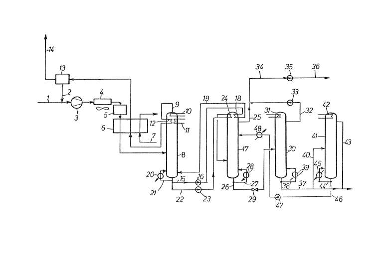
Example
Via conduit 1, desulfurized gas stream from a ter--
tiary petroleum recovery process is supplied, mixed with
substantially pure C02 recycled via conduit 2, and subse-
quently compressed in compressor 3 to a pressure of 40
... ~.. ,~, , ~
.
. . ..
:~ .
12t70~
bar. After cooling off the heat of compression in a cool-
er 4 to 312K, the gaseous stream passes through a drying
station 5 and is thereafter cooled in heat exchanger 6 to
a temperature of 270K by indirect heat exchange with
refrigerant conducted in conduit 7, and introduced into a
first distillation column 8. The gaseous mixture fed into
the distillation column 8 consists of 88.1% CO2 and also
contains 3.0g nitrogen, 5.2~ methane, 0.9% ethane, 0.6%
propane and 2.2~ C4~ hydrocarbons.
Column 8 operates under a pressure of 40 bar and at
a bottoms tempera-ture of 280K. ~uring this operation,
the entire methane and ethane content are obtained in the
column head, along with the nitrogen contained in -the
gaseous mixture, and a portion of the CO2. By way oE
conduit 9, an overhead product is withdrawn from the
column head which contains 35.9% CO2, 21.3% nitrogen~
37.1~ methane and 5.7% ethane. In order to maintain a
head temperature of 238K, the head of column 8 is cooled
by an indirect heat exchange with the coolant streams
conveyed through heat exchangers 10 and 11, as well as by
means of the overhead stream which is passed through heat
exchanger 12. After heating up in heat exchanger 12, the
overhead is further heated in heat e~changer 6 to about
305K against gaseous mixture to be cooled and is subse-
quently conducted into a separating unit 13, for example,by a scrubber or a membrane separating unit, wherein C~2
is separated from the overhead. The thus-separated CO~,
constituting about 4~ of the amount of CO2 contained in
the crude feed gas, is returned via conduit 2 into the
feed gaseous mixture supplied by conduit 1. The now
CO2-free gas from the separating unit 13 is withdrawn by
way of conduit 14 and passed on, for example, to a further
fractionating unit.
At 280K, a liquid stream is obtained in the bottoms
of column 8 which consists of 96.6% CO2 and further in-
:' ' . ~ :
: : . , :
: : ~.: :
- . .
~7~
-- 12 --
cludes 0.1% ethane, 0.7% propane and 2.6% C4+ hydrocar-
bons. ~ first, partial stream, of this liquid is conduct-
ed via conduit 15 and pump 16 to the head of a subsequent
column 17, in order to effect head cooling at that loca-
S tion by indirect heat exchange in heat exchanger 18. The
pump 16 is merely a conveyor pump which need no-t overcome
large, e.g., greater than about 5 bar, pressure diffe-
rences. After partial vaporization in head cooler 18, the
bottoms fluid is recycled to column 8 via conduit 19 and
fed into the bottoms at a temperature oE 289 K. The par-
tial stream of bottoms liquid withdrawn by way of conduit
15 accordingly effects, on the one hand, the largest por-
tion, e.g., about 60 to 80%, of head cooling for column 17
as well as, on the other hand, the largest portion of
bottoms heating for column 8. A bottoms heater 20
supplied by an external energy source is also provided in
the bottoms of column 8 and is utilized for regulating
purposes; if necessary, a partial stream 21 of the bottoms
liquid can be passed through this heater.
The portion of the bottoms liquid obtained in column
8 which is to be further fractionated is conducted via
conduit 22 to a pump 23 and pumped to a pressure of 55 bar
and temperature of 282.5K. The thereafter subcooled bot-
toms product is heated in heat exchanger 24 at the head of
the subsequent column 17 to 289K and then enters the
column 170
~istillation column 17 is operated under a pressure
of 55 bar and at a head temperature of 291K and a bottoms
temperature of 353K. In this column, the largest portion
of CO2 is separatedr in essentially pure content, from the
C3~ hydrocarbons and withdrawn in the liquid phase from
the column via conduit 25, contaminated merely by 0.1~
ethane. Since the column 17 is operat~d above the criti-
cal pressure of the C3+ hydrocarbons of the gaseous mix-
ture, i.e.p approximately 40 bar, it is impossible to
, - ,~. :
,
..
. .: : :~
.
~t~183
obtain this fraction in pure form as the bottoms liquid of
column 17. In order to remain an adequate distance from
the critical pressure, a CO2 proportion is permitted in
the bottoms, so that 38.0~ CO2 is present in the bottoms
liquid discharged via conduit 26, as well as 3.9~ propane
and 58.1% C4+ hydrocar~ons. A portion of this bottoms
11quid stream is branched off via conduit 27, heated in
heat exchanger 28 and returned into the column bottoms for
the bot-toms heating oE column 17. The residual portion is
expanded in valve 29 to a pressure of 30 bar and intro-
duced into column 30, which operates at a head temperature
of 267.5 K and a bottoms temperature of 452 K. In this
column, the residual CO2, constituting less than 2~ oE the
C2 contained in the original feed gaseous mixture, is
separated from the C3+ hydrocarbons. During this step, a
heat exchanger 31 is utilized for the head cooling of
column 30, a suitable refrigerant, for example, propane,
being conducted through this heat exchanger. The CO2
obtained in the liquid phase at the head of column 30 is
withdrawn via conduit 32 and pumped by means of pump 33 to
the pressure of the liquid CO2 discharged from column 17
via conduit 25, i.e., 55 bar, and is subsequently com-
bined with this liquid CO2 stream. The two combined
liquid CO2 streams then pass via conduit 34 to a pump 35
wherein they are pumped to a desired, high final pressure,
for example, about 100 to 200 bar, before exiting by way
of conduit 36.
A CO2-free C3+ fraction is obtained Erom the bottoms
of column 30 and is discharged via conduit 37. A portion,
e.g., about 60 to 70~, of the bottoms liquid branches off
via conduit 38, is heated in heat exchanger 39, and
returned at 460 K for heating the bottoms of column 30
into the bottoms of the latter. A portion of the C
product fraction withdrawn by way oE conduit 37 is
conduc-ted via conduit 40 to a further separating column
-. ' ' ~ ''` ~.` ': ., ' .' .- '
. ' ' ; ' . ~: ,
~27~ 3
41, i.e., a distillation column wherein a separation of
propane and the C4+ hydrocarbons is performed. This
column operates under a pressure of 18 bar, at a head
temperature of 318 K, and at a bottoms temperature of 425
K. For head cooling, a heat exchanger 42 is ukilized,
which is cooled by air. A li~lid propane stream is
obtained as the overhead of the column and is withdrawn
via conduit 43 and combined wi1:h the second partial stream
lo discharged by way of conduit 37. The C4+ hydrocarbons are
collected in the bottoms of column 41, a partial stream oP
these being withdrawn via conduit 44 and being recycled,
after heating to 430K in heat exchanger 45, ~or bottoms
heating into the column bottoms. The ramaining C4+
product stream is withdrawn via conduit 46, pumped in
pump 47 to the pressure of column 17, i.e., 55 bar, and,
after cooling in heat exchanger 48, to 302K, fed into an
upper zone, e.g., 20 to 40 trays above the feed point of
column 17. Even the feediny of a relatively small amount
of C4+ hydrocarbons into an upper zone oP column 17
substantially facilitate~ the separating action in this
column, which consequently enables a reduced structural
height and/or reduced diameter and/or reduced reflux
ratios in this column. It is, of course, not necessary to
separate the C4+ hydrocarbons to be fed into column 17
from the C3+ fraction removed via conduit 37. Any other
desired source of C4+ components can also be utilized for
this purpose. If the C3+ fraction in conduit 17 i5 to be
still further fractionated, e.g., into a propane fraction
and a C4+ fraction, or into a propane-butane fraction as
well as a C5~ fraction, it is, of course, also possible to
conduct the entire stream through column 41 and to recycle
just the partial stream of the thus-obtained heavy frac-
tion which is re~uired for utilization in column 17.
In the disclosed embodiment, a C02 content of 35.9%
~ was present in the overhead of the first fractionating
,
: , ' ,
- .
01~33
stage in column 8. This amount could be further reduced
in view of the fact that, based on the azeotrope formation
f C2 and ethane, there is always obtained a aertain
residual CO2 content in the overhead of column 8, for
example, about 20-25~. In the present example, this has
not been done since a greater amount of external refrig-
eration would be required for this purpos~ at the head of
column 8; in fact, changeover from a C3 refrigeratlon
cycle to a C2 re~rigeration cycle would be necessary in
such a case.
In a variation of the embodiment of the invention as
illustrated in the figure, the head of column 41 is not
cooled by air but rather by liquid withdrawn from a lower
part of column 17. The li~uid, after having been heated
or at least partially evaporated in heat exchanger 42, is
reintroduced into column 17, e.g., one tray below the tray
where it was removed from, thus resulting in an interme-
diate heatlng o~ the lower part of column 17 and, conse-
quently, reducing the energy demand for the sump reboi.ler
28. In a similar manner, a further intermediate heating
of column 17 may be effected by heat exchange of further
liquid withdrawn from a lower part of column 17 with crude
gas or other suitable process stream, e.g., in heat
exchanger 6. Furthermore, a~ the sump of column 38 is at
a higher temperature than the sump of column 41, the
liquid in line 40 may be used as heating medium in heat
exchanger 34, thus also reducing the heating energy
demand. In such case a further small trimmer heat
exchanger may be provided for further heating of the sump
of column 41, if still nec~ssary.
Upon further study of the specification and appended
claims, further objects and advantages of this ~nvention
will become apparent to those skilled in the art.
t~ d ~
.. . ..
' ` ~ ' '~ '" '. ,. `: ,:
.... .
'' , , : :''