Note: Descriptions are shown in the official language in which they were submitted.
~2~37~
01 This invention relates to apparatus used
02 to determine the thickness of meat and/or fat in a
03 carcass, and is usefully employed as a pork grader.
04 Farmers are paid for their meat carcasses,
05 often not only on the basis of total weight of the
06 carcasses, but also on the absolu~e or relative amount
07 o~ lean meat -to fat in the carcass. In order to
08 de-termine the absolute or relative thickness of lean
09 meat and fat, a probe is pushed into the carcass, the
probe carrying a light source and photosensor adjacent
11 its tip for sensing whether the probe is passing
12 through meat or at. The amount o~ light reflected
13 from the surrounding tissue from the light source, as
14 sensed by the photosensor determines whether the
sensor is embedded in lean meat or fat; fat reflects a
16 large amount of light while lean meat reflects a small
17 amount of light.
18 Such meat probes have been known and used
19 for many years, for example as described and claimed
in Canadian Patent 1,157,257 issued
21 November 22nd, 1983 to Hennessy et al and Canadian
22 Patent 1,075,457 issued April 15th, 1982 to Hennessy.
23 In both the aforenoted patents a probe
24 carrying a light and photosensor as described above
are pushed through the flesh of a carcass. As the
26 probe moves through the carcass the position of the
27 interfaces between highly and poorly reflective meat
28 are noted. A mechanical plate supported at the
29 surface of the carcass is linked to a position
measuring apparatus, i.e. a distance scale. The
31 distance that the probe moves between the aforenoted
32 interfaces provides the operator an indication of the
33 thickness of the meat and/or fat.
34 In Canadian Patent 1,075,457 a mechanical
scale is controlled by the movement of the probe
36 relative to the plate which rests on the surface oE
37 the carcass. The operator zeroes and notes the scale
38 - 1 -
r; ~r
~7~3~
01 values. However in this apparatus I have determined
02 that inaccuracies can occur due to operator error in
03 setting the scale and in reading the scale. The
04 mechanica] manner of linkage o~ the scale to the
05 moving parts also can introduce errors due to wear of
06 the apparatus.
07 In Canadian patent 1,157,257 signals
08 representing the maximum and minimum amounts of light
09 received by the light sensitive elements are stored in
a pair of capacitors. These reflectance values are
11 set when the probe is inserted into -the carcass. The
12 circuit automatically sets an intermediate level to
13 establish the interface signal level between lean and
14 fat meat. A second light source - light sensitive
element pair are located adjacènt a grid, which causes
16 the light sensitive element to pulse as the grid
17 passes between them when the meat probe is withdrawn.
18 By counting the number of pulses between the selected
19 intermediate voltage level and the ambient outside of
-the carcass, the depth of the outer fat level is
21 determined. In the latter patent it is only possible
22 to determine the outer fat thickness, and not the
23 thickness of the lean mea-t. Further, the maximum and
24 minimum signal values are stored on a pair of
capacitors, which can leak and thus can give rise to
26 erroneous readings. Further, the intermediate voltage
27 level is arbitrarily set, and due to the possible
28 interleaving of fat and lean meat, it is possible to
2g indicate an erroneous outer fat layer. In addition,
the aforenoted patent measures the thickness by a
31 direct physical determination by the position of the
32 probe. Because the signal levels stored are analog in
33 nature, they can drift, and can be rendered inaccurate.
34 The present invention, on the other hand,
can determine the thickness of both the meat and fat
36 layers (and/or their sum) with a high degree of
37 accuracy. Signals corresponding to the reflected
38 - 2 -
,~
~L~7~3377
01 light values are stored in a digital memory. Rather
02 than setting a val.ue arbitrarily between the highest
~3 and lowest reflectance values, I have determined that
04 a more accurate indication of the interface between
05 fat and lean meat can be obtained by operating on the
06 slope, tha~ is the rate of change of the reflected
07 light signal. The term reflectance value as used
08 herein is intended to mean the light signal level
09 received by the photosensor reflected by the carcass
from the light source.
ll ~ather than providing a mechanical
12 distance measuring apparatus as in the ~ennessy
13 patents, the present invention does not concern itself
14 with the absolute position of the probe or distance
measuring mechanical parts, and thus does not measure
16 the fat layer thickness directly from a base point as
17 the probe is withdrawn as in Hennessy. The presen-t
18 invention requires only that there should be relative
19 movement between the probe and an apparatus which
moves as the probe is inserted and withdrawn from the
21 carcass. This relative movement causes regular
22 readings to be taken of the reflectance values at
23 positions related to increments of movement, rather
24 than at absolute positions. Thus there is no need to
indicate a first signal reading position of'the probe
26 or mechanical distance measuring apparatus, with the
27 attendant mechanical linkage errors, as in the
28 aforenoted prior art patents.
2g Further, since all readings taken are
digitally stored, they can be moved to archival memory
31 for later recall in case of dispute between the farmer
32 and marketing organization, the total or accumulative
33 amounts of meat supplied by the farmer can be
34 established and kept by the present apparatus, and the
thickness values can be printed on a printer or
36 transmitted to a digital computer.
37 In general, the invention is a meat yrader
38 - 3 ~
~i,i
~7~37~7
01 comprising a probe for insertion through a meat
02 carcass to be graded, a light source, and a light
03 sensitive apparatus associated with the probe for
04 detecting light from the light source reflected from
05 the meat carcass as the probe is inserted and/or
06 retracted through the carcass, apparatus for
07 generating a first signal representative of the amount
08 of li.ght detected by the light sensitive apparatus,
09 apparatus for generating a second signal each
predetermined increment of axial movement of the probe
11 through the carcass, and apparatus for reading the
12 first signal each time the second signal is generated,
13 and for storing each read first signal. Further
14 apparatus determines the thickness of lean meat
represented by a stored low light reflection value or
16 the thickness of fat meat represented by a stored high
17 light reflection value comprising apparatus for
18 establishes the addresses of stored signals
19 representing the interfaces between low and high light
values, apparatus for determining the the number of
21 first signals stored between the addresses, and
22 apparatus for multiplying the number of first signals
23 stored between the addresses by a predetermined
24 constant to provide lean or fat meat thickness
representation signals for storage or display.
26 Another embodiment of the invention is a
27 meat grader comprising a probe for insertion through a
28 meat carcass to be graded, a light source, and a light
29 sensitive apparatus associated with the probe for
detecting light from the light source reflected from
31 the meat carcass as the probe is inserted or retracted
32 through the carcass, apparatus for generating a first
33 signal representative of the amount of light detected
34 by the light sensitive apparatus, apparatus for
generating a second signal each predetermined
36 increment of axial movement of the probe through the
37 _ 4 _
, ~ , . .
,.
01 carcass, apparatus for reading the first signal each
02 time the second signal is generated, and for storing
03 each read first signal in a memory at addresses
04 corresponding to the second signals~ and further
05 comprising apparatus for reading the stored first
06 signals, and for determining a high positive rate of
07 change in stored values at successive addresses, and
08 for establishing a first reference signal value at an
09 address location having a low signal level just prior
to the addresses having ~he high rate of change
11 values, determining a second reference signal value at
12 an address having a value related to a predetermined
13 minimum negative rate of change in the values with
14 increasing addresses, determining a third reference
signal value at the first address higher than that of
16 the second reference point following a range of
17 increasing values with increasing addresses, which
18 contains a value equivalent to that at the second
19 reference point, or a value a predetermined amount
less than the value equivalent to the second re~erence
21 point, whichever is the greater, apparatus for
22 subtracting the addresses of the first and second
23 reference points and multiplying the difference by a
24 constant to obtain a signal representative of fat
content of a carcass, and for subtracting the
26 addresses of the second and third reference points and
27 multiplying the difference by a constant to obtain a
28 signal representative of lean meat content of a
29 carcass, and apparatus for providing the
representative signals for display or storage.
31 Another embodiment of the invention is a
32 meat grader comprising a probe for insertion through a
33 meat carcass to be graded, a light source, and a light
34 sensitive apparatus associated with the probe for
detecting light from the light source reflected from
36 the meat carcass as the probe is inserted or retracted
37 - 4a -
38
~2~
01 through the carcass, apparatus for generating a first
02 signal representative of the amount of light detected
03 by the light sensi.tive apparatus, apparatus for
04 generating a second signal each predetermined
05 increment of axial movement of the probe through the
06 carcass, apparatus for reading the first signal each
07 time the second signal is generated, and for storing
08 each read Eirst signal in a memory at addresses
09 corresponding to the second signals, and further
comprising apparatus for reading the stored first
11 signals, and for determining a high positive rate of
12 change in stored values at successive addresses, and
13 for establishing a first reference signal value at an
14 address location having a low signal level just prior
to the addresses having the high rate of change
16 values, determining a first marker value "a" at an
17 address location higher than the first reference value
18 where the rate of change of stored values has
19 decreased by a predetermined amount over a
predetermined number of values having increasing
21 addresses, determining a second marker value "b" at an
22 address higher than the address of the first marker
23 value where the value is increasing or has remained
24 constant over a predetermined number of increasing
addresses, determining a third marker value "c" at the
26 address containing the largest value between the first
27 marker value and a value at an address a predetermined
28 number of addresses preceding, and establishing a
29 second reference signal value at the address midway
between the addresses containing the second and third
31 marker values, establishing a third reference signal
32 value at the first address higher than that of the
33 second marker value which contains a value equivalent
34 to that at the second reference point or a value a
predetermined amount less than the value equivalent to
36 the second reference point, whichever is the greater,
37 - 4b -
.. : .
.
~`'7~7~7
01 and apparatus for transmitting the first, second and
~2 third reference signals via a communication line to a
03 printer or a remote terminal.
04 ~nother embodiment of the invention is a
05 meat grader comprising a probe for insertion through a
06 meat carcass to be graded, a light source, and a light
07 sensitive apparatus associated with the probe for
08 detecting light from the light source reflected from
09 the meat carcass as the probe is inserted or retracted
through the carcass, apparatus for generating a first
11 signal representative of the amount of light detected
12 by the light sensitive apparatus, apparatus for
13 generating a second signal each predetermined
14 increment of axial movement of t~le probe through the
carcass, apparatus for reading the first signal each
16 time the second signal is generated, and for storing
17 each read first signal in a memory at addresses
18 corresponding to the second signals, and further
19 comprising apparatus for reading the stored first
signals, and for determining a high rate of change in
21 stored values at successive addresses, and for
22 establishing a first reference signal value at an
23 address location having a low signal level just prior
24 to the addresses having the high rate of change
values, determining a first marker value "a" at an
26 address location higher than the first reference value
27 where the rate of change of stored values has
28 decreased by a predetermined amount over a
29 predetermined number of values having increasing
addresses, determining a second marker value "bl' at an
31 address higher than the address of the first marker
32 value where the value is increasing or has remained
33 constant over a predetermined number of increaslng
34 addresses, determining a third marker value l'c" at an
address containing the largest value between the first
36 marker value and a value at an address a predetermined
37 - 4c -
1'~'7~3~
01 number of addresses preceding, and establishing a
02 second reference signal value at the address midway
03 between the addresses containing the second and third
04 marker values, establishing a third reference signal
05 value at the ~irst address ~igher than that of the
06 second marker value which contains a value equivalent
07 to that at the second reference point or a value a
08 predetermined amount less than a value equivalent to
09 the second reference signal value, whichever is the
greater, apparatus for subtracting the addresses of
11 the first and second reference signal values and
12 multiplying the difference by a constant to obtain a
13 signal representative of fat content of a carcass, and
14 for subtracting the addresses of the second and third
lS reference signal values and multiplying the difference
16 by a constant to obtain a signal representative of
17 lean meat content of a carcass, and apparatus for
18 providing the representative signals for display or
19 storage.
Another embodiment of the invention is a
21 meat grader comprising a probe for insertion through a
22 meat carcass to be graded, a light source, and a light
23 sensitive apparatus associated with the probe for
24 detecting light from the light source reflected from
the meat carcass as the probe is inserted or retracted
26 through the carcass, apparatus for generating a first
27 signal representative of the amount of light detected
28 by the light sensitive apparatus, apparatus for
29 generating a second signal each predetermined
increment of axial movement of the probe through the
31 carcass, apparatus for reading the first signal each
32 time the second signal is generated, and for storing
33 each read first signal in a memory at addresses
34 corresponding to the second signals, and
representative signals generated therein, and
36
37 - 4d -
,~
~,
. . .
.~ .
~L~71~
01 including a light emitting diode light source
02 connected to the input of a first analog to digital
03 converter, the Olltput of the converter being connected
04 to the data input of a digital memory, a photosensor
05 connected to the input of a second analog to digital
06 converter, the output of the second converter being
07 connected to the input of an address selector, the
08 output of the address selector being connected to the
09 address input of the memory, a microprocessor
connected to the address selector, the memory and the
11 analog to digital converters for enabling the
12 converters, and for controlling the address selector
13 and memory, whereby the ~irst signals are stored at
14 addresses represented by the second signals.
Another embodiment of the invention is a
16 method of grading a carcass comprising obtaining the
17 light reflectivity of the meat in a carcass at
18 progressive depths within the meat, storing digital
19 signals representative of the reflectivity at
successive memory addresses representative of a
21 relative location of the particular reflectivity from
22 an indeterminate position outside the meat to an
23 indeterminate depth within the meat, determining a
24 high rate of change in stored values at successive
addresses, and establishing a first reference signal
26 value at an address having a low signal level just
27 prior to the addresses having the high rate of change
28 values, determining a second reference signal value at
29 an address storing a value related to a predetermined
minimum negative rate of change in the values with
31 increasing addresses, determining a third reference
32 signal value at the first address higher than that of
33 the second reference signal value following a range o~
34 increasing values with increasing addresses, which
contains a value equivalent to that at the second
36 reference point, or a value a predetermined amount
37 - 4e -
77
01 less than the value equivalent to the second reference
Q2 point, whichever is the greater, and for subtracting
03 the addresses of the first and second reference point
04 and multiplying the difference by a constant to obtain
05 a signal representative of Eat content of a carcass,
06 and ~or subtracting the second and thlrd addresses and
07 multiplying the difference by a constant to obtain a
08 signal representative of lean meat content of a
09 carcass, and apparatus for providing the
representative signals for display or storage.
11 A better understanding of this invention
12 will be obtained by the detailed description below
13 with reference to the following drawings, in which: -
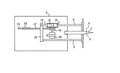
14 Figure 1 is a perspective view of a meat
probe,
16 Figures 2 and 3 are a side sectional view
17 and a top mechanical view illustrating details of the
18 invention,
19 Figure 4 is a block diagram of the
electronic portion of the invention, and
21 Figure 5 is a graph showing readings of
22 reflectance values which are stored in the memory of
23 the present invention.
24 Referring first to Figure 1, a pointed
probe 1 is fixed to and extends forwardly of a housing
26 2 to which a carrying handle 3 also is fixed. ~n
27 aiming plate 4 is fixed to the front of a pair of
28 shafts 5 which extend through apertures 6 in the front
29 wall of the housing 2. The probe 1 fixed to the
housing extends through an aperture 7 in the aiming
31 plate 4. ~ light source 8 and a photosensor 9 are
32 embedded within the probe close to the tip, and are
33 light-accessible at the surface thereof.
34 In operation, the probe tip is inserted
36 - 4~ -
.:.. ,.. 1: .;
~7~;~ ,7~
01 into the carcass and is pushed through the meat and
02 fa-t to the bone area. The aiming plate 4 rests at the
03 surEace of the carcass, causing shafts 5 to move
04 through the apertures 6 in the housing 2. According
05 to the prior art, the relative posi-tion o~ the aiming
06 plate 4 to the proba was directly measured, in
07 Canadian patent 1,075,457 for example by the use of a
08 mechanical gauge, and in Canadian patent 1,157,257 by
09 an elec-tronic counter which begins incrementing and
thus measuring the position at a predetermined signal
11 level inter~ediate the highest and lowest signal
12 levels detected on the photosensor. The thickness of
13 the meat was determined by a count of pulses stored in
14 the counter, each pulse being directly related to the
position of the aiming plate relative to the probe.
16 In the present invention determination of
17 the absolute position of the aiming plate relative to
18 the probe is avoided, in order to reduce or eliminate
19 the mechanical inaccuracy problems described earlier.
The position of the aiming plate in the present
21 invention merely causes readings of the signal value
22 received from the photosensor to be taken and stored.
23 Determination of the thickness of the lean meat and/or
24 fat is determined in a microprocessor, operating on
the stored signal values.
26 In the present invention a potentiometer
27 is rotated by movement of the aiming plate; a DC
28 current is applied to the potentiometer resulting in
29 an analog output signal to be generated across the
sliding tap and one terminal of the potentiometer in a
31 well known manner. This output signal is applied to
32 an analog-to-digital converter. The potentiometer's
33 rotation is calibrated so that preferably 0.55 ~m
34 movement of the aiming plate causes a 1 bit change in
the output signal from the analog-to-digital
36 converter. The use of the above will be explained
37 below, but first the mechanical structure to produce
38 - 5 -
:~,
'' ' ~. ~
. ~ .....
:
3'77
01 the above will be described with reference to Figures
02 2 and 3.
03 Figure 2 i:Llustrates a vertical section
04 thr~ugh the housing showing the aiming plate, a shaft
05 5 and the apparatus important to illust:rate the
06 principles of the mechanical structure. Aiming plate
07 4 is shown coupled to shaft 5 which ext:ends through
08 aperture 6 in the front wall of housing 2. A
09 potentiometer 10 has its rotational shaft axially
coupled to a pulley 11 and is mounted in an axis
11 orthogonal to the axis of shaft 5. A flexible strap
12 12 is fastened to the pulley at its end 13, the other
13 end 14 of the strap being fixed to a cross brace 15
14 which is fixed to and couples both shafts 5. Thus as
aiming plate 4 is pushed toward the housing 2, shafts
16 5 extend further into the housing, pulling strap 12,
17 and rotating pulley 11.
18 A bushing 16 extends axially from and is
19 fixed to the pulley 11, and a second strap or wire 17
which is fixed to an extension spring 18 is wound in
21 the opposite direction to strap 12 around bushing 16.
22 The other end of spring 18 is fixed at a fixing point
23 19 to the housing. Thus as the pulley rotates as the
24 aiming Plate 14 extends into the housing, spring 18 is
stretched, causing a counter restoring force against
26 the direction of movement of aiming plate 14.
27 Potentiometer 10 has its shaft coaxially fixed to
28 bushing 16 and pulley 11, and is itself fixed to the
29 housing 2. Thus as aiming plate 4 is pushed into the
housing, as pulley 11 rotates, the sha-ft of
31 potentiometer 10 rotates.
32 Turning now to Figure 4, a block schematic
33 circuit of the invention is illustrated.
34 Potentiometer 10 is shown as a block, but it wilL be
understood that a constant current is applied to it,
36 resulting in an output voltage dependent on the
37 position of the rotor or shaft of the potentiometer.
38 - 6 -
, ~
. ..
, . :
.
.~ . ' .
~7~37~7
01 Also a light source 8 (preferably a light emi-tting
02 diode) has a constant current source 20 connected to
03 cause it to illuminate in a well known manner. A
04 photosensor 9, preferably a phototransistor, receives
05 the light from light source 8 reflected from the
06 carcass, also in a well known manner.
07 The output o phototransistor 9 is
08 connected to an analog~to-digital converter 21, which
09 has its output connected to the data input of a memory
22. The output of potentiometer 10 is connected to
11 analog-to-digital converter 23 which has its output
12 connected to the input of an address selector 24. A
13 microprocessor 25 is connected to the
14 analog-to-digital converters 21 and 23, to address
selector 24 and to memory 22, in order to operate them
16 in accordance with the algorithm to be described
17 below.
18 Preferably a keyboard 26 and a display 27
19 are connected to microprocessor 25, the keyboard being
used for inputting data such as farmer number, carcass
21 unit number, etc. for storage in memory 22, and
22 display 27 being used for communication with the
23 operator, e.g. providing instantaneous readouts of the
24 light reflectance signal, meat thickness, or other
instructions, if desired, rather than merely storing
26 them for later display or recording in other
27 apparatus. ~icroprocessor 25 also has an input-output
28 port shown as lead I/0, for providing an output signal
29 of carcass number, and/or farmer number and lean
meant/fat thicknesses to a storage computer, to a
31 . printer, or other peripheral apparatus.
32 As indicated earlier, the potentiometer's
33 rotation is calibrated so that preferably O.S mm
34 movement of the aiming plate causes 1 bit change in
the output of analog to-digital converter 23. It has
36 been found that a 2000 ohm potentiometer is suitable,
37 - 7 -
., ~
., ~ .
7~377
01 and the analog-to-digital converter should have a
02 resolution selected -to achieve the above.
03 Microprocessor 25 monitors the output of
04 analog-to-digital converter 23 and each time there is
05 a 1 bit change in its output, due to rotation of the
06 potentiometer 10, it enables the address selector 24
07 to read the output of the analog-to-digital converter
08 23. The resulting address signal is then applied to
09 the input of memory 22, which is also a-t that time
enabled to read the output of analog-to-digital
11 converter 21 by microprocessor 25.
12 The analog output signal of photosensor 9
13 is applied to analog-to-digital converter 21, which
14 converts it to a digital signal. At the time of
addressing memory 22 the mi.croprocessor 25 also causes
16 the analog-to-digital converter 21 (or a latch at its
17 output) to output its signal as a data signal to the
18 data inputs of memory 22. Memory 22 thus stores the
19 digital signal level read at the address indicated by
address selector 24.
21 In the above manner a complete sequence of
22 readings will be obtained and stored in memory 22 as
23 the probe is inserted and/or retracted from the
24 carcass.
Figure 5 illustrates a continuous graph of
26 signal value stored at each me~ory location. The
27 graph consists of a series oE stepped amplitude
28 levels, each step corresponding to a specific
29 reading. Thus the axis "successive readings"
corresponds directly to memory locations, while the
31 signal value amplitude represents the digital value of
32 the stored signal at each memory location resulting
33 from the photosensor.
34 Looking from left to right, it may be seen
that a very low signal level, representing very low
36 reflectance (the probe being external to the carcass)
37 is first stored at low addresses, followed by high
38 - 8 -
, .
.
~L270~77
01 readings which represents the outer layer of fat.
02 Once the probe has entered a lean meat region, the
03 signal level drops to a low l.evel ex~ending over a
04 range indicated by L. The reflec-tance then increases
05 again as the pho-tosensor reaches the bone and sinew
06 region where there are additional regions of fat.
07 It is desired to determine various signal
08 level reference points in order to determine where the
09 meat and/or fat and/or ambient interfaces occur.
A first reference point (value and
11 address) determines the sensed ligh-t value when the
12 photosensor enters or leaves the carcass outer at
13 layer. This reference point "o" can be determined by
14 several possible means, the preferred one of which is
to determine the interface between the very low light
16 value and a high increase rate of change of light
17 (i.e. a high slope). Alternatively an absolute low
18 light value can be used.
19 In order to determine a second reference
point, first a point "a" is determined when the li~ht
21 value has decreased by a value o~ 60 or more units
22 over a distance of 3 mm from a peak following the
23 point "0". The microprocessor then searches for a
24 point "b" where the light value is increasing or has
been constant ~or three successive readings. This
26 point "b" is interpreted as the light value for the
27 lean meat (low reflection).
2s3 A point "c" is then determined which is
29 the largest light value between "a" and preferably six
readings prior to "a".
31 The second reference point (ref 2nd) is
32 established where the middle light value between
33 points "b" and "c" crosses the curve (which will often
34 be close to point "a"). This establishes the fat to
lean meat interface.
36 A third reference point is established
37 where the same light value as at the second reference
38 _ 9 _
~?.
..
~L27~ 7
01 point crosses the curve a second time, i.e. at "d".
02 If no point is found, the light value of the second
03 reference point is reduced by an arbi-trary value e.g.
04 10 is used. This sequence should continue until the
05 -third reference point is found.
06 Thus it may be seen that the light signal
07 levels between the first and second reference points
08 are due to the outer layer of fat, and the light
09 signal levels between the second and third reference
points are due to the lean meat. The light signal
11 levels between the first and third reference points
12 are caused by the combined thickness of fat and lean
13 meat.
14 Subtracting the addresses between the
reference points, and multiplying the differences by a
16 constant thus provides an indication of the fat, lean
17 meat and total thicknesses. These signals can be
18 stored in the memory for later retrieval, successive
19 totals can be added, the values can be output via the
I/0 port to a printer or computer, etc. It should be
21 understood that successive increasing memory addresses
22 is intended to mean increasing in either the positive
23 or negative direction.
24 The structure described above clearly has
significant advantages over the prior art both in
26 manipulation and storage of data, and in the accuracy
27 of thickness measurement, and also since a direct
2~ reading of thickness does not depend on a measurement
29 of absolute aiming plate position.
A person understanding this invention may
31 now conceive of alternative variations based on the
32 principles described herein. All are considered to be
33 within the sphere and scope of this invention as
34 defined in the claims appended hereto.
- 10 -
.,~