Note: Descriptions are shown in the official language in which they were submitted.
~76~3~9
~~~~ FIELD OF TEIE INVENTION
The present invention relates to methods of attaching a Iem~le
element, particul~rly female fastener elem~nts such as a nut, to a panel, wherein
the p~nel is pierced and the femPle element is installed in the pierced p~nel
opening in a continuous operation and an installation app~ratus.
The prior art includes ~elf-pier~ing nutsj which may also be
simultaneously clinched to secure the nut in the pierced panel opening, such as
disclosed in United States Patent~ Nos. 3,299,500 and 3,314,138, ~signed to the
assignee of the instant applicatiorl. The prior art Qlso inçludes a number of self-
riveting ~3uts, including nuts having an ann~ar ~irt or barrel portion wherein ~e
free end of the barrel portion is deformed radially outwardly in a die member to
form a mechanical interlock with the p~nel, see for example United States
Patents Nos. 3,~38,239 and 4,018,257. The 6elf-riveting nuts dis~losed in ~uch
patents ~re, however, sec~d to ~ panel having a prepierced panel ope~ing,
requiring two separate operations. Such methods ~lso require Yery precise
cer,tering of the nut relative to the prepierced penel opening, limiting the
irlSegrity of the instHllation, p~rticularly in produ~tion applications. United
:`' "' ~,.
152.353 ~ 3~
St~tes P~tent N~. 3,926,236, which is assigned to the assignee of the instant
application1 discloses ~ me~hod of attaching a nut wherein the panel is pierced by
a punch which extends through the nut bore to pierce and s~cure the nut in a
continuous oper~tion, however, the fastener is not a riveting type fastener having
a barrel portion extending through the pierced panel opening. Referen~e is also
made to United States Patent No. 3,800,401 which discloses ~ method of making
8 container closure such as a tag ring, in a continuous appllcation. It is
understood that the prior art ~lso includes various riveting techniques and
methods wherein the fastener element includes an annular end portion, which
may be press fitted through an opening in a panel, which is then ri~eted or
deforrned radially outwardly in a die member hhving an annular semi-toroidal die
cavity, which m~y include a projecting central die portion which receives the
annular riveting end o~ the lastener. The prior art also discloses rneens of
attaching stud-like fasteners, wherein the stud includes an annular end portion
which penetrates a plate or structural member, which may be deformed radia1ly
outwardly. Examples of such prior ~rt are cited in applicant's U.SO
Paterlt No. 4,555,838, issued December 3, 1985.
The method of attaching a female element or fastener of ths present
invention forms a unique and ;mproved assembly, particularly in relatively thin
psnels such ~s presently used in the automotive and appli~nce industries. The
methods of this invention are performed in a continuous operation and are
particularly suitabIe for application in 8 die apparatus or press having relatively
moveable press members, wherein the installation appar~tus is attached to the
die members within the press. The die press may be ut~ ed to simultaneously
form the panel into any desired configuration, making the method snd
instaLlation apparatus of this invention particularly suitable for m~Lss production
~pplic~tions. Several female elements or fasteners may be inst~lled with each
strolce of the die ~ress, eliminsting the req~rement for secondary operations
including prepiercing the panel.
-a-
152.353 ~ ~7~
SUMMARY OF THE INVENTION
As described, the method of this invention may be utilized to
permanently install a female element or fastener in a panel in a continuous
operation. The female element utilized in the method of this invention includes
a body portion, an ~mular barrel or skirt portion which extends from the body
portion having a free open end, and a bore which extends through the body
portion, preferqbly in co~cia~ alignment with ~he opening through the barrel
portion. The female element may be a nut having A threaded or unthreaded ~ore,
a bearing or similar element.
The method of this invention includes first locating the female element
~djacent a p~nel with the barrel portion free end facing the panel rleady for
installation; then, piercing a slug from the p,anel, forming a pierced panel opening
coaxially aligned with the body portion bore ~nd barrel portion opening. The
method then includes driving the barrel portion of the female element through
the pierced panel opening, prefer~bly drawing a tubular panel portion from the
plane of the panel, then deforming the barrel portion free end r~di~Ily outwardly.
Finally, the preferred method includes deforming the b~rrel portion free end
toward the body portion into a V-shaped annular chEmnel which opens toward the
body portion Qnd simultaneously driving the pane~ portion into the deYeloping U-
shaped barrel portion channel and deforming the panel portion in the channel to
form a secure mechanical interlock between the panel end the femsle or fastener
element.
In the method first disclosed in the ~bove identified U. s . pa~ent
4,555,838, the îemsle element Imnular b~rrel portion free end includes a
piercing surface adjHcent the opening to the annular barrel portion. The n ethod
includes piercing ~ ~lug from the panel with the barrel portion piercing surf~ce.
The panel slug is then disposed with the ~3ul~r b~rrel portion to prevent
co11ap6e of the b~rrel portion as the p~nel is deformed against the exterior
.
. '
152.353 ` ~7~3~
surface of the barrel portion ~nd formntion of the U~haped ~hannel portion at
the free end of the barrel portion. The panel 81Ug iS then removed from the
assembly by ~ punch received through the bore of the body portion.
The preferred method of inst~llation first disclosed in this ~pplication
includes piercing a slug from the panel with ~ punch disposed through the body
portion bore, which removes the slug from the assembly prior to driving the free
end of the female element b~rrel portion into $he panel. This method f~mplifies
the installation ~pparatus and provides other ~dv~nteges, as described below. In
either method, however, the female element may be attached to the panel in a
continuous operation &nd the panel is pierced prior to ~iving the female element
into the pierced panel opening ~nd forming ths preferred rrlechanical interlock
described
After the fastener element is locQted relative to the panel as described
ready for inst~llation, the barrel portion free end is prefer~bly biased against the
panel to preload the panel prior to piercing. This accurately locates the female
element relative to the p~nel and assures concentricity of the f}nal ~ssembly,
which is very important to the integrity of the mechanical interlock. Where the
p~nel is pierced with a punch disposed through the femele element body portion
bore, the internal diameter of the bore is prefer~bly less than the internal
diameter of the barrel portion ~pening. The punch ~en pierces a slug from the
panel having a diameter less than the internal diameter of the barrel portion~
providing additional p~nel in the mechanical interlock. The method then includes
driving the fem~e element b&rrel portion free end ~gainst the panel adjacent the
pierced opening, wherein the panel is preferably entrapped beneath the barrel
p~tion free end, drawing the panel from the plane of the mRin panel portion. As
des~ibed berein, the mecha~c~l interlock ~etween the panel portion adjQ~ent
the pierced panel opening and the female element is performed in a die member
or die ~tton. The preferred die button includes a ~mooth annul~r die cavity
which deforms the free er~d of the b~rrel portion radially outwardly, preferably
.. . .
.; .,
~7~ 3952.353
into the hvok or U~haped &nnular channel des~ribed and ~t e~ntr~l projecting
portion which is telescopcially received within the female element barrel portion
opening during the formatios~ of the mechanical interlock. The central projecting
portion also supports the p~nel portion adjacent the pierced panel edge during
piercing and the panel portion is drawn over the centr~l projecting portion of the
die by the free end of the barrel portion, thinning the p~nel portion as the panel
portion is driven into the ~nnular die c~vity.
In the most preferred method of this invention, the body portion of the
female element has an externAl dimension which is greater than the external
dimension of the barrel portion and the body portion includes an annular bottom
w~ll or surface which f~ces the panel. The bottom wsll of the body portion
preferably includes a plurality of projecting ribs which provide ~ntirotation
means for the female element and improve the ~ssembly as now described. The
preferred method then includes driving the ribs into the panel portion adjacent
the pi;erced panel edge, following receipt of the panel portion in the developing
U-sh~ped channel at the free end of the barrel portion, and then driYing the
bottom wall of the body portion into the panel portion which has been received in
the U~h6ped b~rrel portion, increasing the mechanic~l interlock.
The preferred embodiment of the inst~llation ~pparQtus disclosed herein
is p~rticularly adapted fcr perf~rming the newly disclosed method of install~tion,
wherein the p~nel is pierced by disposing a punch through the bore in the female
element body portion9 prior to driving the fem~le element into the panel, as
described. The ~pparatus includes a base member which is adapted to be fixed
relQtive to one die member of a die press having opposed rel~tively moveable eiie
members. An annular plunger ~s reciprocably supported in the base member
having ~ shank portion which extends through ~n opening in the base member.
The ~pparatus also includes a nose member which is normally spaeed from, but
moveahle toward the base member, having a plunger passage which telescopicaUy
receives the shank portion of the plunger. The Iwse member also includes
.
; ~
152.353 ~'70~
second p~ssage which intersects and f-ommunicates with the plunger passage for
receiving fem~le elements for instaUation by the apparatus. The annu~ar plunger
has an ~xial guide passage extending therethrough which telescopically receives a
piercing punch. The piercing punch has an axial length greater than the p]unger
and the piercing punch is fixed relative to the base member. In the disclosed
embodiment, one end of the piercing punch is att~ched to the die member to
which the b~se member is attached. The plunger is norm~y biased into the
plunger passage oi the nose member by a biasing or spring means, such that the
free ends of the plunger and piercing punch are generally ~igned adj~cent the
second passage in the nose member, such th~t a fastener element may be
received in the plunger passage ~nd aligned ready for install&tion opposite the
plunger and punch members. The installation app~rstus also includes ~n
actuating means which relatively closes the base and nose members upon receipt
of a femhle element aligned in the plunger passage ready for installation. In the
disclosed embodiment of the inst~llation appar~tus, the base end nose members
are relatively closed by closing the die press.
The disclosed embodiment of the install~tion ~pparatus performs the
method of this invention, ~s fo~lows. Relative closing movement of the nose and
base members extends the plunger ~nd piercing punch into the plunger p~ssage of
the nose member. The annular free end of the plunger first engages the opposed
end of the fastener element body portion, biasing the barrel portion free end
ag~inst a panel located opposite the plunger passage under the force of the
biasing me~ns. Thè piercing punch simultaneously extends into the bore of the
femele element body portion to eng~ge the pQnel. The punch then pierces ~ slug
fr~m the panel, which is driven out of the ~ssembly through the bore in the die
button, as described aboYe. ~inP~y, the femQle element is driven into the p~nel
by the p]unger and installed in the pierced panel opening, as described above.
--6--
152.3~3
In the preferred embodiment of the inst~ation llppar~tlas, the base
member includes a chamber and the plunger includes an enlarged head portion
which is reciprocably supported in the b~se membe* chamber. The biasing means
may then be loc~ted in the base member chamber, normally extending the
plunger shank portion into the nose member plunger passage. In the preferred
embodiment of the disclosed installation E~ppQrHtUS, the biasing means is
pneumatic pressure. The ~ppsratus includes a source of pneumatic pressure
which maintains a predetermined pressure in the base member chamber. The
pneumatic pressure escapes between the annular plunger and the piereing plmch
to the free ends of the plunger and punch members. Thi~ creates a vacuum
adjacent the second passage in the nose member, drawing e female e3ement from
the second passage tow~rd the pllmger and centering the female element in the
plunger pass~ge, ready for installation. As will be understood, the female
element must be flccurately aligned in the plunger passage for receipt of the
punch through the bore of the body portion. The vacuum created by the
pneumatic biasing means a~sures the ~lignment required.
Other advantages and meritorious features of the method of attaching a
female element to a panel and installation apparatus of this invention wlll be
more fully understood from the following description of the preferred
embodiments and the dl~wings, a brief description of which follows.
152.353
BRIEF DESCRIPTION OF THE DRAWINGS
.. . . _ _
Figure 1 is a partially crossffectioned t~ottom ~eva~ion of one
embodiment of a self-attaching femsle elemen~ or nut f~.s~ener which may be
utilized in the method of attachment and installation apparatus of this invention;
Figure 2 is a partislly cross~ectioned side ~.iew of one embodiment of
the installation apparstus of this invention inst~lling the nut fastener shown in
~igure 1 in ~ panel;
Figure 3 is a psrtially cross~ectioned side view of the insta~lation
apparatus shown in Figure 2 in the fin~l step of the installation;
Figure 4 is a partially cross~ectioned top elevation of a second
embodiment of a nut fastener which may be utilized in the method of installation
~nd inst~llation apparatus of this invention;
Figure 5 is a parti~lly cross~ectioned side view of a se~ond embodiment
of the installstion apparatus of this invention ready to install a nut fastener as
shown in ~igure 4;
Figure 6 is a pQrtislly cross~ectioned side view of the inst~lation
apparatus shown in ~igure S during an initial step in the method of installation of
this invention;
Flgure 7 is ~ partial enlarged side eross-section~l Yiew of the
installstion appal'AtUS QS shown in Figure 6;
Figure 8 is a psrti~l enl~rged side eross~ection~l view of the
inst~llation ~qpp~ratus shown in Pigures 5-7 illustrating a further step o~ the
method of installation of this invention;
'
1S2.353 ~L~7~)389
Figure 9 is a parti~lly cross-sectioned side view of the installation
apparatus shown in Figures 5 and 6 illustrating a further s~ep of the method of
installation of this invention;
~igure 10 is a partial enlarged ide cross~ectiona~ ~iew of the
installation appar~tus as shown in Figure 9;
Figure 11 is a partial enlarged side cross~eetis7nal view of the
installation apparatus shown in Figures 5-10 illustrating a further step in the
method of installation of this app~ratus;
Figure 12 is a partial enlarged side cross-sectional view of the
installation appsrat~ls shown in Figures 5-11 illustratin~ a further step in themethod of installation of this invention;
Figure 13 is a partial enlarged side cross-sectional view simil~r to
Figure 12 illustrating the final step of the method of installation of this
invention;
Figure 14 is a partial side cross~ectional view of the instsllation
apparatus shown in Figures 59 6 and 9 illustrating the position of the installation
apparRtus following installation of a nut fastener; and
Figure 15 is a partially schem~tic cross~ectional view of Figure 5 in
the direction oI view arrows 15-15.
-9-
152.353 ~27~9
DE _
rrhe following detailed description of the preferred embodimRnts
references Unlted States Patent No. 4,555,838, issued Dece~er 3, 1985.
Figures 1 to 3 of this application are taken from the above referenced
Patent and disclose the then preferred embodiment of the self-piercing an~
riveting nut fastener, installation apparatus and method of install~tion. This
application discloses an improved alternative method of att~ching a modified
self~iveting female element or nut fQstener and 8 detailed description of the
preferred embodiments of the instQllsUon apparatus 6nd method of this
invention. As used herein, ~emale element is intended to be generic to elements
having a threaded or unthreaded bore, which is preferably coQxislly aligned with
the opening in an integr~l ~nnul~r barrel portion, including self-riveting nuts,
rivets, bearing elements and the like. The disclosed embodiments are both nut
fasteners for ease of description.
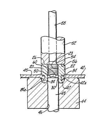
The self-piercing Emd riveting nut fastener 20 shown in Pigure 1 includes
a body portion 22 and an ~nnular barrel portion 24. The body portion 22 includes
~n annular driving surface 26 ~nd ~ bore 28 through the driving ~urface and
coa~ally aligned with the opening 30 through the barrel portion. The body
portion includes ~ bottom wall 32 adjacerlt the b6rrel portion a4 which includes ~
plurslity OI radi~lly projecting ribs 34. The snti-rotation ribs 34 are generally
triangular including a portion integral with the tubulsr barrel portlon 24. The
barrel portion 24 has a free end 36 which, m the disclosed embodiment, includes
relatively ~harp piercing surf~ce 38 Qt the opening 30 of the tubul~r b~rrel
portion and an arcuAte drawing surfQce 40.
As described more fully in the ~ve referenced~
Patent, the self-piercing and rive~ing fastener 20 is adapte~ to pierce the
p~nel and be perm~nently installed in the pierced panel opening. Figures 2 end 3
-10-
' ' ' , . ' '" '
:. ,
152.353 ~ 7t~39
disclose the working components of one embodiment of an inst~tion apparatus
~dapted to install the nut fastener shown in Figure 1. The nut f~stener 20 is first
locuted adjacent a panel 42 with the free end 36 of the b~rrel portion 24 facing
the panel. A die member or die button 44 is located on the opposite side of the
panel from the nut fastener. As shown, the die button 44 includes ~n armular or
semi-toroid&l die cavity 47 A jhoulder 45 surrounds the die cavity 47 whieh
supports the main portion of the panel 42. The disclosed embodiment of the die
button includes ~ bore 46 and a ce;lter die member 48 in fixed relation 3upported
in the ~ie button bore 46 during the installation of the nut fastener. As shown,
the center die member 48 includes a conical end portion 50 which projects from
the center of the ~nnular die cavity 47.
The self-pierring and riveting nut 20 i!s centered in an i~stallation
apparatus opposite the die cavity 47 with the nut bore 28 coAxially aligned with
the center die member 48. The installation apparatus includes a reciprocal
annular plunger 52 having Q center bore 54 and an annular end portion 56. In the
disclosed embodiment, a ram or punch 58 is located in the bore 59 of the plunger.
The annular end p~rtion 56 of the plunger 52 drives the free end 36 OI the nut
fastener 20 into the panel 42. As described more fully in the above referenced
Patent, the piercing surface 38 pierces a slug 60 fmm the panel
which is received and centered on the conical end portion 50 oS the center die
member 48. The free end 36 of the barrel portion 24 of the nut fastener is then
received against the semi-toroidal surface of the annular die e~vity 47 which
deforms the free end 36 of the barrel portion 24 radially outwardly into a hook-
shaped end portion or U-shaped annular channel 24aO The psnel psrtion 0~2R
adjacent the piel~ced panel opening is first deformed against the exterior sur~ace
o~ the annular barrel portion 24 as the b~rrel portion is leceived through $he
piesced p~el opening. The panel portion 42a is then de~ormed ~to the
developi~ U~haped b~rrel portion 24A by the ~nnular bottom wall 32 of the body
portion 22 and finally, the rib~ 34 are driven into the panel portion 42~ QS ~hown
in ~igure 2. As the annular wall 24 is driven into the a~mul~r die CQVity 47 the
152.353
slug 60 is moved upwardly into the opening 30 in the annul8r barrel portion 24
such that the slug 60 supports the tubul~r barrel portion 24 at the point of
greatest stress, preventing the annular barrel portion from collapsing inwardly
during the riveting step. Thus, the slug 60 perforrns an import~nt function in the
method of inst~ling the self~iercing and riveting nut fastener 20 shown in
Figures 2 and 3. Further, the resultar~t nut and panel assembly ~orms ~n
extremely rigid and secure mechanical interlock wherein the panel portion 42& is
locked in the U-shaped ch~nnel 24a îormed in the free end 36 of the nut f~stener
and the bottom w~ll 32 of the body portion 22. Further, the location of the
projecting ribs 34 in the annular bottom wall 32 does no~ weaken the assembly,
but serves to further deform the panel portion 42a, as shown.
Following installation, the slug 60 is ~iven out of the assembly by ram
or punch 58 RS shown in Pigure 3. As will be understood, the nut fastener is
installed in the panel in a continuous operation after the nut ~s located in the
instaIlation ~pparatus opposite the panel, as described. Further, as described,
the installation appsratus may be located in R di press, such EIS used by the
automotive industry to form p~nels. In such an application, ~e head assembly
including the reciprocal plunger 52 is att~ched to one die member or pl~ten and
the die button 44 is attached to the opposed die member. In a down~ierce
install~tion, the installation head is attached to the upper die shoe ~nd ~e die
button is attached to the lower die shoe~ It will be understood, however, that
the ~ssembly may be reversed in an l~pierce applicQtioll. The terms upper and
lower, top and bottom, are therefore relative terms and ~re used herein for
descriptive purposes only.
Figure 4 i~ustrates an impr~ved 6e~-riveting nut fa5tener 70 which iB
spec~ica~y Rdapted for insta~ation by the t~pe of apparatus disclosed in the
fo~owing figures. As wi~ be noted~ the se~-riveting nut 70 is of the same
gener~ configuration QS the nut fas~ener 20 described above. The nut f~stener
ineludes a body portion 7a ~nd ~n Qnnul~r or tubular b~rrel portion 74. The body
portion includes an ~nn~ar driving surface 76 ~nd ~ threaded bore 78 coaxi~lly
-12-
:~7~
L52.353
aligned and communicating with the opening 80 through the barrel portion. The
bottom wall or annular surface 82 of the body portion includes a plurality of
radial projecting ribs B4 ~d the free end 86 of the bEIrrel por~ion 74 includes a
chamfered surface 88 and an arcuate drawing surf~ce 90.
As will be understood from the detailed ~escription of the lnstallation
~pp~ratus ~nd method of installing the self-riveting nut fastener 70, the p~nel is
pierced and the panel slug is driven out of the assembly by a plmch received
through the nut b~re 78 prior to installing the nut in the pierced panel opening.
Thus, the p~nel slug is not received in the opening 80 of the tubul~ barrel
portion 74 to support the barrel portion during the riveting step. The barrel
portion 74 has thus been modified by providing a chamfer 88 adjaeent the opening
80 on the free end 86 of the barrel portion And the barrel portion has been
shortened to avoid collapse during the riveting step. An ~rcuate surface may
also be used in place of the chamfered surface 88.
The instaJlRtion apparatus disclosed in Fi~ure 5 and the remQining
~igures is adapted to be s~cured within a die press having opposed moveable
platens or die members. The female elements to be inst~lled in the panel are
received in a head assembly 100 having a base member 102 which may be
attached to the upper die member or ~ie shoe 104. As will be under~tood by
those skilled in the art, the head assembly is normally attached to Q backing
plate 106 which includes the fastening meHns for attaching the head assembly to
the upper die shoe. Normally, the head assembly 100 is attached to the backing
plate 106 and the backing plate is attached to the uppe~ die shoe 104 by bolts,
6crews ~r o~her convention~l fastening means. As s~t forth above, however, the
assembly Tnay be reversed in ~ pierce application, wherein the head a~sembly
100 i~ ~ttached to the lowel die shoe.
-13-
152.353 ~27~38~
The he~d ~ssembly 100 includes an annular plunger 108 having ~n
enlarged piston-like head portion 110 which reciprocates in ~ ch~mber 112 ~nd
the base member includes ~n opening 114 through which the plunger extends. In
the disclosed embodiment, the pllmger 108 is cy~indrical ~ the c~hamber 112 and
passage 114 are also cylindric~l to support the recipr~cal motion of the plunger.
It will be understood, however, that the cross-section~ configuration of the
plunger will depend upon the particular applic~tion The disclosed embodiment
of the self-riveting fastener 70 is also generally cylindri~-al, however, the shape
of the nut f~stener will ~lso depend upon the psr~iculQr spplication. For
ex~mple, the body portion 72 of the nut ~astener may be hexagon~ or ~t~gonal
~nd the shape of the b~rrel portion 74 may al~o be modified provided, however,
that the bore 78 of the female element body portion is preferably coa~ially
aligned with the opening 8û in the bArrel portion.
The head portion 110 of the plunger is sealed within the ch~mber 112 by
O-rings 116 and 118 on the plunger head portion 110 flnd at the end of the
chamber, respectively. An orienting pin 120 is provided in the disclosed
embodiment to prevent rotation of the plunger. The orienting pin includes a nat
surf~ce which slideably engages a flat surface on the plunger, preventing rotation
of the plunger rel~tive to the base member 102. A piercing punch 122 is disposedwithin the opening 123 which extends through the Rnnular plunger. In the
disclosed embodiment, the piercing punch includes Q head 124 which is attached
to the b~cking pl~te 106, opposite the head portion 110 of the plunger. The
piercing punch 122 is therefore fixed relative to the base membe~ 102 and the
plunger 108 may move relative to the base member 102 ~nd the piercing punch
122, within the chamber 112.
The head assembly lDO ~lso includes a nose member 126 whih mo~es
relati~e to the base member 102 during installation of the female element~ 70 as described hereinbelow. The nose member includes ~ plunger passage 1~8 which
receives the shank pol tion 130 o~ the plunger 108 ~nd the ~ncluded piercing punch
-14-
152.353 ~L~7~38~3
122. The nose member also includes a transverse ~eccnd ~s3age 132 which
communic~tes with the plunger passage ~or receipt o;f female elements, such ~s
the nut fasteners 70. In the disclosed ernbodiment, the nut f~steners 70 are
received through R plastic chute 134, which is attached to the nose member by Q
chute adapter 136. Access to the chute ~dapter is provided by a cover plate 138
which is attached to the chute adapter by screws or other fasten~ng means. The
nose member 126 i~ supported on the base member lU2 by a guide cylinder 139
which guides the movement of the nose member relative to the base member. A
stop pin 140 is provided which limits the space between the nose member and the
base member and the nose member is normally spaceù from the base member by
a spring me~ns, not shown. In the disclosed embodiment, a cavity 142 has been
provided in the upper die shoe which receives the end of the guide cylinder 139
when the nose member moves toward the base member and a spacer block 144 is
provided between the nose member 126 and the base member lOa to accurately
limit the relative movement. As will be understood the general construct;on of
the nose member 126 and base member 1029 including the cylinder guide 139,
stop pin 140 and the biasing spring assembly are known in the art Qnd are utilized
in pierce nut installation heads as disclosed in the patents assigned to the
assignee of the instant application, including United States Patents Nos.
3,098,576, 3,718,965 and 3,942,235.
A predetermined air preæure is maintained in the plunger chamber 112
by an air line 146, which is attached to the backing plate 106 by a fitting 148,~nd the backing plate includes an air passage 150 wh~ch provides communication
between the air line 146 ~nd the chamber 112. Ln a typical application, the line; ~ 146 is attached to the line pressure norm~ly available in a manuf~cturing plant,
which is generslly between ~0 snd 70 PSI. The pneumati~ pressure in the
chamber 112 provides ~ bi~sing mesns which nDrmally biases the plunger 108 into
the plunger pass~e 128 of the nose member 126. In this pasition, the free ends
of the plunger shank portion 130 and the piercing punch 122 are generally aligned
15-
. . .
,, ' :
52.353
adjacerlt the second pQssage 132 of the nose member, providing communication
between the second passage 132 And the pl~nger passage 12~, as shown in Figure
5. The nut fastener is norm~lly retained in the plunger passage, opposite the
plunger and piercing punch, in the ready position 70a, by spring biased fingers7not shown, as described in the above referenced patents.
A p~nel 160 is located opposite the installation head on the lower die
shoe 158. The installation die button 154 is located in the lower die shoe 158
coaxiAlly aligned with the plunger passage 128, the plunger 108 and piercing
punch 122. In the disclosed embodiment, the die button 154 includes a die button
insert 156 which projects from the eenter of the die button, as disclosed more
fully hereinbelow. Further, the panel is supported on convention~l spring biased
stripper pins 162 which ~ssist in the stripping of the nut and panel assembly from
the die button as will be understood by those skilled in the art. Further, in the
disclosed embodiment, the actuating means for the instsllation flpparatus
includes a conventional magnetic proximity switch located in the nose member
126, nor shown, which indicates whether a nut fastener is located in the ready
position 70a. The lead wire for the proximity switch is shown at 152. The
collventional magnetic proximity switch is normally located opposite the second
passage 132. When a nut f~stener is located in the ready position, 70a, the
proximity switch enables the actuation of the die press, wherein one of the die
members or shoes is moved toward the other die shoe, installing a nut fastener in
the panel. In 8 typical ~pplication, the upper die shoe 104 is moved tow~d the
lower die shoe 1$8, as now deseribed with the remaining ~igures.
Vpon downward movement of the upper die shoe 104, the nose member
12B first enga~es the panel 160, biasing the stripper pins 162 toward the die
button 154 and reducing the space between the nose member 126 and the base
member 102 es shown in Figure 6. This relatiwe mo~ement extends the ~lunger
sh~nk portion 130 into the plunger passage 128 to engage the annular driving
-16-
~ ~7~3`&~
152.353
surf~ce 76 of the body portion 72 of the nut fastener, moving the nut fastener
from the ready position to the pQnel, as best shown in ~igure 7. In this position,
the panel 160 is firmly clamped between the nose member 126 and the shoulder
17û of the die button 154 or the p~nel is clamped to the lower die shoe. The free
end 86 of the nut barrel portion 74 is biased against the panel by the shenk
portion 130 of the plunger member 10~, preloading the panel. As described
~bove, the plunger is resiliently biased into the plunger passage by the pneumatic
pressure in the base member chamber 112. As shown in Figure 6, the plunger
hesd portion 110 has not yet moved in the chamber 112, however the pressure of
the free end 86 of the nuS fastener ElgAinst the p~nel is su~ficient to slightly
indent or mark the panel, which is important to accurately coaxially align the nut
barrel portion 74 with the annular die cavity 172 in the die button 154 Md
maint~in the concentricity of the nut and panel assembly during the install~tion
of the nut fastener.
As best shown in Figure 7, the die button 154 includes a semi-toroidal
die cavity 172 ~d the die button insert 156 includes d projecting end portion 174
which smoothly continues the annular concave surf~ce of the die cavity. A
stepped bore 178 extends through the die button insert, which is coaxi~lly
~ligned with the piercing punch 122. Ln the disclosed embodiment, the die button
insert 156 is press fitted into the bore lS0 in the die button 154 and the die insert
includes sn enl~rged end portion 182 which accur~tely locates the insert in the
die button. As will be w~derstood by those skilled in the ~rt from the following
description of the method of inst~llation, the projecting end 17D, of the die button
insert is subje~t to wear and there~ore a separate replAceable insert h~s been
used. Il ~.Yill be ~derstood, however, that the die button may be ~n integr~l unit
as disclosed in the ~.~ve re~erenced .patent.
:
-17
" I'
. " . ~ .
~; ''
. . .
152.353
~L~7~3~8~
In the relati~re positions of the base and nose members 102 And 126
shown in ~igure 6, the piercing punch 122 is extended through the nut bore 7~ of
the body portion 72 and the opening 80 through the barrel portion 74 to eng~ge
the panel hS shown in Figure 7. As set forth above, the free end ~6 of the b~rrel
portion 74 is biased Qgainst the panel by the plunger shank portivn 130,
preloading the panel anà maintaining the coaxial ali~nment of the tubular b~rrel
portion 74 with the annular die cavity 172. Continued closing of the die press
moves the nose member 126 toward the base member 102 bec~use the nose
member is bottomed on the lower die shoe 158, QS sllown in ~igure 6. The
piercir~ punch 122 therefore moves relative ~o the plunger 108, through the
opening 123 in the plunger, biasing the panel into the annular die cavity 172 in
the die button and against the projecting end portion 174 of the die button inse rt
lS6, as sh~wn in Figure û. As will be noted, the free end 86 of the nut fastener
barrel portion 74 maintains the preload condition egainst the panel, as described
above. The panel 160 remains clamped between the shoulder 170 of the die
button 154 and the nose member 126.
C~ntinued relative closing of the die press causes the piercing punch
122 to extend through the panel and pierce a slug 184 from the psnel as best
shown in Figure 10. In this position, ~s shown in Figure 9, the head portion 110 of
the plunger head portion 110 remains slightly spaced from the backing plate 106,
such that the plunger is not yet fixed relative to the base membe~ 102, however,
the free end 86 of the barrel portion 74 remains preloaded against the panel
under the pneumatic pressure in the plunger chamber 112. The panel is pierced
between the chamf~red opening to the bore 178 in the die button insert 156 and
the outer edge of the pier~ing punch 122 and the p~nel slug 184 is immediately
removed from the assembly into the bore 17~ of the die button insert.
-18-
. ~
152.353
YYhen the plunger head 110 bottoms against the backing plate 106, $he
shank portion 130 of the plunger drives the free end 86 of the barrel portion 74
into the panel portion 160a adjacent the pierced panel opening as shown in Figure
11. The panel portion 160a is initiaUy entrapped beneath the free end ~6 of the
barrel portion and the convex suface of the projecting end portion 174 of the die
button insert, slightly thinning the p~nel portion and drawing ~he panel portion
into the annular die cavity 172. As the plunger oontinues to drive the nut
fastener into the die cavity :172, the free end 86 of the barrel portion 74 engages
the bottom semi-toroidal surface of the die cavity 172, deforming the barrel
p~rtion free end radi~lly outwardly ~s shown in Figure 12 at 86a. The psnel
portion adjacent the pierced panel opening is simultaneously drE~wn against the
exterior surface of the barrel portion 74 into a tubuI~r configurstion 160b, as
shown in Figure 12. Finally, the free end of the annular barrel portion is turned
tow~rd the body portion 72 of the nut fastener against the surface of the die
cavity 172 into a U-shaped channel 86b, whieh is hook-shsped in cross section as
shown in Figure 13. The annular surface of the female element bottom w~l 82 is
simultaneously driven into the panel, deforming the panel portion in the
developing U-shaped channel 86b ~nd enlarging the end of the panel portion, as
shown at 160c in Figure 13. Further, the pro;ecting ribs 8~ on the bottom wall 82
of the body portion are driven into the panel portion 16Dc, pro,riding sntirotation
means for the nut fastener in the panel and ~urther deforming the panel portion
in the hook-shaped end portion 86b of the barrel portion. The nose member 126
is now ~ully seated egainst the base member 102 ~s shown in ~igure 14. That is,
the base mernber 102 has bottomed against the E;pacer block 144, limiting the
rel~tive movement between the nose member 126 and the base membe~ 102.
~urther, the guide cylinder 139 has moved into the cavity 142 in t:he upper die
shoe 104.
--19-
"' ,~
1S2.353 ~7~3~
The assembly between the female element 70 and the panel 160 is now
complete. Upon opening of the die press, the base member 1~2 is first lifted
with the upper die shoe 104 until the nose member 126 is fully spaced from the
base member as shown in ~igure 5. As described above, the bgse u~d nose
members are normally spaced by a ~pring or other biasing me~ns. In the
disclosed embodiment, a s~iral spring is located in ~hle guide cylinder 139 biased
agQinst the upper die shoe 104. The nose member 1:26 is then lifted off of the
assembly and the stripper pills 162 lift the panel ~rom the shoulder 170 of the die
button. The feed mechan~sm, not shown, then feeds a fastener element from the
second passage 132 in the nose member 126 to the plunger passage 12~ to the
ready p~;ition 70a shown in Pigure 5. Værious feed and chuck systems are
disclosed in the flbove referenced pstents. A gr~vity feed may also be utilized,
particularly in the disclosed installation apparatus which includes a vacuum
assist, as now described.
As shown in Figure 5 and lS, a VQCUUm is created adjacent the second
nut passage 132 which draws a female element 70 adjacent the plunger passage
into the plunger passage 12~ and ~enters the female element relative to the
piercing punch 122 and plunger 1û8. The pneumatic pressure in the chamber 112
supplied by air line 146 escapes between the piercing punch 122 and the plunger
108 through the opening 123 through the plunger. Because the space between the
piercing punch 122 and the plunger 108 is substantially less than t~e volume of
the chamber 112, the velocity OI the air increases. When a female element is not
located in the plunger passage 128, the ~ir escapes through the plunger passage
128, creating a v~cu~n ~dj~cent the second p~ ge 132. This reduced pressure
tends to dr~w a f~stener 70 ~rom the second pQssage into the plunger passQge as
~hown in ~lgure 15, whioh is a compound cross~ectional view used to illustrete
the pressure diff erenti~l ~cting on ~ nut in the second pnssage, In actual
oper~tion, a small nut fQst~ner 70 will be drewn into the plunger passage 1~8 by
the vacuum described. More importantly, the ~Qcuum serves to oenter a nut
--20-
1:)2.353 ~IIL2~7~3~
fastener of the type disclosed beneath the plunger and piercir~ punch, assuring
orient~tion of ~ femRle element in the plunger passage, ready ~or installation.
This feature of the installation a~pQr~tus oî this invention is particulEIrly useful
in A gr~vity feed system.
Having described the preferred embodiments of the female element and
the install~tion appar~tus, it is DOW possible to summ~rize the preferred methods
of installation. As described above, the preferred method of instaUation includes
first locating a fem~le element ~djacent e panel with the free end of the b~rrel
portion facing the panel. In the method of attachment shown in Figures 1 to 3,
the free end 36 of the b~rrel po~tion 24 includes a piercing surface 38 which
pierces a slug 60 from the panel, forming ~ pierced panel opening which is
coaxi~lly ~ligned with the body portion bore 28 and the opening 30 through the
barrel portion. With the embodiment of the female element 70 shown in Figure
4, the p~nel is pierced by a piercing punch 122 which is disposed through the body
portion bore 78 and the opening 80 through the b~rrel portion 74. Next, the
female element barrel portion is driven through the pierced panel opening. In
Figures 1 to 3, the plunger 52 drives the free end 36 of the b~rrel pDrtion 24 ints
the panel to first pierce the panel 4a and then the free end 36 of ~e barrel
. .
portion is ~iven through the piereed panel opening to deform the barrel portion
free end radiQlly outwardly. The p~nel portion 42a B simultaneously deformed
~gainst the exterior surface of the b0rrel portion 24 into a tubular csnfigur~tion,
drawing the panel portion from the plane o~ the penel 42.
In the install~tion method di~closed in Figures S to 14, the plunger shank
portion 130 first bisses the free end 86 of 'che b~rrel portion 74 against the panel
160, preloading ~e p~nel as shown in Figure 7. The ~enter pwlch 122 then
deforms the p~nel into the die C~Yity 172 to eng~ge the projecting end 174 of the
die Insert 156 while the p~el rem&ins preloaded by the free end B6 of the barrel
portion, ~s shown in ~igure 8. The panel is then pierced by the center punch 122
and the p~nel slug 184 is removed ~rom the assembly, prio~ to driving the free
end 86 of the b~rrel poltion ~lltO the panel, as ~hown in ~igure 15. The ~ee end
-2~-
.
::
.......... ..
152.353 ~7~
86 of the barrel portion ~ then driven into the panel, entrapping the panel
portion 160a bene~th the free end of the barrel portion ar,d slightly ~hfnning the
panel portion, as shown ill Figure 11. The free end of the barrel portion is then
driven through the pierced pQnel opening ~nd ~gainst the ConCQve ~nnular w~ll of
the die cQVity 172, deforming the free end of tlle barrel portion radially
outwQrdly ss shown at 8Ba in Figure 12. As notecl above, the pQnel portion
adjacent the pierced panel opening is simult~neously drawn into a tubular
configuration 160b against the exterior surfa~e of the barrel portion 74.
Fir~lly~ in the most preferred method of this invention, the free end of
the barrel portion is deformed into a tJ~shaped ~nnular channel which opens
toward the body portion and the panel portion adjacent the pierced panel opening
is simultQneously deformed in the developing U~haped bQrrel portion to form a
secure mechanical interlock between the panel and the fem~le element. As
described ~bove in regQrd to Figures 1 to 3, the free end 36 of the barrel portion
24 of the female element is deformed ag~inst the concave annular w~ll of the die
cavity 47 into a U-shaped channel 24a and the panel portion 42a is deformed
within the hook-shaped portion, forming a secure mechQnicQl interlock.
Following formation of the nut and panel assembly, t~e slug 60 is driYen out of
the assembly, ~s shown in Figure 3. In the method of instsllation shown in
Figure 13, the free end 86b of the barrel portion is similarly deformed into a U-
shaped chRnnel portion and the panel portion 160c is deformed within tlhe bnrrel
portion channel, securely retaining the panel portion, as described above.
Having described the preferred embodiments of the method of att~ching
a female element to a panel and the preferred embodiments of the install~tion
~ratus of this invention, it will be understood that v~rious modifications may
be m~de to the method and the inst~llation apparatus within the purview o~ ffle
appended cilaims The oonfigur~qtion ~nd dimensions of the self-riveting ~emale
fastener, for ex~mple, will depend upon the p~rticular Qpplic~tion ~nd the panel
. .
-22-
.
,:
. ~, ... ".
~ ;~71[~3~
152.353
thickness. As described nbove, the disclosed femsle elements and methods of
attachment of this invention are pE~ticularly adRpted for permanent attachment
of the female e]ement to relatively thin panels, such as utilized for structural
components in the automotive and appliance industries. For example, the fem01e
element may be att~ched to relatively thin pAnels h~ving a thickness of
approximately 0.025 inches to relatively thick panels for the ~utomotive
industry having a thickness of 0.125 inches. The dimensions of the femRle
element will, of course, depend upon the thickness of the panel and the particular
application. A female element, such ~s a self-riveting nut, may be formeà of
medium carbon steels. Further, the configuration of the body portion of the
female element will depend upon the preferred application. Thus, the body
portion may be of Qny suitable configuration and the barrel portion may be
cylindrical, hexagonal, etc. The female elements may be formed by conventionsl
hot or cold forming methods.
,~
: .
~ ~3'
... . . .
` ~ , . . .
. : :
. ~ . :. ~
.;.