Note: Descriptions are shown in the official language in which they were submitted.
The present inventlon relates generally to the
application of cable ties to wire bundles or the like and
specifically to a tool that automatically dispenses. conveys and
applies discrete cable ties to wire bundles or the like, where
the cable ties are provided on a continuous ribbon.
Prior automatic cable tie installation tools have
utilized a cartridge to contain a number of discrete cable ties
and provide the cable ties sequentially to a dispenser mechanism
in the tool. Ths use of a cartridge to feed discrete cable ties
to an automatic cable tle installation tool presents inherent
limitations and operational difficulties that limit the
efficiency of the tool.
Any tool utilizing a cartridge has the inherent
limitation of only being able to apply as many cable ties as the
cartridge is designed `to hold. Application by the tool of all
the ties in the cartridge necessitates the exchange of the empty
cartridge for a loaded cartridge or the manual refilling of the
empty cartridge. Practical design constraints dictated by the
dimensions of the cable ties and the need ~or a portabla and
easily operable automa~lc tool have limited the number o~ cab:Le
ties carrled ln an lndividual cartrldge to approxlmately one
hundred cable ties.
Prior tools also require the cable tles to be loaded
into each cartridge in a specific and consistent orientation,
requiring careful and time consuming manipulation of individual
cable ties during the cartridge loading operation.
Compounding the above described ine~fi~lencies is the
fact that cartridge supplied tools lnherently have complex
mechanlsms to allow the detachable mounting of a cartridge
,7
" "' "', `
.~ ~
7~ )
and to sequentially dispense cable ties from the cartridge.
Such mechanisms must meet close tolerances in manufacture
and fit and must ~e carefully operated and maintained in
order to provide error free operationO Due to these con
straints, prior tool~ have failed to operate flawlessly
during the attachment of new cartridges. The tools often
will jam during the loading of a cartridge requiring the
waste of operator time to unjam and properly reload the
tool.
~0 All of the above problems contribute to a loss of over-
all efficiency in the prior automatic cable tie i~stallation
tools; a significant portion of an operator's time being
devoted to the loading of cartridges instead of to the
application of cable ties.
Additional problems inherent in supplying cable ties by
cartridge include the increased costs due to manufacture,
~torage and disposal of the cartridge.
Another problem of prior art tools i~ th~ use of
mechanical or pneumatic logic to control the many sequential
operational step~ necessary to dispense, convey an~ supply a
cable tie. The use o~ mechanical and pneumatic sy~t~ms to
contxol the various actions of a tool requires the use of a
large number of interacting valve~, linkages, etcO with the
concomitant expense of manu~acture and expense of main--
tenance that a tool having a large number of interacting
mechnical components entails9
Additionally, pneumatic logic systems are inherently
~ensitive to variance in pressure of their control 1uid or
to contamination of their control fluid, eithex of which can
cause timing erroxs ~n the control ~ystem. Due to the high
speed at which automatic cable tie in~tallation tools com~
plete a cycle, ~mall errors in control logic timing can
result in ~he ~ailure of the control logic to actuate the
mechanisms o~ the tool in proper operational order with the
attendant failure of the tool.
7~3 7~ ~
Prior autnmatic cable tie installation toola have
pneumatically conveyed the ties provided by the cartridge
through a tube at high ~elocity to a remote hand tool where
the tie is positioned around a bundle of wire and installed.
. Successful receipt of the tie by the remote tool requires
the tie to be brought to rest at the correct position within
the r~mote hand tool, relative to the other working mechan- ~
isms of the hand tool. Typically, a head stop or abutment
has been provided to stop and correctly p~sition the tie.
~he head stop being positioned to inhibit the forward motion
of the tie by interferingly stopping the head of the tie~
The problem of intermittent destruction of the cable
tie due to the abrupt impact of the tie head against the
head stop was experienced and was addressed in the commonly
assigned U.S. Patent No. 4,004,618. U.S. Patent NoO 4,004 9 618
discloses a pair of resilient steel arms that act as a bxake
to decrease the velocity of the tie before it strîkes the
head abutment thu~ decreasing the prob~bility o~ tie frag-
mentation upon impact. The arms were al~o positioned to
prevent retrograde movement ~f the tie after it had passed
by the arms.
Although the above mentioned disclosure describe on~
structure that will decrease the probability of impact
induced destruction of a pneumatical}y delivered cable tiP,
certain problems are encountered with the use of resilient
steel armsO One problem is that the continued flexing of
the steel arm~ caused by a passinq tie results in outward
deformation of the arms destroying their braking efficiency
and e~entually results in failure of the steel anms due to
fatigue. Additionally, ~lthough the arms preve~t retr~grade
movement ~f the tie, they do not positively lock the tie in
position. Thus, a need exi~ts for an improved tie braking
and tie positioning mechanism, that will have i~creased
efficiency, reliability and ~implicity.
The presen-t inventlon provides a cable tie installa-tion
tool that automatically accepts a reel of cable ties mounted on
an edge strip, that sequentially separates each cable tie from
the reel and conveys the discrete cable tie to a remote instal-
lation tool where the cable ti.e is automatically installed arounda bundle of wire or the like, tensioned at a predetermined value
and the tail of the cable tie is severed and ejected.
The present invention again provides a cable tie
installation tool that has the ability to process large numbers
of cable ties before reloading of the tool is necessary.
The present invention further provides a cable tie
installation tool that so greatly decreases the amount of opera-
tor time that must be devoted to loading cable ties as to make
the time spent loading the tool and insignificant factor in theoperational efficiency of the tool.
The present invention again provides a ribbon of cable
ties mounted on an alignment strip that ensures error free load-
ing, ali~nment and long operation of the cable tie installa-tion
tool.
The present lnvention further provldes a cable tle
lnstallation tool that u~i:Lizes solid state electronic con~rol
loglc and solld state electronic sensors to ensure safe and reli-
able control of the tool.
The present invention also provides a cabl~ tie instal-
lation tool having electronic sensors positioned to observe theaction of the critical tool mechanisms and provide this informa-
tion to the control logic where the information is utilized ko
ensure proper tool operation and the operator's safety.
The present invention additionally provides a cable tie
installation tool that only supplies
~ ~ 7 0 ~
fluid pressure to the remote installation tool as is need~d to
perform the operation cycle, thus eliminating the need for a
constant supply of pressure to -the installation tool and
increasing operator safety.
The present inventlon further provides a cable tie
installation tool having fewer interacting mechanical components,
thus increasing the simplicity and decreasing the manufacturing
and maintenance costs o~ the tool.
The present invention again provides a cable tie
installation tool having an improved braking mechanism that
brakes a pneumatically propelled tie and resiliently grips the
hPad of the tie in the proper position for insertion of the
distal end of the strap o~ the tie through the head. The present
invention additionally provides a cable tie installation tool
having an improved braking mechanism that exhibits the
characteristics of increased reliability and increased service
life.
In general, the automatic cable tie lnstallation tool
o~ the prese~t inventlon include~ a dispen~lng mechanism for
accepting a ribbon of cabla ties and providing therefrom discrete
cable ties to a conveyance means which delivers each discrete
cable tle to a tool mechanism that positions, tensions and severs
the tail of the cable tie around a bundle of wire or the like.
The tool mechanism is provlded wlth an ~mproved braking
mechanism havlng opposed resiliently biased brake p~ds that
present inclined brake ramps to slow the pneumatically propelled
cable tie and gripping tabs that resiliently grip and position
the cable tie within the tool
~ ~ 7~ 7~
mechanism. The ribbon utilized in the automatic cable ties
installation tool in general includes a s-trip portion extending
the length of said ribbon, a plurality of cable ties each haviny
a locking head portion and a s-trap por-tion. The strip portion
being connected to the heads of each cable tie by a tab. ~fflxed
along the length of the strip portion are a plurality of align-
ment projections that provide accurate alignment re~erence guid-
ance for alignment of the ribbon with the automatic cable tie
installation tool.
According -to one aspect of the present invention an
automatic cable tie installation tool for fastening a discrete
cable tie around a bundle of wires or the like, comprising dis-
penser means for accepting a ribbon of cable ties having a later-
ally disposed strip portion of sufficient rigidity to define asubstantially planar ribbon, wherein said cable ties extend from
said cable ties extend ~rom said strip portion and are connected
to said strip portion by connecting means~ said dispenser means
including separating means for removing indivldual cable ties
from said ribbon whereby said dispenser means provides discrete
cable ties from said ribbon; tool means for positioning, tension-
ing and severing the tail of the d:Lscreke cable tl0 provlded b~
said dispenser m~ans around the bundle of wire or the like, said
dlspenser means being spaced from said too] means and not being
supported by said tool means; and tubular conveyance means for
delivering the discrete cable tie provided by said dispenser
means to said tool means.
In one embodiment of the present invention sald dls-
penser means further comprises means for providing the ribbon to
said dispenser; transfer means for deliverlng discrete severed
ties to said conveyance means; and means for accurately posi-
tion~ng and sequentially carrying the individual ties on the
ribbon to said separating means and said transfer means. Suit-
ably said means for positioning and carrying the individual tiesto said separating means and said transfer means comprises a
-- 6
~ ~t7~
cylinder havin~ longitudinal splines that define grooves for
carrying the individual ties; and index means for rotating said
cylinder in accurate increments. Desirably the tool comprises
guide means for positioning the ribbon relative to said separa-
ting means to ensure accurate separation of the individual tiesfrom -the strip portion of the ribbon, said guide rneans aligningly
engaging the strip portion of the ribbon. Preferably said tool
means comprises receiving means for receiving cable tie from said
dispensing means, positioning means for positioning said cable
tie in a closed loop about the bundle of wires or the like;
tensioning means for tension.ing the cable tie about the bundle of
wires or the like; and tail cutting means for cutting the tail of
said cable tie once it has been tensioned about the bundle of
wir~ or the like. Suitably said separating means comprises a
knife positioned transverse to the ribbonr said cylinder carrying
the ribbon into contact with said knife to sequentially sever
individual ties form ~he strip portion. Desirably said
dispensing means comprises a cover that matingly covers at least
one of said grooves, as said groove is indexed under said cover,
to define a transfer channel.
In a particular embodlment of the present invention
sald transfer means comprises gate means for ~electively allowlng
or disallowing communicatlon between .said transfer channel and
said conveyance means; and a source of fluid pressure adapted to
direct pressurized fluid into said transfer channel containing a
severed tie, thus propelling said tie out of said transfer chan-
nel, past said open gate means and into said conveyance means.
Suitably said conveyance means comprises a tube connecting said
dispenser means and said tool means; and a source of fluid under
pressure adapted to be in~ected into said tube between said
closed gate means and a cable tie positioned in said tube to pro-
pel the cable tie through said tube to said tool means. Desir-
ably said index means rotates said cylinder to carry the ribbon
past said knife to sequentially sever each tie and sequentially
deliver each discrete tie into alignment with said cover and said
- 6a -
" ~
::~' ' . . '
~ ~7~
transfer mcans. Preferably said guide means comprises an upper
guide plate and a lower guide plate which together present com-
plimentar~ edges -that define an alignment channel shaped to mate
with the strip portion of the ribbon to accuratel~ carry the rib-
bon and position the ribbon laterally.
In a further embodiment of the pre.sent invention saidindex means comprises motor means; clu-tch means; and gear means,
said motor means, said clu-tch means providing rotational movement
to said clutch means, said clutch means selectively transferring
rotational movement supplied by said motor means to said gear
means in one revolution increments, said gear means reducing the
one revolution movement supplied by said clutch means to a frac-
tion of one revolution and supplying the fractional rotation to
said cylinder. Suitably said and gear means is a planetary gear
assembly and further comprising detachment means for providing
selective rotational de-tachment and attachment of said index
means to said cylinder means while ensuring proper alignment
between said index means and said c~linder means, said detachment
means including an index ring secure to a ring gear of said plan-
etary gear assembly, and a locklng pin, said inde~ ring h~ving
bores spaced around the outer circumference of ,said ind~,x rlng
and said locking pln being selectivel~ insertable into said bores
to loc~ said inde~ ring and said ring gear from mov~merlt. Desir-
abl~ the distance between said ~nife and the t:l.e is adjustable,allowing variable ad~ustment o~ desired closeness of severance of
the tie from the ribbon; and wherein said alignment channel has
an I-shaped cross-section. Suitably the tool comprises means for
initially decelerating, stopping and gripping said cable tie to
correctly position said cable tie in said tool means and to mini-
mize the likelihood of impact damage to said cable tie due to
abrupt deceleration; said means having opposing pads, each of
said pads having an inwardly directed ramp and an inwardly
directed gripping tab; said ramps of said opposing pads effecting
deceleration of the cable tie and said tabs of said opposing pads
stopping the forward motion of the cable tie and gripping the
- 6b -
~ ~,
~ 7~
cable tie; and each of said pads being resiliently mounted to
bias said pads toward said cable tie.
In a particular aspect o-f the present invention there
is provided an improvement in a cable tie installation tool hav-
ing a tool member for positioning, tensioning and severing the
tail of a cable tie around a bundle of wires or the like, the
tool member having a cable tie receiving tube for orienting and
positioning the cable tie in the tool member, the cable tie being
provided to the receiving tube by a propulsion means at a veloc-
ity sufficient to propel the cable tie through the recelving tube
and into position in the tool member, said improvement comprising
means for decelerating, stopping and gripping the cable tie as it
passes through the receiving tube to correctly position the cable
tie in the tool member and to minimize the likelihood of impact
damage to the cable tie due to abrupt deceleration; said means
having opposing pads, each of said pads having an inwardly
directed ramp and an inwardly directed gripping tab, said ramps
of said opposing pads effecting deceleration of the cable tie and
said -tabs of said opposing pads stopping the forward motion of
the cable tie and gripping the cable tie; and each of said pads
being resiliently mounted in a manner to pro~ect said ramps and
said gripping tabs into t,he receiving tube and to resiliently
bias sald pads inwardly. Suitably sald ramps pro~ect into the
receiv.ing tube, said ramps having wedge-shaped profiles that
together increasingly constrict the cross-sectlonal area of the
receiving tube in the direction of movement of the cable tie.
Desirably said gripping tabs are positioned stop the cable tie
after the cable tie has passed over said ramps and to resiliently
grip the cable tie, and wherein said resiliently biased ramps
prevent backward movement of said cable tie. Preferably said
pads are mounted on opposing sides o* the receiving tube. Suit-
ably said pads are each ~esiliently mounted on a rubber pad.
35According to another aspect -thereo* the present inven-
tion provides a ribbon of cable tie for installation by a cabls
- 6c -
.
.,' ~ ,
... .
~ ~ 7~ 7~
tie installation tool, comprising a strip portion extending the
length of said ribbon; a plurality of cable ties each having a
locking head portion and a strap portion; connecting means Eor
connecting said strip portion to the heads of said cable ties;
and alignment means integral with said strip portion being posi-
tioned along the length of said strip portion, said alignment
means comprising two projecting surfaces each respec-tively being
located towards opposing edges of the planar surface of said
strip portlon, said projecting surfaces having inner opposing
sides that define two alignment edges at least one of said
alignment edges being positioned parallel to a longitudinal axis
of said strip portion, whereby said alignment means is adapted to
cooperate with means in the tool to laterally position said
ribbon in the tool for accurate removal of individual cable ties
from said strip portion. Suitably each of said projecting
surfaces is discontinuous, having a plurality of in line
constituent projections spaced along the length of said strip
portion, the successive inner sides of said pro~ections
respectively defining each of said alignment edges,said alignmen-t
edges together defining an alignment channel that coopera-tes with
the means in the tool to laterally allgn said ribbon in both
lateral dlrections. Deslrably sald allgnment means are al.fixed
to both opposlng planar surfaces o~ said strip portion.
In one embodiment of this aspect of the invention sald
pro~ectlons positloned on one planar surface of sald strlp por-
tion are ~uxtaposed with corresponding pro;ectlons positioned on
the opposite planar surface of said strip portion. Suitably said
connecting means comprise a plurallty of tabs each having a
trapezoldal shape, tapering from a wider end ad~acen-t said strip
portion to a narrower end ad;acent the respective head of each of
said cable ties, said narrower end facilitating separation of
said cable tie from sald tab, close to said head. Desirably each
of said pro~ections of said alignment means is located ad~acent
the opposing respective edges of said strip portion, said pro;ec-
tions each having a wldth one third the width of said strip por-
- 6d -
tion; sa:Ld cable ties are eqllally spaced along the ].enyth o~ sald
strlp portion; and sald rib~on is lntegrally molded for thermo-
plastic.
In another aspect of the present invention there is
provided a ribbon of cable tles for use in an automatic cable tie
installation tool having a longitudinally grooved cylinder, the
grooves of the cylinder being adapted to engage and contain indi-
vidual cable tles in order to position said ribbon longitudinally
and to carry said ribbon for removal of individual cable ties
from said ribbon, comprising a strip portion extending the length
of said ribbon, having at least one alignment edge positioned
parallel to the length of said strip portion for accurate lateral
alignment of said ribbon relative to the grooved cylinder of the
automatic cable tie installation tool; a plurality of cable ties
each having a locking head and a strap portion; connecting means
for connecting said strip portion to each of said locking heads,
said locking heads being accurately spaced along the length of
said strip portion to cooperate and mate with the grooves of the
grooved cylinder, said strap forming an angle with the longitudi-
nal line of said strip portion that positions said cable ties to
cooperate with the grooved cylinder and allow mating engagement
of said cable ties with the grooved cylinder of the automatic
cable ties lnstallation tool, said heads being adapted to posi-
tion and carry said ribbon on the grooved cylinder ln the longi-
tudinal direction; and alignment means includlng two surfaces
pro~ectlng ~rom the sur~ace of said strip portion and running the
length of said strlp portion, defining two parallel alignment
edges for providing accurate alignment reference guidance for
lateral alignment of said ribbon, said projecting surfaces being
discontinuous each having a plurality of in line constituent
projections spaced along the length of said strip portion, inner
opposed sides of said pro~ections defining said parallel align-
ment edges~ said sides being collinear with respective sides of
successive pro~ections. Suitably said pro~ec-ting surfaces are
respectively located towards opposing edges of the planar surface
6.~ -
,. ~, . ....
.: .. , :
, , ~,.. , .: .
. ~
of said strip portion, said alignm~nt edges defining an alig~nen-t
channe], said aliynment channel being adapted to cooperate with a
means in the cable tie :installation tool to align said ribbon
laterally Desirably said alignment means are affixed to both
opposing planar surfaces of said strip portion. Preferably said
projections positioned on one planar side of said strip portion
are juxtaposed with reflecting pro;ections positioned on the
opposite planar surface of said strip portion. Suitably each of
said pro;ections of said projecting surfaces is located ad~acent
the opposing respective edges of said strip portion, said projec-
tions each having a width one third the width of said strip por-
tion. Desirably said ribbon is integrally molded thermoplastic.
In a still further aspect of the present invention
there is provided a ribbon of cable ties for installation by a
cable tie installation tool comprising a strip portion having
opposing planar sides and first ~nd second lateral edges extend-
ing the length of said rlbbon; a plurality of cable ties each
having a locking head portion and a strap por-tion; means for con-
necting said strip portion at said second lateral edge to theheads of said cable ties; and alignment means integrally formed
on at least one of said planar sides of said st~ip portion and
extending the length of said ribbon including two parallel align-
ment edges which are dispos~d parallel to the length oE said rib-
bon and are spaced inwardly oE said :Elrst and second lateraledges, said alignrnent means ~urther including sux~aces formed on
and spaced from said strip porkion, each respective alignment
edge ad~oining one of said suraces and said strip portion,
whereby said alignment means is adapted to cooperate with means
in the tool to laterally position said ribbon in the tool for
accurate removal of individual cable ties from sald strip por-
tion. Suitably each of said surfaces is discontinuous along the
length of the strip, successive inner edges of said surfaces
being collinear to define said alignment edges, said alignment
edges together defining an alignment channel that cooperates with
means in the tool to laterally align said ribbon in both lateral
- 6~ ~
'A;~
~'' ,' ~
~'71~
directlons. Desirably said alignment means are affixed -to both
of said opposing planar sides of said strip portion. Suitably
said surfaces positioned on one planar side of said strip portion
are ~'uxtaposed with corresponding surfaces positioned on the
opposite planar side of said strip portion. Desirably said means
for connecting include a plurality of tabs each having a trape-
zoidal shape tapering from a wider end ad~acent said strip por-
tion to a narrow end adjacent the respective head of each of said
cable ties whereby said narrow end facilitates separation of said
lo cable tie from said tab, close to said head.
The present inven-tion also provides a dispenser for
providing individual cable ties from a con-tinuous ribbon of cable
-ties to a cable tie installation tool, the ribbon having a later-
ally disposed strip portion, the strip portion having sufficientrigidity to define a substantiall~ planar ribbon with said cable
ties extending from said strip portion and being connected to
said strip portion by a connecting means, comprising means for
providing the ribbon to said dispenser; means for separating the
individual ties from the s-trip por~ion of the ribbon; -transfer
means for delivering discrete ties from said dispenser; and means
for accurately positioning and se~lentially carrying the indivicl-
ual ties on the rlbbon to said separatin~ means and said transfer
means, including gulde means for posi-tioning the ribbon rela-tlve
-to said separat:Lon rneans to ensure accura-te separation of the
:Lndividual ties from the strip portion of the ribbon, said guide
means aligningly engaging the laterally disposed s-trip portion of
the ribbon. Suitably said means for positioning and carrying the
individual ties on the ribbon to said separating means and said
transfer means comprises a cylinder having longit~dinal splines
that define grooves for carryin~ the individual ties; and index
means for rota-ting said cylinder in accura~e increments. ~esir-
ably the dispenser comprises a cover that matingly covers at
least one of said grooves, as said groove is indexed under said
cover, to define a transfer channel. Preferably said transfer
means comprises a source of fluid pressure adapted to direct
- 6g -
A;~
: . .. .
:. ', " - , ;,
.:: .,. ,.. ,...
..... , ,;: ,.;. :
~ 7~
pressurized fluid into said transfer channel contai.ning a severed
tie, thus propelling said tie out o~ said transfer chann01 and
delivering said tie to the cable tie installation tool~
In one embodiment of the dispenser said separa-tion
means comprises a knife positioned transverse to the ribbon, said
cylinder carrying the ribbon into contact with said knife to
seq~lentially sever individual ties from the strip portion. Suit-
ably said inde~ means rotates said cylinder to carry the ribbon
past said knife to sequentially sever each tie and sequentially
deliver each discrete tie into alignment with said trans~er
means. Preferably said index means comprises motor means; clutch
means; and gear means, said motor means providing rotational
movement to said clutch means, said clutch means selectively
transferring rotational movement supplied by said motor means to
said gear means in one revolution increments, said gear means
reducing the one revol.ution input supplied by said clutch means
to a fraction of one revolution and supplying the fractional
rotation to said cylinder. More preferably said gear means is a
planetary gear assembly and ~urther comprising detachment means
for providing selective rotakional detachment and attachment of
said i.nde~ mea.ns to said cylinder means while ensuring proper
alignment between sai.d index means and said cylinder means.
Suitably said d~tachment means includes an inde~ secured to a
ring gear o~ sald planetary gear assembly, and a locking pin,
said index ring having bores spaced around the outer circumfer-
ence of said index ring and said locking pin belng selectlvel~
insertable into said bores to lock said inde~ ring and said plan-
etary gear from movement.
In another embodiment of the dispenser o~ the present
invention said guide means comprises an upper guide plate and a
lower guide plate together presenting complimentary edges that
define a guide alignment channel shaped to mate with th~ strip
portion of the ribbon to accurately carr~ the ribbon and pOSiti
the ribbon laterally. Suitably said alignment channel has an I-
- 6h -
~j
.. , ... . . ~;: : ;,
:~'7~
shaped cross-section and wherein the distance bekween said knife
and the tie is ad~ustable allowing variable ad~ustment of desired
closeness of severance of the tie from the ribbon.
The present invention again provides the combination of
a ribbon of integrally mounted cable ties and a dispenser for
accepting said ribbon and therefrom providing individual cable
ties to a cable tie installation tool; said ribbon including a
laterally disposed strip portion of sufficient rigidity to define
a substantially planar ribbon extending the length of said rib-
bon, a plurality of cable t~es each having a locking head portion
and a strap portion, connecting means for connecting said strip
portion to the heads of said cable ties, and alignment means
integral with said strip portion for providi.ng accurate alignment
reference guidance for lateral alignment of said ribbon; said
dispenser comprising means for providing said ribbon to said dis-
penser; means for separating said individual ties from said strip
portion of said ribbon; transfer means for delivering discrete
severed ties from the dispenser; and means for accurately posi-
tioning and sequentially carrying said individual ties on saidribbon to said separa-ting means and said transfer means incl~ding
guide means for engaging said strip portlon of ~aid ribbon for
la-terally positioning said ribbon relative to said sepaxation
means to ensure accurate separation of said ties from said str:Lp
portion. Sultably sald alignment means includes two pro~ecting
surfaces each respectively being located towards opposing edges
of the planar surface of sa.id strip portion, said projecting sur-
faces having inner opposing sides that define two alignment
edges, said alignment edges being collinear with respective
alignment edges of each successive alignment means affixed along
the length of said strip and being parallel to each other, defin-
ing a discontinuous alignment channel; and said guide means
includes an upper guide plate and a lower guide pla-te which
together present complimentary edges that define a guide aliyn-
ment channel having opposing flanges shaped to aligningly matewith said discontinuous alignment channels to accurately carry
- 6i -
.. ..
: ' "" '
. - ~
. : ,
'~7~7'~
said ribbon and position said ribbon laterally. Desirably said
dispenser includes detachment means for providing selective rota-
tional detachment and reattachment of said index means to said
cylinder means, while retaining proper alignment between said
index means and said cylinder means.
: The present invention will be further illustrated by
way of the accompanying drawings, in which:-
,
: 25
- 6j -
.~
,`
, . .
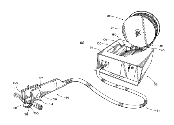
FIG. 1 is a perspective view of an automatic cable tie
installation tool embodying the concept of the present invention,
the automatic tool havlng a dispenser mechanism, a conveyance
mechanism and a remote tool mechanism;
FIG. 2 is a top vlew of a planar ribbon off cable ties
embodying the concept of the present invention;
FIG. 3 is a sectional view of the ribbon in FIG. 2
taken along the line 3 3 of FIG. 2;
FIG~ 4 is a perspective view of the dispenser mechanism
of FIG. 1 with the dispenser's load door belng disposed in the
open position;
FIG. 5 is a top view of the dispenser mechanism o~ FIG.
4 as seen with the dispenser housing removed;
FIG. 6 ls a sectional view of the dispenser mechanism
of FIG. 5 taken along line 6-6 of FIG. 5;
FIG. 7 ls an exploded perspective o~ the dispenser
mechanism of FIG. 5;
FIG. 8 is a partial sectional view of the ribbon and
the ~pper and lower guido plates of the dlspenser mechanlsm as
taken along line ~-~ of FIG. 9;
FIG. 9 is a partial sectional vlew of the dispenser
mechanism of FIG. 5 taken along line 9-9 of F~G. 5;
FIG. 10 is a partial sectional view of the upper and
lower guide plates of the dispenser mechan.ism of FIG~ 5 as taken
along line 10-10 of FIG. 5;
FIG. 11 is a front v~ew of a manifold block of the
-- 7 --
. .:
,~. , :
... : ~ .. .
. ' ;
dispenser mechanism;
FIG. 12 is a side view of the manifold block of FIG.
11, not showing the pneumatic fittings of the manifold block;
FIG. 13 is a sectional view of the maniold block of
FIG. 12 as taken along line 13-13 of FIG. 12
- 7a -
~.
'~ ' ' ' , ' , : '' - -
~ 7~3~
FIG~ 14 i~ a back view of the manifold block o~ FIG. 11
~howing the funnel shaped entrance of the exit orifice of
the mount.ing tube.
FIG. 15 iB a front view of the conveyor hose of the
conveyance mechanism, having one end broken away to show
therein contained pneumatic tubes and electrical cable.
FIGo 16 is an end view of the dispenser end of the
conveyor hose of FIG. l~o
FIG. 17 is an end view of the tool end of the conveyor
hose of FIG. 16.
FIG. 18 is a side view of the remote tool mechanism of
FIG. 1 with half of the housing of the remote tool removed,
with parts removed to show the drive gears, the retaining
slide; the brake mechanism and the lower jaw mechanism~
FIG. 19 is a ~ide view of the remote tool of FIG~ 1
with half of the housing of the remote tool removed~
FIG. 20 is an exploded view of the internal mechani~ms
of the remote tool of FIG. 1~.
FIG. 21 is a ~ide view o~ one o~ the bxake pads utllized
in the remote tool mechani~m 18.
FIG. 22 is a top view o~ the brake pad of FIG. 21.
FIG. 23 is a block diagram, showing the positional
relationship of FIGS. 23A-23E.
FIGS. 23A-23E are schematic diagrams that collectively
define the electrical/electronic circuitry used to control
the automatic tool of FIG. 1~
~8--
De~cr~ption_of the Prefe.rx~d Embodiment
An automatic cable tie installation tool embodying the
concept of the present invention is generally indicated by
the numeral 30 in the accompanying drawiny~. As best ~een
in FIG. 1, the automatic tool 30 incluaes a dispenser mechan-
ism 32, a conveyance mechanism 34 and a remote toQl 36.
The dispenser mechanism 32 accepts a ribbon 38 of cable
ties 40 and ~equentially dispen~es individual ties 40 to
conveyance mechanism 34. The conveyance mechanism 34
delivers the indi~idu~l ties 40 to remote tool 36. Remote
tool 36 then positions each tie 40 around a bundle of wire
or the like, tensions tie 40 to a predetermined value and
then severs thé tail of tie 40. It should be understood
that the concept-of the present invention is not limited to
th provisio~ of a remote tool, but encompasses an automatic
tool 30 wherein the dispenser 32 is integral with and ~up-
ported by tool 36.
The ribbon 38, as best seen in FIGS~ 2 and 3, includes a
plurality o cable tie6 40 each mounted at their heads 42 ko
~trip portion 44 by ~ tab 46. The ties 40 are equally
~paced along the length of fitrip portion 44 with each cable
tie's medial l~ngitudinal axis being in parallel disposition
to each other tie 40 and each tie 40 forming a right angle
with th~ longitudinal axi~ of strip portion 44.
The ties 40 are of normal one piece construction having
a locking head 42 and a strap 48 that inserts into head 42
to be locked therein. As seen in FIG. 9, the head 4. of
each tie 40 tapers from a greater width in the plane of
~trap 48 to a smaller width i~ a parallel plane above the
strap 48. The thickness of each head 42 of each tie 40 is
appr~ximately three times the thickness of strap 4B~ The
~trap 48 being approximakely equal in thickness ~o ~trip
portion 44 ~Id being located substantially in the ~ame
pla~e. ~ach head 42 thus projects above the ~trap 48 and
&trip portion 44; the heads 42 4f the plurality of ties 40
~ 7~17~
in ribbon 38 forminy.a projectiny discontinuous ridge running
the length of ribbon 38.
The ties 40 are connected to ~trip portion 44 by tabs
46. Each tab 46 is located in the same plane as strip
portion 44 and is of approximately the same thickness. The
tabs 46 are trapezoidal in shape, tapering from a wider end
ad~acent strip portion 44 to a narrower end adjacent head
42.
The strip portion 44 is defined by two parallel edges
50; the inner edge 50 being contiguous to tabs 46 and the
outer edge 50 having no substantial discontinuities. The
width of strip portion 44 is approximately twice the length
of head 42. The length of strip portion 44 is defined by
the length of ribbon 38. The thickness vf strip portion 44
i~ sized dependent upon its material, to provide sufficent
flexibility to allow ribbon 38 to be coiled on a dispensing
reel but with sufficient rigidity to define a substantially
planar ribbon 38.
Positioned on both planar sides and along the length o
strip portion 44 are alignment guides 52. Alignment guides
52 each include two square projecting surfaces 54~ The
surface~ 54 are formed in line with each abutting a diferent
edge 50 of strip portion 44. The sufaces 54 are each approx-
imately one third the width of strip portion 44, the two
surfaces 54 together defining a channel area 56 intPrposed be-
tween the two surfaces 54 khat i8 approximately one third
the width of strip portion 44. The surfaces 54 have opposing
inner sides that define two alignment eages 58. The alignment
edges 58 are colinear with the respective alignment edges 58
of each successive alignment guide 52 on strip portion 44
and are parallel to each other, defining a discontinuous
alignment channel 60 running the length of ~trip portion 44.
The alignment edge~ 58 allow accurate lateral alig~ment of
ribbon 38, alignment edges 58 providing opposing alignment
surfaces thus allowing positioning cf ribbon 38 in both
-10-
~ 7~
latexal directionfi. Succe~sive alignment guides 52 are
equally fipaced along the length of strip portion 44 ha~ing
two ties 40 interposed therebetween.
In preferred form, each alignment guide 52 on one
planar ~ide of the strip portion 44 is juxtapo~ed with a
reflecting alignment guide 52 on the oppo~ite planar ~ide of
the ~trip portion 44, thus defining two alignment ¢hannels
60 positioned on opposing planar ~ides of strip portion 44.
Ribbon 38 is preferably manufactured as a one piece
thermoplastic ribbon; tie~ 40, tabs 46 and strip portion 44
all being integrally molded of the same material. Manu-
facture of ribbon 38 is ef~ected by molding incremental
lengths of ribbon 3B and joining the distal end o~ strip
portion 44 of each incremental length of ribbon 38 to the
distal end of strip portion 44 of a successi~e incremental
length of ribbon 38. In preferred construction~ the con-
nection of the incremental lengths of ribbon 38 is accomp-
lished as each new incremental length of ribbon 38 is molded;
the trailing end o~ ~trip portion 4~ o~ the last molded
.incremental length of ribbon 38 being held wi~h~n the in-
cremental ribbon mold, while the strip portion 44 of the
next ~ucceeding incremental length of ribbon 38 is fixedly
molded to this trailing end. The ~trip portion 44 of each
increme~tal length of ribbon 3B can be molded with bores
disposed proximate the trailing end o~ each strip portion 44
whereby material from the next ~ucceeding molded incremental
length of ribbon 38 will flll the bores and provide a secure
connection between the contiguous incremental lengths of
ribbon 3B. It ~hould be underst~od that other methods of
3Q securely mounting cable ties to an aligning ~trip also are
within the concept of the pre~ent invention, For example,
discretely manufactured ca~le tie~ may be ~ecured to a
carrier ~trip in the ~ame structural configur~tion as described
above by adhesive or by i~terference fit between each tie
and the carrier ~trip.
--11--
Referring now to FIGS~ and 5, diRpen~er mechani~m
32 generally includes a reel mechani~m 6~ for providing
ribbon 38 to dispenser mechanism 32, a grooved cylinder 64
that accurately positions and carries the individual ties
40, an index mechanism 66 that drive~ the cylinder 64, a
guide mechanism 68 that coopera~es with the ~trip portion 44
of ribbon 38 to accurately po~ition the ribbon 38 in di~-
penser mechanism 32, a knife 70 that separates individual
ties 40 from ribbon 38, and a transfer mechanism 72 that
delivers discrete sPparated ties 40 upon demand.
The dispenser mechanism 32 i8 enclosed in a housing 74.
The housing 74 having a reset button 76, a load button 78,
a light emitting diode 80 for indicating a check loading
condition, a light emitting aiode 82 for indicating a check
hose/empty ¢ondition9 a light emitting diode 84 for indicating
a power on condition and an audi~le warning buzzer 86;
all proximately located on the front ~i~e of housing for
ease of inspection by the operator of automatic tool 30.
Also located on the ~ront o housing 74 i8 a connector poxt
88 designed to mate with conveyance mechanism 34.
The reel mechanism 62i as best ~een in FIGS. 1 and 4, is
mounted on dispenser housing 74 vf dispenser mechanism 32
The reel mechani~m 62 includes a bracket 90 mounted to
dispenser housing 74 by suitable fasteners at its lower end
and having a reel arm 92 non-rotatably mounted in a bore at
it~ upper end. The reel arm 92 is positioned with its axis
parallel to the axi~ of cylinder 64. The reel arm 92 i~ a
~mooth cylindrical bar sized to accept and rotatably mount
reel 94 that carries the coiled ribbon 38. ~he di~tal end
~f reel arm 92 carries a removable retaining pin 96 which
limits the outward movement of mounted reel 94O A ~pring
98 i~ coaxially carried on reel anm 92, being 6ized to apply
a tensioning force against reel 94 to re~train free rota~ion
of reel 94 while allowing the cylinder ~4 to withdraw ribbon
38 from reel 94O The reel 94 i~ mounted ~n reel ~rm 92
. ,_
having ~trip poxtion 44 placed inwardly and aligned wl~h
guide mechanism 68.
As seen in FIGS. 4, 5 and 9 a pivotally mounted dispenser
load door 100 is mounted above ~ylinder 64. The door 100
h s a substantially cylindrical forward contour 102 that
helps guide ribbon 38 into cylinder 64 and an angular ~h~ped
back contour 104 that mate~ with cover 236. ~he door 100
can be pivoted upwardly from cylinder 64 to facilikate
loading and downwardly into position over the cylinder 64 to
act as a guide for rihbon 38 and to shield cylinder 64 from
the introduction of foreign objects. Mounted proximate door
100 is an electrical load door safety ~witch (not ~hown~
that provides a signal indicating whether door 100 is open
or closed. The load door 100 is providP~ with a lat~h 106,
as seen in FIG. 5, that selectively locks the door 100 in a
closed position by insertion of a pin through a first mounting
wall 108. The load door safety switch can be positioned in
a known manner to sense whether door 100 i5 iockea in the
closed posi.tion. Al~o pxoviding guidance to ribbon 38 is an
inclined ramp 110 of housing 74 that projects from the kop
of hou~ing 74 towards cylinder S4. ~he ramp 110 helps
support and guide ribbon 38 as it i8 drawn into mating
engageme~t with cylinder 64 from reel mechanism 62.
As seen in FIGS. 5 and 7, grooved cylinder 64 is rotatably
mounted hetween first mounting wall 108 and a ~econd mounting
wall 112 on bearings (not shvwn) by an axle 114~ The axle
extends through a bore in fir~t mounting wall lOB and presents
a splined end (not shown) by which it is secured to index
mechanism 66. The cylinder 64 has a plurality of ~plines
118 that define a plurality of grooves 120. The groo~es 12V
run the length of cylinder 64 being lightly greater in
depth ~han ~he height of head~ 42 of ties 40 and being
Elightly l~nger than the length of ties 40~ A~ seen in FIG.
9, splines 118 preBent a contour ha~.ing flat surface portions
119 that fac~litate the mating accepta~ce of head~ 42 of
-13- .
~7~
ties 40; the width o the groove~ 120 at thelr deepe~t poirlt
being ~lightly wider than the greatest width ~ tie 40.
Ribbon 38 i~ driven by the m~tlng intera tion of heads 42 of
ties 40 with gxoove~ 120; grooves 120 accurately longitud-
inally positioning and driving the head 42 of each cable tie
40, thereby lonyitudinally positioning and driving ribb~n
38.
~ ~he index mechanism 66 includes a dispensex air motor
122, a gear adaptor 124t drive gears 126, drive shaft 128,
~ingle revolution clutch 130, clutch drive adaptor 132,
planetary gear assembly 134 and an index ring 136. The
index mechanism 66 rotates the cylinder 64 in accurate
increments of fractions of one revolution in order to
sequentially carry ribbon 38 to knife 70 and transfer
mechanism 72. In preferred construction the eylinder 64
presents twenty-five grooves equally ~paced around its
circumference, each o~ which is sized relative to ribbon 38
to carry one tie 40. The cylinder 64 in FIG. 7 being de-
picted having nineteen grooves for clarityO Thus in order
to sequentially present each ti0 40 to the st~tionary trans-
~er mechanism 72, cylinder 64 must be accurately rotated
1/25 of o~e complete revolution.
Dispenser air motor 122 i~ a standard pneumatic motor
and is mounted between first mounting wall 108 and a third
mounting wall 138. Application of pre~suri~ed air to dis-
penser air motor 122 drives the motor'~ shaft 140 which i~
non-rotatably affixed to gear adaptor 124O The gear adaptor
124 rotatably drives intermeshed drive gear~ 1420 the second
of which in turn rotates dri~e ~haft 128.
The dispen~er air m~tor 122, through dri~e shaft 128,
supplie~ continuou~ rotational input to ~ingle revo~ution
clutch 130 which ~electively transfers rotational motion to
planetary gear assembly 134 through clutch drive adaptor 132
in one revolution increments. The single revolution clutch
130 is a ~andard component having a holenoid actuator 146
and a wrapped ~pring clutch 148. Application of electrical
-14-
~ 7~
power to ~oleno:id 146 actuate~ clutch 148 which drives
clutch drive adaptor 13~ for exactly one revolution. It
should be under~tood that the use of other component~ to
supply accurate incremental rotational input, for example
the use of an electrical ~tepper m4tor, are consistent with
the concept of the pre~ent invention.
The clutch drive adaptor 132 drives the planetary gear
assembly 134; the forward end of clutch driver adaptor 132
non-rotatably mating with the sun gear of the first stage of
planetary gear assembly 134. The planetary gear assembly
134 is constructed of standard components manufactured by
Matex Products, Inc., Cleveland, Ohio, consisting of two in
line 5:1 planetary gear stages, Model~Nos. 75-MSA and 75-M5B,
separated by a standard coupling ring, Model No. 75CRC that
are designed to reduce one revolution of input supplied by
clutch drive adaptor 132, to 1/25 of a revolution of output
which i8 then supplied to cylinder 64. Each planetary gear
stage includes an axially disposed sun gear 6urrounded by
three intermeshing planetary gears that intermesh wi th an
encircling ring gear. The planetary gears o~ sach stage are
each rotatably carried on a ~pider. Input supplied by the
clutch drive adaptor 132 i~ supplied to the fir~t stage ~un
gear which drives the first stage planet.ary gears, rotating
the first stage spider. The first ~tage spider non~rotatably
carries the second ~tage sun gear; rotation of the flrst
stage ~pider effecting rotation in the second stage sun
gear. The second ~tage sun gear drives the second stage
planetary gears within the intermeshed second stage riny
gear and thus rotates the ~econd ~tage ~pider, The ~econd
stage ~pider presents a ~plined outpu~ 150 that matingly
connects with the ~plin~d e~d of cylinder axle 114.
~he planetaxy gear as~embly 134 is non-rotatably affixed
to first mounting wall 108 by a detachment mechani m 152 in-
cluding index ring 13~ and a locking pin as~embly 156. The
index ring 136 i~ affixed to the ring gear~ of both ~tages
--15--
~ 7~ )
of planetary gPar as3embly 134 by fastener~ 158 that project
~hrough bores in the ring geax6 and planetary gear a~sembly
134 at counter-bores 160.
The index ring 136 has a plurality of index bores 162
equally spaced around its circumference that accept locking
pin assembly 1560 In order to maintain the proper alignment
between clutch 148 and grooved cylinder 64, ~he number of
index bores 1~2 should be any multiple of the actual ~un-to-
planet reduction in a ~ingle planetary stage, for example if
1~ single stage total reduction is 5~1, then sun-to-planet
r~duction i8 actually 4:1 and any multiple of 4 holes in
index ring 136 would provide a correct number of equally
spaced index bores 162.
The ring gears of planetary gear assembly 134 an~ index
ring 136 can be sele~tively locked from rotation by locking
pin assembly 156. Initial alignment of cylinder 64 relative
to single revolution clutch 130 i effected hy correct~y
aligning cylinder 64 with orifice 224 and exit ~rifice 246
while locking pin assembly 156 locks planetary gear assembly
134 from movement and while ~et scxews 163 are loosened
allowing relative positional movement between clutch drive
adaptors 132 and clutch 148; and by subsequent tightening
of ~et ~crews 163 to secure clutch drivs adaptor 132 to
the output end of clutch 148. When planetary gear assembly
2~ 134 i~ so aligned and locked, the proper alignment between
clutch 148 and cylinder 64 is ensured, rotation of clutch
drive adaptor 132 resulting in positive movement in ~plined
output 150 of planetary gear assembly 134. Di~engagement of
the locking pin assembly 156 allows the free rotation of the
ring gear~. ~hen the ring gear~ are free ~o rotate; the
grooved cylinder S4 i8 no longer airectly driven by the
clutch drive adaptor 132 and cylinder 64 i6 ~ree to rotate.
Rotati~n of cylinder 64 merely results in the rotation of
the ring gear5 of planetary gear a~sembly 134O Upon engage
~ent of the locking pin assembly 156 in any of ~he index
bores 162~ cylinder 64 i5 again aligned with and dixectly
d~iven by clutch 148. Thus, cylinder 64 can be selectl~ely
disengaged from index mechanism 66, manually rotated during
the loading o~ ribbon 38 and engaged to index mechanism 66
in the proper aligNmentO
Mounted to the first mo~nting wall 108 in a position to
matingly insert into index bores 162 iB locking pin assembly
156 which includes a pin 164, a retaining ring 16B, a
washer 170~ notched spacer 172~ block 1~4, mounting angle .
176, spring 178 and a handle 180. The pin 164 has at its
upper end threads 182 that mate with a corresponding threaded
bore in handle 180. Towards the lower end of pin 164 are
lugs 184 positioned in a line normal to the axis of the pin
164 and a retainer groo~e (not ~hown) positioned ~elow lugs
184. The spacer 172 and block 174 include a cylindrical
spacer 172 affixed to a metal block which has a bore to
communicate with spacer 172. The spacer 172 has a pair of
opposing shallow notches 188 and a pair of opposing deep
notche~ lgO, b~th pair~ being ~ized ~nd positioned to mate
with lu~s 184 o~ pin 164~ Mounting angle 176 includes an
angle iron mount that iB affixed to first mounting wall 108
having a bore to accept pin 164 which is positioned to
communicate with the bore in spacer 172 and block 174 and
having a counter-bore to accept handle 180~ Spriny 178,
washer 170 and retaining ring 16`8 are of normal construction
and are ~ized to be carried on pin 164.
Washer 170 i~ carried on the lower end of pin 164 where
it i6 retained between retaining ring 168 and lug~ 184. Pin
164 insert~ through ~pacer 172 and block 174, mou~ting
angle 176 and spring 178, where it is threadingly affixed to
handle 180. The block 174 is positioned along and adjacent
to the mounting angle 176 ~o as to be non-rotatingly mounted.
Spring 178 bia~es pin 164 upwardly against ~he notched
~pacer 172. By exerting foxce on handle 180 against th~
bias of pin 164 and rotating handle 180, lugs 184 c~n be
. -17-
r7~
placed matingly within deep notc~e~ 190 ~o ~horte~ the
affective length of locking pin a~sembly 156 or placed
within shallow notche~ 18B to lengthen locking pin assembly
156. Thus, pin 164 can be ~electively inserted into index
bores 162. An electrical ~witch ~not shown) i8 mounted in a
position to provide a ~ign~l indicating whether or not pin
164 is lo~ked in one of the index bores 162; the electrical
~witch being of normal construction, having ~n actuation arm
the movement of which actuates the switch to an off or on
~tate. The actuation arm can be disposed tG interact with
washer 170 to sense whether pin 164 is locked in an index
bore 162.
Referring now to FIGS. 7, 8 and 10, guide mechanism 68
includes an uppex guide plate 194 and a lower guide plate
196 that together matingly define an I-shaped channel i98
having flanges 200 that each provide alignment edges 202
sized to matingly carry and position strip portion 44 of
ribbon 38. The upper and low0r guide plates 194 and 196 are
positioned parallel to and af~ixed to first mounting wall
108, adjacent cylinder 64. ~he upper and lower guide plates
. 194 and 196 have complimentary edges 204 that togethex
define the path of ribbon 38 and strip portion 44.
As seen in F~GS. 7 and 10, upper guide plate 194 i~
positioned above the cylinder 64, its edge 204 ha~ing a
forward bluntly curved portion 206 that i8 po~itioned away
from lower guide plate 194 to define a mouth 208 to in-
itially accept and guide rib~on 38 into position with
cylinder 64 and channel 198, an intermediate portion 213
that follow~ the curve of cylinder 64 to position tie~ 40
thereon and an inclined portion 212 projecting downwardly
defining the path o~ fitrip portion 44 after ties 40 have
been ~evered. In the face of upper guide plate 194 adjaeent
cylinder 64 i~ a knif~ kerf 214, Rnife kerf 214 projec~
downwardly at approximate~y ~ forty five degree ~ngle to ~he
horizontal plane, in a line that inter~ect~ the center of
-18~
axle 114 of cylinder 64. Th~ lower corner o~ upper yuide
plate 194 presents a notch 216 onto which is mounted a
photoelectric strip sensor positioned to detect the absence
of strip portion 44 of ribbon 38.
The lowex guide plate 196 i5 positioned below upper
guide plate 194 its edge 204 having a forward p~rtion 218
~hat approximates the inner circumference of grooves 120 and
~ an inclined portion 220 that matingly follows edge 204 of
upper guide plate 194. ~he lower guide plate 196 also has a
knife kerf 222 positioned in line with upper guide plate's
knife kerf 214 on its surface adjacent the cylinder 64 and
an orifice 224 of transfer me~hanism 72 that is positioned
to align with one of the grooves 120 when the gro~ve 120 is
- in the horizontal plane that intersect~ cylinder axle 114.
Knife 70 includes a blade 226 adjustably mounted in
knife kerf 214 by screw 228 that attaches hlade 226 to a
rod (not shown). The rod is slidably mounted in a bore
through first mounting wall .lO8 and upper guide pl~te 194
that communi.cate~ with the knife kerf 214. A set ~crew 230
i5 mounted transver~e to the ro~ in first mounting wall 108
in such a manner to interferingly secure the rod from move-
ment. Positional adjustment of knif2 70 is accompli~hed by
loosening set screw 230 and repositioning the rodO The
blade 226 has a medical mounting slot 232 for accepting the
screw 228 and an angular cutting edge 234 for ~evering tie
40 from ribbon 380 The knife blade 226 is positi~ned trans-
verse to the ribbon 38, lying in a plane parallel to the
face of upper and lower guide plates 194 and 196, between
upper and lower guide pl~tes 194 and 196 and cylinder 64.
The a~gled tip of cutting edge 234 projects past the channel
198, presenting an angled cutting edge 234 normal to the
outer end of head 42 of tie 40. Movemen$ of tie 40 past the
angled cuttiny edge 234 result~ in ~ slicing cutting action
which cleanly ~eparate~ tie 40 ~rom ribbon 38.
19
7~
The accurate late~al positioning of heads 42 of ties 40
relative to ~he hlade 226 i~ ensured by the aligning co-
operati~n of alignment guides 52 on strip portion 44 of
ribbon 38 and alignment edges 202 of I-shaped channel 198 as
~een in FIG. 8. Additionally, the ~hape of tab 46, being
smaller in width near head 42 of tie 40 facilitate~ the
~eparation of head 42 from tab 46 close to the head 42.
. _
- Fine adjustments to the position of blade 226 relative to
head 42 of tie 40 can a~so be made by set scxew 230, allowing
the operat~r to compensate for inherent tolerance variations.
Thus the pre~ent invention ensures that the discrete cable
-~ ties 40 pro~ided by dispenser mechanism 32 present a cable
tie 40 having a substantially smooth head 42.
Positioned in mating proximity to cylinder 64 is cover
236. Cover 236 is a partial section of a cylindrical shell
having its inner diameter sized to mate with the outer
diameter of cy~inder 64. ~over 236 i~ egual in length to
cylinder 64 and extends from a fixst edge 238 at approx-
imately the top of cylinder 64 to second edge 240 approx-
imately one hundre~ and forty degrees around th~ c~linder
64. The first edge 238 has an angled contour~ a~ seen in
FIGS. 4 and 7, which facilitates the guidance of heads 4~ of
ties 40 into grooves 120 of grooved cylinder 64. The first
edge 238 is angled to contact head~ 42 of ribbon 38 before
it contacts ~traps 48 of cable ties 40. Thus, as grooved
cylinder 64 rotates drawing ribbon 38 inward, first edge 238
initially guides and inserts head 42 of each incoming tie 40
into its respective groove 120 and subsequently guides each
strap 48 into the same groove 120.
The cover 236 is mounted on a hinge 242, as seen in
FIG. 6, to allow cover 236 ts be pivoted outwardly from
cylinder 6i to fa~ilitate the removal of j~n~d material
~rom cylinder 64. ~h8 cover 236 does not extend past the
. bottom of cylindex 64, thus severed kie~ 40 pa~sing beyond
transfer mechani~m 72 are eventually dropped from the bot~om
-20-
of cylindex 64 and do nvt interfere with contiIlued ~unction-
ing of dispenser mechani~m 32~ The cover 236 i~ positioned
near enough to cylinder S4 to non-interferingly allow move-
ment of cylinder 64 while ~ealingly covering a number of
grooves 120 to therein define a number of channel~ 244.
Transfer mechanism 72 includes a source of fluid pxessure
(not ~hown) which supplie~ fluid pressure to orifice ~24
that i5 positioned to introduce a primary jet of air into an
aligned tran~fer channel 245 a~ it is aligned with an exit orifice
246 to eject a tie from channel 245. In preferred form,
exit ori~ice 246 and orifice 224 are positioned at the nine
o'clock position of grooved cylinder 64 9 looking toward
index mechanism 66. Orifice 224 in lower guide plate com-
municate~ with a conduit bore 248 in fir~t mQunting wall 108
that carries a standard fixture (not shown). An air supply
hose tnot shown~ is attached to the fixture to supply fluid
pressure to orifice 224. The exit orifice 246 i5 positioned
, on seco~d mounting wall 112, in line with transfer channel 2~5
and orifice 224. Referring now to FIGS. 11 to 14, exlt
ori~ice 246 is carried in the forward end of mounting tube
250 and i~ ~unnel shaped to ensure ease o~ entry of tie 40
as it i8 ejected from trans~er channel 245 through khe exit
orifice 246.
Mounting tube 250 i~ molded to axially define a di~-
penser receiving tube 252. The mounting tube 250 is ~haped
to mate with a bore in 6econd mounting wall 112 and a bore
in manifold block 2540 The mounting tube 250 has a key 256
that mates with a 810t in the bore of second mounting wall
112 to ensure proper orientation of mou~ting tube 250 and
dispenser receiving tube 252 formed ~herein. The dispenser
receiving tube 252 ha~ a rectangular cross ~ection that
mate~ with head 42 of tie 40 to orient tie 40 for later
positionins in remote tool 36. ~he mounting tube 250 i~
positioned flush to th~ inner ~urface of ~eco~d mounting
-21-
~ t~
wall 112 at lt~ forward end and projec~ outwardly o~ ~he
outerface 258 of manifold block 254 at its reward end.
Towards the exit ori~ice 246 in mounting tube 250
is positioned a gate mechanism 260 ~or selectively sealing
the entrance to the dispenser recei~ing tube 252 and a
secondary air pressure ~upply orifice 261, being ~upplied in
known manner with a source of pressurized air, or applying
air under pressure between the gate mechanism 260 and ~ tie
40 carried in the dispenser receiving tube 252. It should
be understood that the provision of a dispenser xeceiving
tube 252 and a gate mechanism 260 is not absolutely neces-
sary to the practice of this invention. Also within the
concept of the present invention would be to utilize the
primary air bur~t of transfer mechanism 72 to propel a cable
: 1~ tie 40 from transfer channel 245 to conveyance mechanism 34
- and therethrough to remote tool 36. The provision of dis-
penser receiving tube 252 and gate mechanism 260 enhances
the operation of the present invention by allowiny concurrent
provision and application of a ~ble tie 40 by remote tool
36 and incremental rotakion o groo~ed cylinder 64 by index
mechanism 68 to advance the subsequent tie 40 into aligned
position for su~sequent provision ~o remote ~ool 36; thus
minimizing the l~ngth of the cycle of operatlon o~ the auto-
matic tool 30. Additionally, ~he provision of gate mechanism
260 and secondary air pressure supply orifice 261 eliminates
the possibility of sealing pro~lems between cover 236 and
grooved cylinder 64 (the use of ~ sin~le air burst neces-
~itating a tighter seal to ensure delivery of a tie 40 t~
remote tool 36) a~d eliminate~ any problems of pneumatic
loading of grooved cylindex 64 due to pressurization of
transfer channel 24~.
As fieen in FIG. 13~ the gate mechani~m 260 includes a
pi~ton 262 that stroke~ its rod 264 between an open a~d
closed positio~; rod 264 being biased towaxds ~he open
position by a ~pring 266. When air pres~ure i8 ~upplied behind
-2~
pi~on 262 in chc~er 26~ rod 264 i~ ~troked to the closed
position, projecting rod 264 through a bore in mounting tube
250 and dispenser receiving tube 252 to seal dispenser
receiving tube 252 from exit orifice 246 and aligned channel
244. When the supply of pressurized air is terminated, the
hias o:E spring 266 returns rod 264 to the open po6ition
allowing communication between trans~er channel 245 and
dispenser receiving tub~ 252. The piston 262 is mounted
within a bushing 270. A gate 272 having an O ring seal 274
i~ fastened to manifold block 254 to define chamber 268.
The manifold bloc:k 254 that mc>unts gate mechanism 260 and
. mounting tube 250 presents an outer face 258 that is structured
to mate with conveyance mechanism 34. Conduits (not shown)
respectively connect gripper motor air supply orifice 276,
jaw cylinder air supply orifice 278 and retainer slide
cylinder air supply orifice 280 to fittings 282 that are
connected to air supply tubing (not shown~. An electrical
connector 284 is provided to mate with a curresponding
connector in conveyance mechani~m 34.
As seen in FIG. 7, a~ter tie~ 4û are severed from
ribbon 38, the remaining ~trip portion 44 passes down the
inclined portion of channel 198 where it exit~ channel 198.
Positioned transverse to strip portion 44 proximate the egress
of channel 198 are the blades 286 of chopper n~echanism 288.
The chopper mechanism 288 is a standard ~omponent, blades
286 of which are actuated by the sele~tive application of
air pres~ure to chopper mechanism 2B8.. The blades 286 are
po~itioned to fiever the exhausted strip portion 44 at regulax
interval~, the severed pieces o~E strip portion 44 bein~7
cauyht in a container positioned be~ ow the chopper mechanism
288 .
The conveyance mechanism 34 best depic:ted in 15, 16 and
17 include~ ~ flexible conveyor hos~ 290 which contains a
gripper motor air supply tube 292, jaw cylinder air ~upply
tube 294, a retainer slide cylinder air supply tube 296 " tie
--23--
~ 7~
conveyor tube 298, and ~n electrlcal logic cable 300.
~ocated at opposing ends of conveyor hose 290 are a dispenser
hose disconnect 302 and a remote tool hose disconnect 304.
The flexible conveyor hose 290, in preferred form has a
polypropylene spiral spine 306 coated with a polypropylene
sheath, the pipe being of ~ufficient rigidity to protect the
contained tubes while retaining sufficient ~lexibility to
allow easy manipulation of remote tool 36.
Tubes 292t 294 and 296 are thermoplastic pneumatic
~upply tubes of normal construction. The logic cable 300 is
of normal construction for transmitting electronic signals
from sensor~ located in remote tool 36 to the control logic
located in dispenser mechanism 32. The logic cable 300 only
- transmits low voltage and current to remote tool 36 thus
presenting no safety hazard to the operator of remote tool
36~
Tie conveyor tube 298 is construc~ed with a rectangular
cro~s-section complimentary to the cross-section of head 42
of tie 40. The tie 40 i~ presented to the conveyor tube 298
by di~pen~er mechani~m 34 in an oriented po~ition due to the
initlal po~itioning by the cooperation between ribbon 38,
cylinder 64 and rectangular di~penser receiving tube 2520
Thus each tie 40 i8 transported fxom dispenser mechani~m 32
to remote tool 36 in the same oriented position.
The dispenser hose di6connect 302 and the remote tool
hose disconnect 304 each removably pneumatically and elec-
trically connects the above described tubes 292, 294, 296
and 298 and cabl~ 284 to the respective tubes and cables of
the dispenser mechanism 32 and remote tool 36.
Conveyance of tie 40 from dispenser receiY~ng tube 252
and through conveyance mechanism 34 i8 accomplished by
application of a ~econdary application of pressurized air
through air ~upply orifice 261 located behind hea~ 42 of ~ie
~0 and in front of rod 264 of clo~ed gate mechani~m 260.
24-
~ 7~t~
Referxing to FIGS~ 1, 18, 19, and 20, remote tool 36
~enerally includes a housi~g 309 ~ized to ~acilitate hand
manipulation, an upper jaw 310, a lower ~aw 312, ~aw trigger
:~ 314, a remote tool hvse connection 316 opposite the jaws for
mating attachment to conveyance mechanism, a push-button
abort switch 317 and a remot~ tool trigger 318. The remote
tool trigger 318 when depressed translates a magnet carried
thereon in~o operational proximity to a Hall-effeCt sensor
that provides an actuation signal.
A mechanism for recei~ing the oriented tie 40 from con-
veyance mechani~m 34 includes a steel tie receiving tube
320, a tie brake mechanism 322 and a retaining slide mechanism
324.
The rectangular tie receiving tube 320 receives the
oriented tie 40 provided by conveyance mechanism 34 and
guides it strap first to tie brake mechanism 322 into the
oriented position shown in FIG. 18. Mounted in the foxwaxd
- end of the r~ceiving tube 320 is a guide 32S that dir~cts
the strap o~ eaah tie 40 downward towards th~ upper jaw
310. A photoelectric tie sensor 326 is mounted to the
receiving tube 320 near the entrance of receiving tube 320
to provide a ~ignal indicating when a tie 40 has entered the
receiving tube 320.
The tie brake mechanism 322 includes two bxake pads 328
2~ located on opposing ~ides of receiving tube 320. The brake
pads 328, as.~een in FIGS. 20, 21 and 22~ are mounted in
810ts 330 i~ receiving tube 320 and are biased inwardly by
resilient rubber pads 332. ~he brake pad~ each have a wedge
~haped brake ramp 334 and a gripping tab 336 that project
into receiving tube 320. The brake pads 328 are positioned
proximate the jaw end of receiving tube 320 with ramps 334
pro~ec~ing inwardly into receiving tube 320; both ramps 334
Rlope inwardly towards the jaws and together increasingly
constrict the cro~s ~ectional area of receiving tube 320 in
the direction of movement of tie 40. The ramp~ 334 grad-
~ 7~7 ~
ually ~low the air propelled tie 40 as it ~lides acro~s the
increasing corlstriction of opposing ramps 334, r~mps 334
expanding against the bias of rubber pads 332. After the
tie 40 pa~se~ over the ramps 334, it is resiliently stopped
S from forward movement and gripped from the ~ide by grippiny
tabs 336 which position and resiliently hold tie 40 later-
ally in place while the forward edge~ of inwardly biased
ramp~ 334 pr~vent xetrograde movement of tie 40. ~he
gripping force applied by brake pads 328 is not of ~u~fi-
cient force to interfere with the ejection of tie 40 by the
secondary air burst.
As best seen in FIG. 18, retaining slide mechanism 324
includes pneumatic retainer ~lide cylindPr 338 having a
shaft 340 that is connected to a connecting link 342 by a
:15 length adjusting spacer 341; connecting link 342 in turn
driving a retaining ~lide 34~. Retainer slide cylinder 338
is selectively supplied fluid pressure by air supply tube
296; cylinder 338 being a single acting pneumatic cylinder
that is biased towards a contracted state~
The retaining ~lide 344 is mo~ably positioned paral.lel
and contiguous to the bottom of receiving tuhe 320 with itæ
distal end 34~ being movable between a ~irst position allowing
head 42 of ti~ 40 to be freely removable from receiving tube
320 and a second extended position which secure~ head 42 in
position in receiving tube 3200
Thu~ the application of air pressure to retainer ~lide
cylinder 338 strokes shaft 340 which drives the retaining
~lide 344 to the ~econd position securing head 4~. The
xemoval of fluid pressure from cylinder 33~ re~ult~ in
biased cylinder 338 retracting shaft 340 and moving the
retaining slide 344 to the fir~t position.
~o~itioning of tie 4~ i~ accompli~hed by the opexation
of upper and lower jaw~ 310 and 312~ ~ogether the upper and
lower jaws 310 and 312 have ~ continuous inner circumferential
3~ guide track 350 that accept~ the ~rap 48 9f tie 40 a~ it is
-2S
~L~7~37~
propelled into position thxough reeei~ing tube 320 and
direct~ st~ap 48 around a circumscribed bundle towards th~
locking head 42 of tie 40.
The lower ~aw 312 is pivotally mounted ~n remote tool
36 by pin 352. Jaw trigger 314 is pivotally mounted to
remote tool 36 and connected to the lower jaw 312 by a link
354. Movement of the jaw trigger 314 toward~ remote tool 36
carries link 354 and pivots lower jaw 312 downward to open
lower jaw 312 and allow the insertion of a bundle L The jaw
tri~ger 314 is bia5ed by spring 356 to hold jaw trigger 314
outwardly and bias lower jaw 312 towards a closed position.
Link 354 is mounted to jaw trigger 314 on an eccentric
bolt 358 which allow~ the effective length of link 354 to be
changed by turning bolt 358. The change in effective length
o link 354 allows fine adjustment of the mating fit of
lower jaw 312 to upper jaw 310.
The upper jaw 310 is pivotally mounted ~y screw 360.
The upper end of upper jaw 310 is rotata~ly mounted to arm
362 by pin 364~ The arm 362 i~ affixed to shaft 366 of a
pneumatic j~w cylinder 368. The application of air pressure
by jaw cylinder air supply t~be 294 to jaw cylinder 368
- ~trokes its ~haft 366 outwardly which extend~ ~m 362 pivoting
upper jaw 310 inwardly. The shaft 366 of jaw cylinder 368
is biased towards non-extended position, causin~ arm 362 to
return upon the removal of fluid pressure. The inward
movement of upper jaw 310 drives strap 48 of a tie positioned
thereon, upward through head 42. Thus selective actuation
of jaw cylinder 294 re~ults in threading a tie strap 48 into
locking engagement with it~ head.
Pro~ided in remot~ tool 3~ ~s a gripper mechanism 370
that draws strap 48 through head 42 of t~e 40 until a pre-
determined tension is xeached and then actuates ~ ~nife 372
that cuts strap 48 adjacent the head 42 of tie 40~
The gripper mechani~m 370 include~ a pair of mounting
plate3 374 having xotatably mounted therebetween a ~haft 376
~27-
tj~
that non rotatably mounts a bevel gear 378 and a ~xi~e gear
380. Bevel gear 378 i~ ~electively driven by ~ mating motor
bevel gear 382 carried on the shaft of pnuematic gripper
motor 384. The gripper mot~r 384 being a standard component
that ~upplies rotational power upon the application of air
pressure from gripper motor air supply tube 292. Forwardly
rotatably mounted between mountiny plates 374 iB a ~econd
: shaft 386 that mounts an idler gear 388 in a position to be
driven by drive gear 380 and to drive a gripper gear 390.
The gripper gear 390 i8 supported for relative movement
between a pair of gripper plates 392. The gripper plates
392 are supported for pivotal movement in xemote tool 36
about a pair of pi~ot pins 394 and have a strap guide 396
positioned therebetween and ~paced from gripper gear 390 a
distance sufficient to permit movement of ~trap 48 of tie 40
therebetween. The gripper gear 390 i~ specially constructed
having a pair of grippex teeth on each of its gear teeth
tha~ effect positive gripping action of ~trap 4~.
Piv~t pins 394 are positioned on the pitch l~ne between
idler gear 388 and gripper gear 390 in order to eliminate
the influence of any external drive force to the gripper
gear 390. The gripper plates 392 permit translational move-
ment of gripper gear 390 relative to strap guide 396 by
means of elongated slots 400 rotatably ~upporting the gripper
gear shaft 40~. Gripper gear springs 404 resiliently bias
the gripper gear 390 to a position closely adjacent strap
guide 396. The geometry of ~lots 400 is ~uch that the
gripping forces on ~trap 48 of tie 40 positioned between
gripper gear 390 and strap guide 396 are increased upon
attempted removal of ~trap 48 ~o a~ to provide a ~elfener-
gizing aspect to gripper gear 390. As gripper gear 390
rotates to permit removal of ~trap 48, a ~orce i~ applied on
gripper gear ahaft 402 urging it to the lowex p~rtion of
~lots 400 whexein gripper geax teeth 398 are clo3er to ~trap
guide 396. The le~gth of strap 48 capable of ~eing ten~ioned
~28-
:~7~
i~ theoretically ininitP du~ to the rotary feed of strap 4
to gripper gear 3gO.
~ cam follower 406 i~ ~upported by a pin 408 mounted
between the forward upper end of gripper plates 392. At the
lower rear of gripper plates 392 are formed knife actuator~
410. Knife actuators 410 mate with arms 412 of knife 372 to
slidingly drive kni~e 372 upon pivotal movement of gripper
plates 392. The knife 372 which is reciprocatîngly mounted
adjacent gripper plates 3g2 present~ an aperture 416 through
which ~trap 48 of tie 40 i~ inserted by upper jaw 310.
Postioned on the forward edge of aperture 416 is cutting
edge 418 which ~evers strap 48 as knife 372 is driven to the
right, as seen in FIG. 18, by pivoting gripper plates 392.
A pivot arm 420 is suitably mounted in remote tool 36
by pivot pin 422. The pivot arm 420 presents a detent 424
positioned to carry cam fQllower 406 and a cam surface 426
below detent 424. The detent end of pivot arm 420 is biased
towards cam follower 406 by a link 428 pivotally mounted to
the upper end of pivot arm 420. The lînk 428 ~electively
applies a variable biasing force to the di~tal end o~ pivot
arm 420 against cam ~ollower 406. The li~k 428 i~ disposed
having a bore in it~ distal end to slidably accept the for-
ward end of rod 430. Medially affixed to rod 430 is a collar
432. A spring 434 is carried on the forward end of xod 430
abuting the ~nd of linX 428 and the collar 432; thus biasing
the rod 430 away from the link 428. The backward end of ro~
430 i8 threaded to carry thumb wheel tenslon control 438
which is rotatably m~unted in housing 308 of remote tool 36.
Revolution of tie tension contxol 438 extends or retracts
rod 430 relative to link 428 and ~hu~ compresse~ or expands
spring 434, proving vaxiable efective bias to pivot arm
420.
~ovement of upper ~aw 310 drive~ strap 48 of the tie 40
through head 42, knife aperture 416 and into engagement with
grippex gear 390 and ~txap guide 3960 The gripper gear 390,
,. ,~
7~
being driven ~y-gripper motor 384, continues to dra~ the
gtrap 48 ~hrough head 40 until tension in ~trap 48 i~ 8uffi-
cient to apply a downward force on gripper plate~ 392 that
overcomes the pre~et bias of pivot arm 420 and pivots the
cam follower 406 out of detent 424 onto cam ~urface 426,
thus pivoting gripper plates 392 countex-clockwise as seen
in FIG. 18. ~he pivoting of gripper plates 392 actuate~
knife 372 and severs the 6trap 48 of tie 40 adjacent its
head 42. The gripper plates 392 are then rotated back to
their original position due to the bias of cam surface 426
again~t cam follower 406~ Mounted at the top of one gripper
plate 392 is a magnet. The magnet is positioned to actuate
a Hall-effect gripper sensor mounted to one mounting plate
374 of remote tool 36, when gripper plate~ 397 pivot back to
their original position after severance of strap 48 is
accomplishedO The gripper sensor thus provides a 6ignal
indicating the cutoff of strap 48.
The operational control of the various working m~chani~ms
of the automatic tool 30 is provided by ~n ele~tronic digital
control as3embly 440 mounted ~n dispenser mechanism 32, best
seen in FIG. 5. A power ~upply 442 provides electrical
power to the control assembly 440 by wires not shown. Based
upon information received from a plurality of sensors located
at various point~ in the mechanisms of the automatic tool
30, control assembly 440 selectively contrDls a plurality of
solenoid actuated pneumatic valve~ 444~ ~olenoid actuated
~ingle revolution clutch 130 and a pluraliky o~ auditory and
visual displays. The control assembly 440 i~ connected to
various ~ensing and controlled components by ~tandard elec~rical
wiring not ~h~wn for clarity.
The pneumatic valves 444 r~ceive pre~ured air from air
supply 446 and individually provide air pressure to variou~
working mechanis~s of automatic tool 30 through ~tandard air
~upply conduits and fixture~ that are not ~hown for clarity.
3~ The individual pneumatic valves are actuated by electronic
-30-
~ 7
logic controlle~ solenoi~s to provide air pressure to the
following respective compon~nt~: a first valve provides a
~econdary air bur~t to orifice 261 to convey tie from the
dispenser mechanism to the remote tool, a ~econd valve
provides air pressure to gripper motor 384 to drive gripper
mechanism 370 and also provides air pressure to gate mechanism
260 to seal aispenser recei~ing tube 252, a third valve
provides air pressure to retainer slide cylinder 338 advancing
retaining slide 344 and securing head 48 of tie 40, a fourth
valve provide5 air pressure to jaw cylinder 368 causing the
upper jaw 31D to pivot and insert strap 48 of tie 40 into
head, a fifth valve provides a primary air burst to orifice
224 of transfer mechanism 72 to eject the tie 40 from trans-
fer channel 245, a sixth valve provides air pressure to
dispenser air motor 122 to drive index mechanism 66 and a
seventh valve provides air pressure to actuate chopper
mechanism 288. Air pressure is not supplied to remote tool
36 constantly, but is only supplied by pneumatic valves 444
when needed to actuate the pneum~tic mechanisms, thus increasing
operator ~aety~
In order to lo~d the dispenser mechanism 320 an operator
secures a reel 94 of ribbon 38 on the reel mechanism 62
oriented so that strip portion 44 i~ aligned wîth guide
mechani5m 680 The load door 100 i~ then pivotsd upwardly to
; 25 allow insertion of the di~tal end of xibbon 38 into grooves
120 of grooved cylinder 64 and channel 198. H~ndle 180 is
rotated until pin 164 i~ removed fr~m it~ index bore 162
a~lowing the cylinder 64 to be freely rotated without des-
troying the align~ent between index mechani~m 66 and cylinder
64~ The ribbon 38 is then positioned over the cylinder 64
with the initial few ties 40 being inserted into ~ucces~ive
grooves 120. The cyllnder 64 is manually rotated until the
- initial tie 40 abut~ the blade 226~ The operator next
insert~ pin 164 into the ~lo~est con~enie~t index bore 162,
pivot~ the door 100 downwardly into it~ closed po~ition and
-31-
~7~
presses the load button 78 located on di~pense~ m~chanism
32.
Acutation of load button 78 provides ~ signal to the
control logic which consequently actuates the sixth valv
providing air pressure to dispenser air motor 122 and pro-
viding rotational input to single revolution clutch 130.
Simultaneously, control a~sembly 440 actuates the ~olenoid
. 146 of single revolution clutch 130 to index the grooved
cylinder 64 1/25 of a revolution. The control assembly 440
continues to index the cylinder 64 until a signal is received
~rom the strip ensor indicating the distal end of the strip
portion 44 has reached the ~trip sensor. At this point, a
se~ered tie 40 i~ positioned in a transfer channel 245
aligned with exit orifice 246 and automatic tool 30 is
~5 loaded and ready to instali ties 40.
Referring now to FIGS. 23 and 23A-23E, the electri-
cal/electronic circuitry used in automatic cable tie in-
stallation .tool 30 assembly of the present invention is
schematically depi~ted. The clrcuitry includes a pow~r
supply PS for supplying direct current to the coils o~ a
plurality of output ~olenoids Sl through S9 which control
various mechanical and pneumatic operations of ~he automatic
tool 30. The power ~upply ~urther provides lower voltage
dircct current for various sensors SNA through SND and for a
logic circuit which is responsive to the output of the
: sensorR to eelectively energiz~ the ~olenoid coils. The
logic circuit is al~o respon~ive to the operation of various
~afety and special functions ~witches, SWl, SW3 - SW6.
More ~pecifically, solenoid S3 controls operation of
retaining slide 344 for retaining hea~ 42 o~ cable tie 40 in
remote tool 36 adjacent upper and lower jaws 310 and 312;
~olenoid S5 control~ application of a primary air burst for
moving cable tie 40 dispvsed in the tran~fer channel 245
past gate mechani$m 260 and into position to be tran~erred
to remote to~l 36 by ~ ~econdary air burst; ~olenoi~ ~1
~ 7
control~ the ~econdary air burst; ~olenvid S2 c~ntxol~
applica~ion o~ air to power yripper motor 384 and gate mechan-
i~m 260; solenoid 54 functions to supply air to jaw cylinder
368 which move~ the upper jaw 310 to thread strap 48 of a
cable tie 40 into it~ locking head 4~; solenoid S6 controls
application of air to dispenser air motor 122; solenoid S8
energizes single revolution clutch 130 to couple dispenser
air motor 122 to grooved cyli~der 64 through planetary year
assembly 134; solenoid S9 controls a cable tie counter; and
~olenoid S7 advances chopper mechanism 288. The trio of
sensors located in the tool include~ ~all-effect sensor SNA
which provides an output in response to actuation of the
tool trigger 38; photoelectric sensor SNB which detects
completion of transmission of a cable tie 40 from dispenser
~5 mecha~ism 32 to remote tool 36; and a ~all-effect sensor SNC
positioned to detect completion of ~utoff of the excess
threaded strap 48 of a tensioned cable tie 40. A fourth
sensor, photoelectric sensor SND, is disposed in dispenser
mechanism 32 to detect the absence of ~trip portion 44 o~
ribbon 38.
A push-button abort switch SWl, biased to itB closed
- po~ition, i~ located on the remote tool 36 to interrupt the
output of tie cutoff sensor SNC, to provide means for manually
interrupting the tool cycle in case of a malfunction. A
pair of two position safety switches SW3 and SW4 ~re positioned
in the dispenser mechanism 32 to prevent operation of single
revolution clutch 130 if pin 164 of locking pin assembly 156
is removed from index bores 162 of planetary gear a sembly
134 or if dispenser load do~x 100 is open, respectively.
Positioned on the dispenser housing 74 axe a pu~h~button
load ~witch SW5 effecting initial loading of cable ties 40
in grooved cylinder 64, and a push-button reset switch SW6
t~ advance grooved cylinder 64 ~ly ~e position after a
cable tie jam condition ha~ been corrected.
~ .
~` ' 3L~'7~
The power supply includes a transo~er Tl ~ox ~up-
plying power to the logic circuit, sensors, and coils of
~olenoids Sl through S9. The transformer has a pair of
primary winding~ connected to receive line voltage through a
radio frequency interference filter Fl and a power ~witch
SW7 is provided for ~electively energizing the power ~upply.
Line voltage of either a nQminal 115 or 230 volt~ A.C. is
acceptable and the power ~upply includes a double pole,
aouble throw ~witoh SW2 for placing the primary winding of
the transformer in series for the higher line voltage and in
parallel for the lower line voltage. The output of trans-
former Tl is connected to power the various solenoid coils
through a center tapped full wave recitifier CRl and a
plurality of ~utput buffers OBl through OB7. The output of
transformer Tl is also provided to the logic circuitry
throuyh only ~iodes D3 and D4 of the full wave rectifier
CRl, a diode D5 to isolate the logic circuitry from Yoltag~
~pike~ caused by the solenoid coils, a capacitor filter nd
a voltage regulator ~Rl.
XO The sensor~ positioned in remote tool 36 are connected
to the logic circuit, which is located in di~penser mechanism
32, through connector CNl disposed at the huse-receiving end
- of remote tool 36, connector~ CN2 and CN3 positioned one at
each end of conveyor hose 2gO, dispenser connector CN4 and
logic circuit connector CN5~ The logic circuit i~ preferably
of the type fabricated usi~g complimentary metal oxide
:- ~emiconductor (CMOS) teohnique~ ana inoludes a master rese~
subcircuit for providing a square wave pulse at its MR
output and in inverted wave pulse at its MR output for
resetting ~he various mono~table (one-shotl multivibrators
and bi~table multivibrators Sflip-flops) in the logic circuit,
a~ is necessary to place the~e component~ in their propex
electronic condition upon initial application of power or
upon recovery from a power outage~ For purposes which will
-34-
~ 7~
be apparen~ to those ~killed in the art, debouncing circuits
are provi.ded in serie~ with various 5witche~0
Tool trigger ~ensor SN~ i~ connected to rstaining ~lide
solenoid S3 through an inverter, a flip-~lop FFl and an out-
put ~uffer OBl; to primary air burst ~olenoid S5 and dis-
penser cycle counter solenoid S9 through one-shot multivibrator
OSl and output buffer OB2; and to ~econdary air burst solenoid
51 and gripper motor 384 and gate ~olenoid S2 through OSl,
flip-flop FF2 and output ~uffer OB3. The output of tie
sensor 5NB control~ operation of dispe~ser air motor solenoid
S6 through gates OR4 and OR3, one-shot multivibrator OS7 and
output buffer OB5; of single revolution clutch solenoid SB
. through flip flop FF3, one-shot multivibr~tors OS5 and OS8
-
and output buffer OB6; and of tool jaw cylinder ~olenoid S4
through flip-flop FF3, one-shot multivibrators OS5 and OS6,
and output buffer OB4. Also an output from tie cutoff sensor
SNC controls operation of retainer slide ~olenoid S3 through
one-shot multivibrator OS3~ gate ORl~ flip-flop FFl and
output buffer OBl; of di~penser air motor solenoid S6 through
one-~ho~ multivibrator OS3 and OS2, gate AND3, one-shot
mul~ivibra~or OS7 and output buffer OB5; and o~ second~ry
air burst ~olenoid Sl and gripper motor 384 and gate solenuid
S2 through one-shot multivibrators OS3 and OS2, gate OR2,
flip-flop FF2 and output buffer OB30
Load switch SW5 is connected to contrsl operation of
dispenser air motor ~olenoid S6 through an inverter, gate
. AND6, g~te OR3, one-shot multi~ibrator OS7 and ou~put buffer
0~5. However, g~te AND6 i~ enabled only when dispenser strip
~ensor SND detects the absence of the strip portion 44 in in-
clined portion 212 o~ channei 198. The output o~ yate AND6
enables gate AND7 which, along with gate OR5, one-shot
multivibrator OS8 and output buffer 0~6, connects ~ingle revo-
lution clutch ~olenoid S8 to clocking circuit CCl. ~Iowever,
OS8 i~ enabled through A~D4 only w~en ~a~ety switch SW4
3~ indicates dlspenser load ~oor lOO i~ clo~ed, and safety
. ~ 7~
switch SW3 ~enses planetary gear a~sembly 134 i~ engaged by
locking pin 164~ Thus, after the ~trip portion 4~ is initially
manually fed into the channel 198 of guide mechanism 68 and the
attached ties 40 placed into grooved cylinder 64, the planetary
gear assembly 134 is engaged, and load door 100 is closed;
operation of the load ~witch SW5 turn~ on dispenser air
motor 122 and pxovides clock pulses to activate ~ingle revo-
lution clutch 130. When strip sensor SND detects that loading
has ~een completed, it disables gate AND6 to shut off clutch
130, and dispenser air motor 122 turns off after the RC time
delay associated with on2-shot multivibrator OS7 has ex-
pired.
Reset ~witch SW6 is connected to dispenser air motor
~olenoid S6 through an inverter; gates AND8, OR4 and OR3;
1~ one-shot multivibrator OS7 and output buffer OB5~ Gate ~ND8
is enabled only when dispenser load door 100 is closed and
planetary g ar a~sembly 134 engaged. The output o~ gate
~ND8 controls operation o~ solenoid SB for ~ingle revolution
c~utch 130 through ~lip-flop FF6, gate OR5, one shot multi-
vibra~or OS8 and output buffer 0~5. Operation o~ ~he re~et
~witch causes dispenser air motor 122 to energize momentarily
and single revolution clutch 130 to receive a pulse to
: advance only a single cable tie 40 as is necessary after
correction of the cable tie jam condition~ It ~hould be
noted that reset switch SW6 can only ba usea t~ advance one
cable tie 40 after a power intexruption and is di~abled
after the first operation of the system. ~ool trigger
sensor SNA is conn~cted to flip-flop ~F6 through one-shot
multivibrator OSl~ flip flop FF5 and gate OR8. Correction
of a jam ~sndition requires detachment of conveyor ho~e 290
which interrupts power to the logic circuit. Upon reattachment
o conveyor hose 290, logic cixcuit power i~ restored ~nd
reset switch SW6 can be u~ed ~o advance a ~ingle cable tie 40,
~owever, actuation of the tool triyger 318 causes flip-flop
-36-
:~ ~27~
: ~F5 to appl.y ~ signal to the reset input of flip-flop FF6,
~hereby preventing its further ~witching.
An alarm circuit i~ utilized to provide audible and
vi~ual indi~ation that the di~penser is empty or that a jam
condition exists~ This circuit includes a buzzer and a
light emitting diode connected to be energized when a Dar-
lington amplifier Ql i6 rendered co~ductive by receiving
pulses from cl~ck circuitry CC~ through gate AND5. Gate
AND5 is enabled by flip-flop FF4, the operation of which is
lG in turn governed by one-shot multivibrator OS10. Flip flop
FF2 provides a signal to OS10 when the secondary air burst
is applied. The "circuit defeat" input of OS10 is connected
through an inverter and gate OR7 to receive a signal from
tie sensor SNB that a cable tie 40 has been received in remote
tool 36. The time delay R~ circuit connected to one-sho~
multivibrator OS10 provides a delay greater than th~ time
reguired for a tie 40 to be transmitked from th~ dispenser
gate to the tQol member. Thus if OS10 does not receiv~ a
signal that a tie 40 has been received by remote tool 36
within the period oP the time delay aE~er the secondary aix
burst is applied, ~ate AND5 is enabled causiny energization
of the alarm circuit.
The logic circuit also controls operation of the dis-
penser strip chopper solenoid S7 to efect cutting o~ strip
2~ portion 44 of ribbsn 38~ after ties 49 have been removed, in
response to a predetermined number of tool operational
cycles. Chopp~r ~olenoid S7 is connPcted to tool trigger
sensor SNA thxough ona-shot multivibrator OSl, a hift
register SR, one shot multivibrator OS9 and output ~uffer
oB7~ TAe shi~ regi~ter is connected to provide an output
for each eight input ~ignal~ it receives. ~hus, on the
eight actuation of ~ool trigger 318~ the ~hi~t regi~ter
cau~e~ 059 to provide a pulse causing operation of chopper
mechanism 288. One-shot multivibrator OS9 ~l~o provide~ a
-37-
feed-back ~ignal thxough an inverter and gate OR6 cau~ing
the shift register to reset.
Normal operation o~ the circuitry when dispenser mechan-
ism 32 i8 loaded i~ as follows: Upon actuation of tool
trigger 318, s~nsor SNA provides a ~ignal causing flip-flop
FFl to energize retaining ~lide solenoid S3 and additionally
causes multivibrator OSl to provide an output causing primary
air burst solenoid S5 to move a cabl~ tie 40 to the downstream
side of gate mechanism 260. After the time delay associated
with multivibrator OSl has expired, the ~olenoid S5 i~
deenergized and flip-flop FF2 energizes gripper motor 384
and yate solenoid S2 closing gate mechani~m 260 and ~econdary
air burst solenoid S1 to transmit cab~e tie 40 through tie
conveyor tube 298 to remote to~l 36.
Upon the tie being recei~ed by remote tool 36, photo~
electric sensor SNB provides a signal to multivibrator QS7
which energizes dispenser air motor ~olenoid S6~ At the
~ame time, multivibrator OS8 provides a pulse to momentarily
energize single revolution clutch solenoid S8 to cause
dispenser air motor 122 to move grooved cylinder 64 to
j~ advance one cable tie 40. After expiration of the time
delay associated with multivibrator OS5, multivibrator 0$6
provides a pul~e to energize tool jaw cylinder ~olenoid S4
causing the distal end of cable tie 40 to be inserted through
cable tie head 42 and into position to be recei~ed by gripper
mechanism 370.
After gripper mechanism 370 achieves a predetermined
~trap tensi~n in strap 48, the excess threaded portion of
~trap 48 i8 severed. Hall-effect ~ensox SNC iY responsive
to this cutoff to provide a ~ignal xesetting flip--flop FFl
causing deenergization of the retaining ~lide solenoid S3 to
relea~e head ~2 of the applied cable ~ie 40~ The head 42 i~
thu~ propelled.from remote ~ool 36 by the continued appli-
cation of pres~uxized air by the second~ry ~ir burst. Af~er
expiration of the time delay associated with multi~ibrator
,~,
,., " O
~ 7~
OS3, multivibratsx OS2 ~ends a ~ignal to the "circuit de~eat"
input of multivibrator 057 turning off dispenser air motor
solenoid S6. Concurrently, multivibrator OS2 resets ~lip-
flop FF2 resulti~g in deenergiæation of the ~econdary air
burst solenoid Sl and gripper motor and gate solenoid S2 to
open the dispenser ~able tie gate.~ Thus, the automatic tool
30 is placed in condition to ~tart another operational cycle
in response to actuation of tool trigger 318.
The logic circuitry also include~ components for safety
and for preventing inconsistent concurrent operation of
other component6. More ~pecifically, the "circuit defeat"
input of one-shot multivibrator OSl is connected to flip-
: flop FF2 and one-shot multivibrator OS7 through gates ANDl
and AND2. During normal operation of the system, thix
: 15 prevent~ the primary air burst, bnce turned off during a
cycle of operation, from being turned vn again until that
: cycle of operation i~ çompleted. The presence of gates AND1
and AND2 i~ also useful in the event the operator ha~ u~ed
the dispenser reset function and attempts to start a normal
cycle o~ operation by depressing the tool trigger 318 before
; the dispen~er xeset function has been completed. Gates ~NDl
and AND2 insure that one shot multivlbrator OSl can never be
- on concuxrently with one-shot multivibrator OS7 to preclude
application of the primary air burst when dispenser air
2~ motor 122 i5 running. This insures tha~ a normal cycle
cannot be initiated until the di~penser reset f~nction has
completed advancement of the next cable tie 40 i~to proper
position.
~: Gate ~ND4 intercon~ects the ~circuit defeat" input of
3~ one shot mult~vibrator OS8 with dispenser load door ~afety
~witch SW4 and planetary gear assembly 6afety swi~ch SW30
In the event that operator depres~ed either load ~witch SW5
or dispenser reset switch SW6, and prior to completion of
the load or re~et function, the operator opened load door
-39-
~'7~
100 or di~connected planetary gear assembly 134, gate ~ND4
would lmmediately deenergiæe single revolution clutch ~olenoi~
S8
One-shot multivibrator OS4 i~ connected betwe~n flip-
flop FF2 and ~lip-flop FF3. OS4 is responsive to ~witchin~
of flip-flop FF2 to enable flip-~lop FF3 to energize one-
~hot multivibrator OS6 and OS8 when tie ensor SNB indicates
a tie has been received by remote tool 36. Thu~, OS6 and
OS8 can turn on tool jaw cylinder solenoid S4 and ~ingle
revvlution clutch solenoid S8 only once after actuation of
tool trigger 318. One-shot multivibrator OS4 was included
to prevent a second energization of S4 and S8 (which might
~tartle the operator) in the following highly improbable
situation: A tie 40 goes into remote tool 36 past sensor
SNB but fails to be received by tool brake mechanism 322~
The operator pushes tool reset switch SWl to end the cycle
; of operation~ The operator tilts the tool backwards causing
the tie to regress past tie sensor SNB. I~ not for t~e
presenc~.of one-shot multivibrator OS4, a second energiæatio~
of tool upp~r jaw 310 and dispenser air motor 122 might
occur.
-40-