Note: Descriptions are shown in the official language in which they were submitted.
~7()~7~;
-- 1 --
This invention concerns a switch for use in
various types of electronic equipments and, more
specifically, it relates to a switch actuated by
depressing a push button.
A push button switch for electronic equipment
is presently known. Specifically, in an inner space
between a switch cover and a switch base disposed
opposite one another in the vertical direction, an
upper terminal and a lower terminal are arranged
opposite one another. setween the terminals is a
predetermined gap. Contacts are secured to the
opposing faces of both of the terminals
respectively.
A common terminal is disposed vertically on one
side of the contacts. The base end of a first
movable member is engaged in the lower portion of the
common terminal while the free end of the first
movable member is situated in the vicinity of the
contacts of the above-mentioned upper and lower
terminals.
A second movable member inserted between the
contacts is engaged at one end thereof to the free
end of the first movable member. The second movable
member has contacts secured at positions
corresponding to the respective contacts of the upper
and lower terminals. Further, a spring is stretched
between the outer end of the second movable member
1~70~7~
and the common terminal, so that the contact on the
second movable member is always biased to be in
contact with the contact on the lower terminal.
An operation member subject to the depressing
operation is supported above the free end of the
second movable member. ~hen the operation member is
depressed, the free end of the second movable member
moves downwardly to switch the contact of the second
movable member from the contact on the lower terminal
to the contact on the upper terminal.
These contact structures constructed as
described above have the following problems. Namely,
upon switching the second movable member, the second
movable member is slanted an amount corresponding to
the amount of depression of the operation member
resulting in a slip, due to the slanting, between the
contact of the second movable member and the contact
on the lower terminal in a partially contacted state.
There is a similar slippage in the contact between
the contact on the upper terminal and the contact of
the second movable member after the switching
operation.
As a result of the slipping contact between
these contacts, the contact faces are remarkably
abraded or roughened, thereby resultinq in poor
contact, reduction in the switch operation
characteristic and, thus, reduction in the switch
life.
lX70~
According to the invention, there is provided a
push button switch comprising a switch which
comprises a base at least one first terminal and at
least one second terminal, said terminals extending
essentially vertically from said base a first
stationary contact attached to each of said at least
one first terminal and a second stationary contact
attached to each of said at least one second
terminal, the irst stationary contact being spaced
vertically from the second stationary contact a irst
protruding member fixed to and extending from the
base a first movable member having two opposing ends,
one end of which is coupled to the first protruding
member,~the opposing end of which is free, said free
end having a movable contact attached thereto a
second movable member having two opposing ends, one
and of which is pivotably conected to the free end of
the first movable member, the opposing end of which
is free a spring connected to the free end of the
second movable member, said spring acting on the
second movable member so as to urge the movable
contact against the second stationary contact a
second protruding member fixedly attached to the free
end of the second movable member, said second
protruding member being movable vertically so as to
move the movable contact vertically to contact the
first stationary contact.
1;~70~7~i
-- 4
The preferred switch disclosed herein is
capable of obtaining an effective connection for
illumination elements contained in a push button,
when built as an illumination type push button
S switch.
The disclosed push button switch is capable of
employing two alternate mounting structures to mount
it to an operation panel, that is either a nut or a
resilient member.
In the drawings,
Figure 1 is an exploded perspective view for an
illumination type push button switch;
Figure 2 is a side elevational view for the
illumination type push button switch;
Figure 3 is a vertical cross-sectional view for
the illumination type push button switch;
Figure 4 is a side elevational view for a
portion of the switch showing the mounting state of
an illumination unit to a push button unit;
Figure 5 is a side elevational view for a
portion of the switch showing the mounting state of
the illumination unit to the push button unit when it
is reversed;
Figure 6 is a transversal cross-sectional view
for a element holder portion of the illumination
unit;
1~7~3~37~:i
-- 5
Figures 7 a-h are explanatory views showing the
operation state of the alternating mechanism;
Figure 8 is a vertical cross-sectional view for
a socket unit portion;
Figure 9 is a partially cut-away perspective
view for a socket base;
Figure 10 is a plan view for the socket base
when mounted with a lamp;
Figure 11 is a plan view for the socket base
when mounted with LED;
Figure 12 is a vertical cross-sectional view
for a portion of the socket unit;
Figure 13 is a side elevational view for the
socket unit;
Figure 14 is a perspective view for a switch
mechanism;
Figure 15 is a perspective view for a housing
mounting portion;
Figure 16 is a perspective view for a housing
mounted with a resilient member;
Figure 17 is a vertical cross-sectional view
for a switch socket;
Figure 18 is a plan view for the switch socket;
Figure 19 is a perspective view for a portion of
the switch socket; and
Figure 20 is a vertical cross-sectional view of
a conventional switch.
1~70~7~;
-- 6
The drawings show an illumination-type push
button switch in which a push button is illuminated.
As the general contact structure for a push
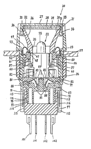
button switch, the structure shown in Figure 20 is
known. Specifically, in an inner space between a
switch cover 201 and a switch base 202, disposed
opposite one another in the vertical direction, an
upper terminal 203 and a lower terminal 204 are
arranged opposite one another. Between the terminals
is a predetermined ~ap. Contacts 205, 2n6 are
secured to the opposin~ faces of both of the
terminals 203, 204 respectively.
A common terminal 207 is disposed vertically on
one side of the contacts 205, 206. The base end of a
first movable member 208 is engaged in the lower
portion of the common terminal 207 while the free end
of the first movable member 208 is situated in the
vicinity of the contacts 205, 206 of the
above-mentioned upper and lower terminals 203, 204.
A second movable member 209 inserted between
the contacts 205, 206 is engaged at one end thereof
to the free end of the first movable member 208. The
second movable member 209 has contacts 210 secured at
positions corresponding to the contacts 205, 206
respectively. Further, a spring 211 is stretched
between the outer end of the second movable member
209 and the common terminal 207, so that the contact
1270~7~
-- 7
210 on the second movable member 209 is always biased
to be in contact with the contact 206 on the lower
terminal 204.
An operation member 212 subject to the
depressing operation is supported above the free end
of the second movable member 209~ When the operation
member 212 is depressed, the free end of the second
movable member 209 moves downwardly to switch the
contact 210 of the second movable member 209 from the
contact 206 on the lower terminal 204 to the contact
205 on the upper terminal 203.
Contact structures constructed as described
above have the following problems. Namely, upon
switching the second movable member 209, the second
movable member is slanted an amount corresponding to
the amount of depression of the operation member 212
resulting in a slip, due to the slanting between the
contact 210 of the second movable member 209 and the
contact 206 on the lower terminal 204 in a partially
contacted state. There is a similar slippage in the
contact between the contact 205 on the upper terminal
203 and the contact 210 of the second movable member
209 after the switching operation.
As a result of the slippin~ contact is acted
between these contacts 206, 210 and between the
contacts 205, 210, the contact faces are remarkably
abraded or roughened, thereby resulting in poor
contact, reduction in the switch operation
characteristic and, thus, reduction in the switch
life.
1'~70~7~
-- 8
As shown in Figures 1, 2 and 3, an illumination
type push button switch 20 comprises a push button
unit 21 for switching operation, an illumination unit
22 for illuminating the illumination face, a plunqer
23 for transmitting the depressing amount of the push
button unit 21 downwardly, a socket unit 24 for the
electrical connection of the illumination unit 22, a
switch unit 25 actuated by the depression of the
plunger 23, and a housing 26 for enclosing each of the
elements 21 - 25.
(a) Description of the Push Button Unit
The push button unit 21 is constructed as
described below.
Specifically, a rectangular box-like push button
27 optionally pigmented with red, yellow, green or
like other color and open at the bottom contains on
the inside thereof a rectangular mark plate 28 having
a mark for indicating the switching function and a
rectangular diffusion plate 29 for diffusing light. A
reflection member 30 is inserted fittingly
therebelow.
The diffusion plate 29 is recessed at the top
surface thereof and the mark plate 28 fits into the
recess.
The reflection member 30 has a rectangular
peripheral edge 31 formed at the upper end thereof
capable of fitting into the opening in the push button
27. A step 32 is formed on the inside of the
peripheral edge 31, to which diffusion plate 29 is
fitted at the lower surface thereof.
127V~76
g
Engagements 33, 33 are formed stepwise on
opposite sides of the outer surface of the peripheral
edge 31 oE the reflection member 30. Engaginq
protrusions 34, 34 are formed in the inner wall of the
bottom opening of the push button 27 and they
correspond to the engagements 33, 33, so that upon
fitting of the reflection member 30 to the opening,
the engagements 33, 33 and the engaging protrusions
3~, 34 are engaged with each other to secure together
the push button 27, the mark plate 28, the diffusion
plate 29 and the reflection member 30.
The circumferential surface of the reflection
member 30 narrows from the upper to the lower portions
as a square conical shape, in which the central
portion constitutes a cylindrical portion 35, the
inner peripheral surface constitutes a reflection
surface 36 slanted toward the central portion and the
reflection surface 36 reflects the light from the
illumination element contained in the cylindrical
portion 35 upwardly.
The cylindrical portion 35 of the reflection
member 30 is equipped with a structure for supporting
the illumination unit 22 and a structure for
regulating the direction of the illumination unit 22.
Specifically, supports 37, 37 are arranged at
opposing positions on the cylindrical portion 35 oE
the reflection member 30 and the supports 37, 37 have
elongate grooves 38, 38 each of a length corresponding
to the depressing stroke of the push button unit 21.
lX7087~
-- 10
The illumination unit 22 contained within the
opening of the cylindrical portion 35 has protrusions
40 formed at the side of an element holder 39
thereof, which protrusions fit into the elongate
grooves 38.
Further, protrusions 41, 41 acting on the
supports 37, 37 are arranged at the lower outer
periphery of the element holder 39.
The support 37 has a notch 42 formed at one
side edge thereof and an abutment 43 at the lower end
thereof, which act as described below.
As shown in Figure 4, the notch 42 allows the
protrusion 41 to be inserted therethrough when the
protrusion 40 of the element holder 39 is fitted in
the elongate groove 38 of the support 37 in the
direction of enhousing the illumination unit 22 used
as the illumination type push button switch 20.
Furtherl as shown in Figure 5, an abutment 43
abuts against the upper surface of the protrusion 41
of the element holder 39 and inhibits the insertion
of the protrusion 41 when the protrusion 40 of the
element holder 39 is enqaged in the elonqate qroove
38 of the support 37 in the direction of enhousinq
the illumination unit 22 used as a display device by
rotating the illumination unit 22 by 180.
1'~7(~7'~i
By the operation as described above, the
direction o~ enhousing the il1umination unit 22 is
regulated to a predetermined direction and, by
supporting the illumination unit 22 on the supports
37, 37, assembling work for the push button unit 21
and the illumination unit 22 is facilitated.
The cylindrical portion 35 of the reflection
member 30 is equipped with a structure for connectin~
the plunger 23.
specifically, engaging fingers 44, 44 are
arranged at opposing positions on the cylindrical
portion 35 and are displaced by 90 degrees from the
positions of the supports 37, 37. The engaging
fingers 44, 44 are formed with seizinq grooves 45, 45
open at the lower ends.
The plunger 23 is in a cylindrical shape and
has protrusions 46, 46 formed on an inner wall at the
upper end thereof at positions opposite to the
engaging fingers 44, 44. The protrusions 46, 46 are
engaged with and put in the seizing grooves 45, 45 in
the enga~ing fingers 44, 44 of the reflection member
when the reflection member 30 and the plunger 23 are
joined. In this manner the reflection member 30 and
the plunger 23 are connected.
Further, by the above-mentioned connection, the
depressing operation of the push button unit 21 is
transmitted to the plunger 23.
1270~7~
- 12
Between the cylindrical portion 35 of the
reflection member 30 and the inner wall surface of
the housing 26 is formed a seal structure.
Specifically, a step 47 is formed at the outer
circumferential edge of the cylindrical portion 35 of
the reflection member 30 and a step 48 formed at the
upper end edge of the plunger 23 corresponds to the
step 47. An annular engaging groove is formed by
joining both of the steps 47, 48.
The seal 49 is molded with resilient material
into a circular shape surrounding the periphery and
the inner end edge 50 of the seal 49 is thicker than
the engaging groove formed by the steps 47, 48. When
the steps 47, 48 are joined, the inner end edge 50 is
put therebetween. When the inner end edge 50 is
fitted into this engaging groove, it is seized and
held by the enqaging groove.
The outer end edge 51 of the seal 49 fits into
an annular groove 52 formed in the inner wall surface
of the housing 26. An annular fixing ring 53 is
fitted over the upper portion of the annular groove
52 to secure the outer end edge 51 to the annular
groove 52.
The seal 49 prevents external dust or the like
from entering the inside of the unit.
lX70~7~:;
- 13
The upper end of the housing 26 has a
rectangular box-like conEiguration so that the push
button uni~ 21 constituted as described above may be
fitted therein. The central portion has a
cylindrical shape so that the cylindrical plunger 23
may be mounted therein.
(b) Description of Illumination Unit
The illumination unit 22 comprises an
illumination element 54 and the element holder 39 as
described above. The illumination element 54
includes two possible types, that is, a lamp 55 and a
LED 56, which are respectively fitted to the element
holder 39. The type selected depends on the
particular use.
Lead terminals 57, 57 of the lamp 55 are in a
round bar shape and lead terminals 58, 58 of the LED
56 have a plate-like shape. The plate-like lead
terminals 58, 58 are formed somewhat thinner than the
round rod-like lead terminals 57, 57.
The illumination unit 22 is enclosed in and
engaged to the cylindrical portion 35 at the lower
end of the push button unit 21.
(c) Description of the Plunger
The plunger 23 is in a cylindrical
configuration and has at the upper end edge thereof a
diameter reduction step 59, which abuts against a
flange 60 formed at the upper end edge of the
cylindrical inner wall of the housing 26 thereby
1~70~7~
- 14
being prevented from slip-off when the plunger 23 is
inserted from the lower end opening of the housing
26.
Further, a returning spring 61 is housed in the
inside of the plunqer 23 and the spring 61
resiliently biases the plunger 23 upwardly by
abutting at the lower end thereof against the upper
surface oE the socket unit.
An operation member 62 and a control member 63
extend from the lower peripheral edge of the plunger
23. The operation member 62 is formed as a pair,
each located opposite to the switch operation portion
of the switch unit 25 to perform switching operation
upon depression of the plunger 23.
The control member 63 is formed with an
elongate groove 64 having a length corresponding to
the depressing stroke of the push button unit 21.
The elongate groove 64 is engaged with a protrusion
66 disposed on the side of the socket base 65 to
control the depression stroke of the plunger 23, as
well as control the circumferential rotation of the
plunger 23,
The inner circumferential wall .surface at the
upper end opening of the plunger 23 is provided with
a control structure for limiting the direction of
insertion of the illumination unit 22 to one
direction.
lX7(3~37
-- 15
As shown also in Figure 6, protrusions 67, 67
protrude Erom the inner circumferential wall surface
of the upper end opening of the plunger 23 to
thereby form grooves 68 between each of the
protrusions 67, 67.
The protrusions 67, 67 and the groove 68 allow
insertion of the protrusions 41, 41 of the
illumination unit 22. When the illumination unit 22
is inserted at 180 rotation, the protrusions 67, 67
are abutted against the protrusions 41, 41 to inhibit
the insertion of the illumination unit 22
therethrough.
Since the direction of inserting the
illumination unit 22 is controlled to a predetermined
direction by the above-mentioned regulation
structure, a~ erroneous insertion can be prevented,
for example, in a case of using the LED 56 having a
polarity as the illumination element 54.
An alternating mechanism 69 is formed between
the socket unit 24 of the plunger 23 and the socket
base 65 of the socket unit 24.
As shown in Figures 3 and 7, the alternating
mechanism 69 comprises an alternating cam 71 pivoted
on the shaft 70 at the outer wall surface from the
socket base 65, and a cam control portion 72 formed
in the wall surface of the plunger 23 opposite to the
cam 71.
The cam 71 is in a rectangular shape and has
engaging grooves 73, 73 formed on two opposing
shorter sides.
- 16
The cam control section 72 is defined by
forming a window 74 in the wall surface of the
plunger 23, in which four control sections 75, 75,
77, 78 are formed on the peripheral edge of the
window 74.
The first control section 75 is defined by
forming an arcuate corner on one upper side of the
window 74. When the cam 71 abuts aqainst the first
control section 75, the cam 71 i9 rotated in one
direction by a predetérmined angle.
The second control section 76 is defined by
forming a corner at a position somewhat higher than
that for the control section 75 at the other upper
ènd of the window 74, and it controls the rotating
position of the cam 71 rotated by a predetermined
amount by the above-mentioned first control section
75 by engaging with the engaging groove 73 situated
at the upper end of the cam 71.
The third control section 77 is defined by
forming a corner on one side of the middle portion of
the window 74, and it controls the position of the
plunger 23 at the switch operation position by
engaging the engaging groove 73 situated at the lower
end of the cam 71, the position of which is
controlled by the second control section 76.
The fourth control section 78 is defined by a
vertical face formed on one side of the lower portion
of the window 74, and it holds the rotating state of
the cam 71 which has been rotated by one-half upon
successive downward movement and the subsequent
returning of the plunger 23.
~7(~
- 17
The alternating mechanism 69 is operated as
shown in Figures a-h. Specifically, the plunger 23
is situated above and the switch is put to OFF in the
state shown in Figure (a).
When the plunger 23 is pushed down from this
position, the first control section 75 abuts against
one upper corner of the cam 71 to rotate the cam 71
clockwise as shown in Figure (b).
Further, when the plunger 23 is moved
downwardly, the second control section 76 engages
with the engaging groove 73 at the upper end of the
cam 71 to stop the rotation of the ca~ 71 and control
the position thereof as shown in Figure (c).
Then, when the plunger 23 is released, since
the plunger 23 is moved upwardly by the s~ring 61,
the third control section 77 abuts against one lower
corner of the cam 71 to sliqhtly rotate the cam 71
clockwise as shown in Figure (d).
Next, as shown in Figure (e), the third control
section 77 engages the engaging groove 73 at the
lower end to stop the upward movement of the plunger
23. That is, the plunger 23 is locked at that
position, where the switch is operating at ON and
locked at the ON state.
Then, in order to release the locked state as
described above, the plunger 23 is depressed again.
Upon this depressing operation, the plunyer 23 moves
downwardly somewhat.
As shown in Figure (f), since the second
control section 76 abuts against one corner of the
cam 71, the cam 71 is rotated clockwise to release
the locked state.
127()87~
- 18
As shown in Figure (g), the cam 71 is rotated
substantially to a horizontal state and, upon release
of the plunqer 23 in this state, the plunger 23 is
moved upwardly by the action of the spring 61.
In the initial stage of the upward movement, as
shown in Figure (h), the third control section 77
abuts against the side portion of the cam 71 to
further rotate the cam 71. When the plunger 23 moves
upwardly from this position, the side portion of the
cam 71 is in sliding contact with the fourth control
section 78, whereby the plunger 23 moves upwardly to
the upper limit position, that is, to the position
where the switch is OFF and is in the position shown
by Figure (a).
As described above, the alternating mechanism
69 can maintain the ON state of the switch by one
depressing operation of the push button unit 21 by
way of the plunger 23 and can bring the switch to the
OFF state by a further single depressing operation.
In the foregoing embodiment, although the cam
control portion 72 is defined by the wall surface of
the plun~er 23, the actuation member 62 of the
plunger 23 may be made broader in the lateral
direction and the cam control portion 72 may be
formed to the operation member 62 as another ~eans.
(d) Description of the Receptacle Unit
-
The socket unit 24 comprises the socket base 65
as already described and a socket cover 79 joined to
the upper surface of the socket base 65.
The socket cover 79 has an engaging structure
formed at the upper surface thereof for engaging the
element holder 39 for the illumination unit 22.
1~70~7ti
-- 19
Specifically, engaging fingers 80, 80 are
erected at the upper surface o~ the socket cover 79
at a predetermined distance from each other and the
engaging fingers 80, 80 respectively have seizing
grooves 81, 81 each opening at the upper ends
thereof.
Further, protrusions 82, 82 are formed on the
side of the element holder 39 of the illumination
unit 22 at positions opposite the engaging fin~ers
80, 80. The protrusions 82, 82 are engaged in and
put between the seizing grooves 81, 81 of the
engaging fingers 80, 80 when the illumination unit 22
is mounted to the upper surface of the socket cover
79. In this way the illumination unit 22 is
connected to the upper surface of the socket unit
24.
Further, insertion ports 83, 83 are formed in
the socket cover 79 so as to penetrate the cover 79.
The insertion ports 83, 83 are formed at positions
opposite to lead terminal 57 or 58 of the
illumination element 54 when the illumination unit 22
is mounted to the upper surface of the socket cover
79 and allow the lead terminal 57 or 58 to pass
therethrough~
Guide members 84, 84 are erected on the upper
surface of the socket cover 79 and they function to
guide the abutment of the returninq spring 61.
As shown in Figure 8 through Figure 11, socket
holes 85, 85 are formed in the upper surface of the
socket base 65 and they are formed at positions
corresponding to the insertion ports 83, 83 of the
socket cover 79. The socket holes 85, 85 have a
1'~7()~
- 20
lateral width that permits the insertion of the lead
terminal 58 of the LED 56. The holes 85, 85 are
formed with recesses 87, 87 at the hole walls 86, 86
respectively, and the recesses 87, 87 are formed
vertically and engaged to a portion of the
circumferential surface of the round rod type lead
terminals 57, 57 of the lamp 55.
Into the inside of the socket holes 85, 85
opposite to the hole walls 86, 86, are inserted the
free ends of the contact member 88, 88. The contact
members 88, 88 are bent at the middle portions
thereof so as to provide a resiliency, and are in
resilient contact with the respective lead terminals
57, 58.
The thickness is different between the lead
terminal of the lamp 55 and the lead terminals 58 of
the LED 56. By fitting a portion of the lead
terminal 57 of the lamp 55 to the recesses 87, 87,
the protruding amount of the lead terminal 57 is
substantially equal with the thickness of the lead
terminal 58 of the LED 56. Thus the resiliency of
the contact member 88 acts equally on both of the
lead terminals 57, 58.
While the recess 87 as shown is formed in the
hole wall 86, the recess 87 may also be formed on the
side of the contact member as an alternative.
As shown in Figure 12, ~rooves 89, 89 to be
connected with the socket holes 85, 85 are formed in
~71~7~,
- 21
the socket base 65 toward the outer circumference.
Engaging ports 90, 90 are formed at intermediate
positions between the grooves 89, 89.
The engaging ports 90, 90 are engaged by
engagements 92, 92 formed by bending the upper ends
of the connection terminals 91, 91. In this way the
connection terminals 91, 91 are prevented from
detachment even when there is a downward pulling
action acting on the connection terminals 91, 91.
To a flat portion at the upper ends of the
connection terminals 91, 91 are fixed the base ends
of the contact members 88, 88.
Further, joining members 93, 93 are formed at
positions on the peripheral edge of the socket cover
79 corresponding to the positions of the grooves 89,
89. when the joining members 93, 93 are placed in
the grooves 89, 89, the upper ends of the connection
terminals 91, 91 are covered to obtain satisfactory
insulation for the portion of the socket holes 85,
85. At the same time, the joining position between
the socket base 65 and the socket cover 79 is
controlled by the engagement between the grooves
89, 89 and the joining members 93, 93.
As shown also in Figure 13, a control portion 94
is formed at the lower surface of the socket base 65,
and the control portion 94 acts on the switch unit 25 to
~27V~7~
be described later. The specific operation will be
made clear in the later explanation for the switeh
unit 25.
Further, connection member 95, 95 extend down
from opposing positions along the circumferential
edge of the socket base 65. Engaging fingers 96, 96
are formed respectively at the outer side of the
lcwer ends of the connection members 95, 95. The
engaging fingers 96, 96 are used for connecting the
switch unit 25 as decribed later.
(e) Description of the Switch Unit
The switch unit 25 comprises a double-throwing
type switeh meehanism, in whieh two switch meehanisms
98, 98 are constituted on a plane, and the switch
meehanisms 98, 98 are aetuated by the paired operation
members 62, 62 of the plunger 23 respectively.
The switch mechanism 98 shown in Figure 14
denotes one set and the other set is constituted in a
similar manner.
The one set of the switch mechanism 98
eomprises a pair left and right of the first terminal
101 and second terminal 102 having secured stationary
eontaets 99, 100 opposed to each other one above the
other. They are disposed on the switch base 97 and
the respective lower ends of the terminals are
extended below the switch base 97.
1~70~76
- 23
A free end of a first movable member 103 is
inserted between the stationary contacts 99, lnO and
the free end has a width sufficient to bridge the
opposing faces of the stationary contacts 99, 99,
100, 100 situated at the left and right. Contacts
104 are secured to the upper and lower surfaces of
the broad portion for contact with each of the
contacts 99, 100.
An engaging protrusion 105 is disposed at the
central portion on the free end of the first movable
member, and the base end of the movable member is
engaged in a recess 107 formed on the lower portion
of the erect member 106 located on the switch base
97.
The engaging protrusion 105 of the first
movable member 103 is engaged with a hole 109 formed
at one end of a second movable member 108 and the
movable members 103, 108 are rotatably mounted.
The second movable member 108 has formed at one
end thereof an erect member 110 formed by bending to
erect a portion thereof. The erected member 110 is
disposed to the switch operation portion and it is
positioned to contact the lower end of the operation
member 62 of the plunger 23.
one end of a spring 111 is connected to the
erect member 110 of the second movable member 108,
and the other end of the spring 111 is engaged in the
recess 112 formed at the upper end of the erect
member 106. The spring 111 resiliently biases the
1~270~7~i
- 24
erect member 110 upwardly, and energi2es the contac-t
104 of the first movable member 103 to press against
the stationary contact 104 of the terminal I02 by way
of the second movable member 108.
In the state where the contact 104 is in
contact with the stationary contact 100 below, the
switch function is kept at an OFF state.
When the erect member 110 is depressed by the
operation member 62 of the plunger 23 from this
state, the dead point of the spring 111 is exceeded
due to the downward movement of the erect member 110,
whereby the second movable member 108 is reversed.
Due to the reversal, the contact 104 of the first
movable member 103 moves upwardly to be in contact
wtih the stationary contact 99 of the first terminal
101 above to attain the ON state of the switchin~
function.
As described above when the contact 104 and the
stationary contacts 99, 100 are in contact with or
are parted from each other, there are no lateral
slips between the contacts, thus preventing abrasion
between them. Further, the contacts are parted from
and are in contact with each other under a certain
pressure of the spring 111 to attain a stable
operation.
Post members 113, 113 are located at opposing
positions around the peripheral edge of the upper
surface of the switch base 97 and engaginq holes
~271~
- 25
114, 114 are formed in the inside of the base of the
post members 113, 113 respectively.
The engaging holes 114, 114 are engaged with
the engaging fingers 96, 96 of the connection members
S 95, 95 that extend down from the socket base 65 to
connect them with each other.
When the socket base 65 is connected to the
switch base 97 as described above, the upper surface
of the switch mechanism 98 is covered by the socket
base 65. The covered state is particularly effective
when assembling the switch. For instance, when the
switch mechanism 98 is assembled and contained within
the housing 26, each of the elements on the switch
mechanism 98 can be prevented from contacting the
opening edge of the housing 26 and disassembling.
Further, in the above-mentioned state, since
the control section 94 formed to the socket base 65
is in contact with the upper surface of the spring
which is left free to inhibit the swinging movement
of the spring 111, each of the elements of the switch
mechanism 98 can be prevented from dismantling due to
the swing of the spring 111 upon assembling.
The post members 113, 113 on the switch base 97
have grooves 115, 115 formed on the outer surface
thereof. The position of these grooves corresponds
to the position of the connection terminals 91, 91 of
the socket unit 24. The grooves are capable of
containing the connection terminals 91, 91.
70876
-- 26
In addition, gaps 116, 116 are formed between
the grooves 115, 115 and the connection terminals 91,
91. The gaps 116, 116 constitute effective
insulation when the push button switch 20 is mounted
to the switch socket as described later.
(f) Description of the Housing
The housing 26 as described above, has two
securing means for mounting it to a mounting panel
117.
As shown in Figures 15 and 16, one of the
securing means is a securing nut 118 and the other is
a securing resilient member 119.
The housing 26 described above has a
rectangular portion 120 formed at the upper end
thereof for housing the button unit 21 described
above, and a cylindrical portion 121 that is
centrally located at the bottom of the rectangular
portion 120.
On the inside of the cylindrical portion 121
are located the illumination unit 22, plunger 23,
receptacle unit 24 and switch unit 25 described
previously.
Engaging holes 122, 122 are formed at opposite
sides on the lower end of the housing 26, and the
engaging holes 122, 122 are engaged with engaging
fingers 123, 123 formed at the side of the switch
base 97. In this way the switch unit 25 is secured
to the housing 26.
~270~7~i
- 27
The lower surface of the rectangular portion
120 is an engaging portion 124. Threads 125 are
formed around the outer circumferential surface on an
upper portion of the cylindrical portion 121 and are
for threading engagement with the nut 118. By
inserting the cylindrical portion 121 through the
opening 126 of a mounting panel 117 and
screw-coupling the nut 118, the housing 26 can be
mounted to the mounting panel 117. The mounting
panel 117 is placed between the engaging portion 124
and the nut 118.
Engaging holes 127, 127 are formed on opposite
sides of the threaded portion 125 of the cylindrical
portion 121 and the resilient member 119 as described
above is engaged to the engaging holes 127, 127.
The resilient member 119 is formed with a
resilient leaf spring material and comprises a
band-like portion 128 formed in an annular shape and
a plurality of engaging members 129 that extend
upwardly from the band-like portion 128. The
band-like portion 128 is split at one side so that
the annular member can be extended. Lugs 130, 130
are formed at the joint in the band-like portion 128,
and a lug 131 is formed on the inside at a position
on the band-like portion 128 opposite to the lugs
130.
7~87~;
- 28
The lugs 130, 131 as described above engage in
the engaging holes 127, 127 of the cylindrical
portion 121 respectively by extending the band-like
portion 128.
The engaging members 129 are bent at the upper
ends thereof so as to turn outwardly and the bent
portion creates outward biasing force.
As described above, when the housing 26 mounted
with the resilient member 119 on the cylindrical
portion 121 is inserted into the opening 126 of the
mounting panel 117 until the panel abuts against the
engaging portion 124, the housing is secured by the
engaging members 129 of the resilient member 119 that
urges the opening 126 outwardly.
As described above, the mounting of the housing
26 includes two modes, that is, by means of the nut
118 and the resilient member 119, which can be used
selectively.
(g) Description of the Switch Receptacle
The illumination type push button switch 20
having thus been constituted is mounted to a switch
socket 132 to be described below.
The switch socket 132 has a cylindrical shape,
in which socket holes 133 are formed at positions on
the upper plane corresponding to the first and second
terminals 101, 102 of the switch unit 25. Contact
1270876
- 29
members 134 are contained in the socket holes 133
with the contact members 134 beinq electrically
connected respectively with the terminals 101, 102.
Further, protrusions 135, 135 are provided on
the switch receptacle 132 at positions corresponding
to the connection terminals 91, 91 of the socket unit
24. The protrusions 135, 135 are inserted in the
grooves 115, 115 formed in the post members 113, 113
of the switch base 97 and inserted in the gaps 116,
116 between the grooves 115, 115 and the connection
terminals 91, 91.
Then, socket holes 136, 136 are formed on the
outer side of the protrusions 135, 135 and contact
members 137, 137 are contained within the socket
holes 136, 136. The contact members 137, 137 are
electrically connected ith the connection terminals
91, 91.
In the switch socket 132 thus constructed, the
creeping distance between the connection terminals
91, 91 and other terminals 101, 102 is increased to
improve the insulation performance. Accordingly, the
protrusions 135, 135 are inserted between the
connection terminals 91, 91 and other terminals 101,
102, when the illumination type push button switch 20
is mounted.
lZ7(~37~i
- 30
In the illumination type push button switch 20
and the switch socket 132 described above,
improvements have been obtained in switch operation
characteristics, workability in the assembling of
each of the elements and, the insulation performance.
However, this invention is no way limited only to
the structure of the described preferred embodiment
but it may be made with modifications based on the
spirit of this invention.