Note: Descriptions are shown in the official language in which they were submitted.
METHODS AND APPARATUS FOR INVESTIGATING _USCLES
_D/OR JOINTS
Field of the Invention
This invention relates to methods of and appa-
ratus for investigating or examining muscles and/or
joints.
1 0
Various electrical/electronic devices are known
which purport to be able to indicate the condition or
tone of muscles. However, these known devices have
various disadvantages and are not really designed to
produce the information which would be of greatest
value. Chiropractors and other persons who are used to
manipulating the body are able to determine by feel both
the condition and tone of muscles as well as any assoc-
iated play or yield in a join~, but this is a subjective
impression. It is by explolting these mechanical
impedance properties of muscles and joints that the
present invention differs fron previous devices and
achieves its advantages.
In order to be able to carry out analysis or
treatment it is advantageous to be able to determine
variations in muscle tone and joint play both on a local
level and on a gross scale. It is an object of the
invention to provide a method of and apparatus for
achieving this.
It is a further object of the present invention
? -. t .~
`" ` ` : :- .
:
: '
~ 3~
1to provide methods of and apparatus for inventigating
muscles and/or joints whereby the operator can produce a
physica] record or display indicative of muscle condi-
tion and joint playor yield.
5The skilled chiropractor will also be able to
recognise patterns of muscle tone and joint play. With
the method and apparatus of the present invention one
can produce a record or display illustrative of muscle
tone and/or joint play over a small or large area of the
10patient by taking appropriate readings at a multiplicity
of sites.
It is yet a further object of the present in-
vention to provide such a method or apparatus whereby a
test procedure carried out on a patient can be compared
15with previous investigations on the same patient so that
a record of progress or deterioration can be achieved.
It is another object of the present invention to
provide a method and apparatus suitable for carrying out
the procedures mentioned above, in which a sensing "gun"
20is used which preferably operates on mechanical or
electro-mechanical principles and which can be linked up
to electrical and/or electronic recording and/or meas-
uring and/or display means.
In accordance with the present invention there
25is provided apparatus for investigating muscles and/or
joints, comprising a pulse-generating device to be
positioned in contact with a body under investigation to
apply a force pulse or pulses to the body, first sensing
means providing a first output representative of the
30reaction of the body to the force o~ the applied pulse
or pulses, second sensing means providing a second
output representative of the acceleration of the body
resulting from the applied pulse or pulses, and pro-
cessing means arranged to use said ~irst and second
35outputs to provide a third output which is based upon a
. ,
.
.
- : . - . :.
:
~7(3~3~3~
1 combination of the information in both first and second
outputs and which is representative o~ muscle tone
and/or joint yield.
Preferably, the first sensing means cornprises a
~orce transducer providing an electrical waveforrn
output, and the second sensing means comprises an accel-
erometer providing an electrical waveform out~ut.
Preferably, the pulse-generating device produces
a pulse ha~ing a slowly rising leading edge~
In a preferred embodiment, the processing means
comprises computer means arranged to divide one of said
first and second outputs by the other, thereby to
produce said third output.
Brief description of the drawinqs
In order that the invention may be more fully
understood, a number of embodiments of apparatus in
accordance with the invention will now be described by
way of example and with reference to the accompanying
drawings, in which:
Fig. 1 is a block schematic diagram of a first
embodiment of apparatus in accordance with theinvention;
Fig. 2 is h schematic illustrationof an alter-
native system for generating the force pulses;
Fig. 3 is a schematic diagram of a furthersystem for generating the force pulses;
Fig. 4 is a schematic diayram illustrating an
alternative embodiment in which the transducers are
separated;
Fig. 5 is a waveform diagram showing typical
force and acceleration waveforms when the apparatus of
the present invention is used on soft tissue; and,
Fig. 6 is an equivalent waveform diagram showing
typical force and acceleration waveforms when the
..
,.. ~ . ~.
,
~7(3~
1 apparatus of the present invention is used on hard
muscle or joints.
Description of the preferred embodiments
--_
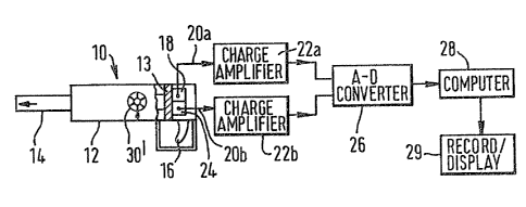
~eferring first to Fig. 1, the apparatus is
shown as comprising a sensing "gun" or probe which is
indicated generally at 10. The sensing gun shown in the
drawing is designed to be hand-held during use. The gun
comprises a body portion 12 which serves as a housing
for a spring-loaded piston 13 attached to a piston rod
14 which functions as a plunger. The piston/piston rod
assembly is provided with latch means within the housing
12 so that the piston and piston rod can be "cocked" for
subsequent release by the actuation of a trigger mech-
anism 16. In response to actuation of the trigger
mechanism 16 the plunger 14 is displaced axially out-
wardly of the housing 12 with a stroke which is pre-
ferably of the order of ~ inch (6mm).
The force pulse which is generated by the act-
uation of the plunger 14 should advantageously have a
slowly rising pulse waveform, and is preferably part of
a sinusoidal waveform. The force pulse generated by the
plunger 14 preferably has a duration of about 0.2 sec-
onds and a peak amplitude values of the order of
Newton. However, these figures are to be considered as
examples only and the force pulse parameters may vary
from the figures given and may indeed be selected in
dependence upon the particular patient or upon the
particular tissues or joints to be examined. In carrying
out the investigation in accordance with the invention
one is seeking to determine the compliance of tissue and
the yield of joints. A force pulse with a slowly rising
leading edge is considered to be most advantageous for
this purpose. Additionally, the force pulse amplitude
-: . .,
~ 3~
1 should not be too great, otherwise one creates such dis-
tortion within the body that rnuscle mobility and joint
yield cannot readily be determined.
A~jacent to the end of the yun rernote from the
end of the plunger 14 which contacts the patient, there
is provided a force transducer 18 which measures the
force exerted by the plunger against the body as the
plunger moves forward. Thls of course is representative
of the reaction force exerted by the body on the end of
the plunger. The force transducer 18 may comprise a
load cell, a strain guage, or other transducer mechanism
appropriate to measure forces of the magnitude involved
here. For example, the transducer 18 may be a mini-
ature quartz force transducer suitable for measuring
dynamic and quasistatic forces. The force to be re-
corded acts on the quartz element within the transducer.
~` On the occurrence of the force pulse, the longitudinal
piezoelectric effect which is produced causes an elec-
trostatic charge to be generated in the quartz element.
The transducer 18 is connected by an output lead 20a to
a charge amplifier 22a. The output signals from the
force transducer 18 are transformed into proportional
output voltages in the charge amplifier 22a.
Also mounted at the end of the sensing gun
remote from the body-contact end of the plunger 14 is an
accelerometer 24. The accelerometer 24 is preferably a
miniature konic accelerometer, although other forms of
accelerometer could be used as alternatives. An accel-
erometer having a low resonant frequency is preferred.
With force pulses having parameters of the order of
magnitude referred to above, accelerations of the order
of 1 g will be generated. The accelerometer 24 is
- connected by an output cable 20b to a second charge
amplifier 22b where the output signal from the accel-
erometer is similarly transformed into a proportional
output vo,ltage.
` ,.
,;~ ~ ..
.
~`
.,
. .
~ - - . :~
f~i7~3~3~
1 The Olltputs of the cha~ge amplifiers ~2a and 22b
are fed to an analogue-to-digital converter 26, th~
digital output of which is fed to a computer 2~. The
computer 2B can incorporate or be connected to any
appropriate measuriny/recording/display apparatus or
instruments 29.
The sensing gun or probe 10 is preferably pro-
vided with a depth control adjustment mechanism, in-
dicated schematically at 30' in Fig. 1, whereby the
axial stroke of the piston rod 14 can be adjusted.
Various alternatives to the particular sensing
gun described above may be used. For example, the force
transducer 18 and accelerometer 24 may alternatively be
positioned on the plunger 14 itself, externally of the
housing, instead of at the trigger end of the gun. The
body-contact end of the plunger 14 may be provided, if
appropriate, with a resilient end cap, for example of
rubber~ The accelerometer 24 may be replaced by any
equivalent device which will satisfactorily measure the
acceleration and damping waveforms generated by the
reaction of the muscle and/or joint to the imposed force
pulse. An optical detector mechanism could for example
be used. It should be understood that the reference
herein to "acceleration" includes also deceleration, as
occurs when damping takes place.
Although the sensing gun shown in Fig. 1 is
designed to be hand-held against the patient undergoing
examination, one can alternatively arrange for the gun
to be fixed or clamped in position so that one avoids
any errors arising from movement of the operator. If
the gun is to be a hand-held instrument then it should
be heavy in order to increase its inertia.
Fig. 2 showsan alternative to the trigyer mech-
anism 16 for generating the force pulses. Here, a cam
30 is controlled as to its rotation by a spring 32. The
- .
. ', :', ~
,
~7~3~3~3
1 cam 30 is mounted on a central shaft 34. A cam follower
~6 in the form of a tappet is positioned so that it is
struck by the cam 30 in its rotational ~ovement.
Rotation of the cam follower 36 initiates a linear dis-
placernent of the plunger l4. The force pulse waveformcan thus be chosen by suitable choice of the cam profile
and of the force of the spring 32 which determines the
speed of rotation of the cam. If the cam 30 is detach-
able, one can select any one of a plurality of cams. A
1~ double-acting cam can be used to cancel out kickback of
the plunger. By providing the individual cams with
different profiles one can select the force pulse
shapes, depending upon the condition of the patient and
the nature of the tissues and/or joints to be investi-
gated.
Fig. 3 shows yet another method of generatingthe necessary force pulse. As shown in Fig. 3, the
plunger 14 is displaced by the action of a solenoid
mechanism 38 which is driven by an output waveform from
a waveform generator 40. The waveform generator 40 may
be triggered to produce an output initiating pulse by
operation of a push-button 42.
Fig. 4 is a diagrammatic representation of an
alternative embodiment, in which the accelerometer 24 is
not mounted on the gun 10 but is separate from it.
With this arrangement the force transducer 18 which is
still coupled to the plunger 14 remains as part o~ the
sensing gun, but the accelerometer 24 is in the Eorm oE
a separate unit which can be positioned as appropriate
on the skin o~ the patient. When the plunger is actu-
ated, the force pulse is transmitted through the tissue
and/or joint and the damping wave is picked up by the
accelerometer 24. The arrangement can be such that the
plunger 14 and accelerometer 24 are physically linked so
.. .
.
`
~ V~7~3~
--8--
1 that the two are moved over the patient ~s one, i.e. the
plunger 14 and accelerometer 24 are maintained a con-
stant distance apart, or alternatively the accelerolrleter
24 can be in the form oL a rovin~ probe which the
operator can position as he wishes.
In use, the sensing gun or probe 10 is placed
against a muscle and/or joint to be exarnined. This is
so whether the gun is hand-held or is clamped in a fixed
position. The firing of the gun will cause the piston
rod 14 to move axially relative to the housing and thus
to impart a single shock pulse to the patient. The use
of just single pulses is preferred. As mentioned above,
this force pulse preferably has a slowly rising leading
edge and is preferably substantially sinusoidal in
shape. Because the plunger 14 is in contact with the
body surface, the body will react to the pulse. The
force transducer 18 will measure the force imposed on
the body and its output on lead 20a will represent the
force pulse waveform, as shown at 50a and 50b in Fiys. 5
and 6. After the force pulse is generated one is
looking for information from the reaction of the body
which will enable one to determine the answers to two
questions. The ~irst question is whether the muscle
and/or joint moves easily, and the second question is
how hard does the muscle and/or joint try to stop moving
after it has begun to move in response to the force
pulse. These two parameters may be thought of as
mobility and damping. The reaction of the body to the
force pulse is determined by the accelerometer 24,
whether this is monitoring the movement of the plunger
14 directly or is sensing movement of the body at a
distance from the gun, as in the system shown in Fig. 4.
The output of the accelerometer 24 on lead 20b will
thus be an acceleratlon or damping waveform, for example
of the type shown at 52a and 52b in Figs. S and 6.
- ~
,. ... .
~; :
~., - ,
- :~` ' ' ` .' '':
~ 7 ~3~
1 It should be appreciated that the generation of
a "standar~" force pulse wil result in differ~nt shape~
of "force" waveform 50, dependiny upon the mobility of
the patient at the site which is being investigated.
The reaction of the body modifies the basic force pulse
and is what is measured by the force transducer 18; this
reaction can thus be thought of as a mobility wave.
Fig. 5 illustrates typical waveforms when a force pulse
isapplied to soft tissue, whereas Fig. 6 shows t'ne equi-
1 n valent typical waveforms when the same pulse is appliedto "hard" material, such a a joint or a hard muscle. It
will be seen from a comparison of Figs. 5 and 6 tha~ in
the case of the hard material the mobility wave 50b
falls away from its peak more sharply.
As will be seen from Figs. 5 and 6, the accel-
eration or damping wave 52a, 52b is of substantially
different form when one is considering soft tissue as
compared with harder material. As will be seen from
Fig. 5, in the case of soft tissue, there is an initial
accelexation of the tissue in the direction away from
the plunger 14, followed by an acceleration in the
opposite direction, back towards the plunger. In the
case of harder material, as shown in Fig. 6, there is
little or no initial acceleration in the direction away
from the plunger, and the first indication is an accel-
eration of the material in the direction back towards
the plunger. It is emphasised that the waveforms shown
in Figs. 5 and 6 are by way of example only and that the
actual waveforms in any particular case will vary,
dependiny upon the shape of the generated force pulse,
and the nature of the material to which the force pulse
is applied.
With the generation o~ a force pulse having a
duration of the order of 0.2 seconds, it is desirable to
record the mobility waveform SOa, 50b and damping
.. , ~
: . ,:
, ~
~7~3~ 3
,, 1 ()--
1 waveform 52a, 52b over a period o about 0.5 seconds
from the triggering of the force pulse. That sort of
period will be adequate to enable the essential inform-
ation contained in those waveforrns to be picked up.
In order to he able to provide the oper~tor with
the desired information as to the conditior, of the
muscles and/or joints, it is necessary to process the
information contained in the mobility and damping waves
50, 52 within the cornputer 28. The characteristics of
the two output waveforms contain information which can
be used objectively to determine muscle tone and/or
joint play. An important feature of the present inven-
tion lies in using the computer 28 to produce an output
which is based upon the interaction or interrelationship
of the two output waveforms 50 and 52. Analysis of the
mobility waveform will give the operator a certain
degree of information, and analysis of the damping
waveform would also give the operator certain infor-
mation. However, in accordance with the present inven-
~0 tion, it is use of these two waveforms jointly which
enables the operator to gain more definitive information
about the condition of the muscle or joint being invest-
igated. By the use of appropriate programmes in the
computer 28, together with an appropriate data base, a
comparison is made of two waveforms 50 and 52 and an
output is produced which is representative of that
comparison. Although the way in which the comparison of
the two waveforms is carried out can be varied, accord-
ing to particular circumstances and conditions, it is
considered that divislon of the instantaneous values of
one waveform by the instantaneous values of the other
waveform will prov;ide a meaningful output which is more
informative than what can be gained from a study of
either waveform alone. Division of one waveform by the
other will produce an output waveform with a shape whose
,, .~
: '
~ 3Y~3~
1 characteristics can be used hy the skilled opera~or to
determine muscle tone and joint play. The computer 28
can also be used to make cornparisons between such
resultant waveforms and predetermined "standard" wave-
forms. By means of the apparatus of the present inven--
tion one can produce an output, either graphically, or
numerically, or as a display or in some other way which
will not only tell the operator the condition of a
muscle or joint in relation to a predetermined standard
but which can also be used for comparison purposes, for
example by rnonitoring a patient's muscles or joints on a
regular basis and comparing the results to indicate the
improvement or deterioration in the muscles or joints.
It should be emphasised that althouyh division
of the one waveform by the other in the computer 28 is
one method of obtaining useful information as to the
muscles and joints, the present invention also includes
other ways of processing the information from those two
waveforms in order to produce a single output which is
based upon infor~ation from both waveforms.
The use of a single force pulse for application
to the patient is generally preferred. ~owever, a
multiple shock pulse method may be used if appropriate
Also, there may be advantages sometimes in using a
steady state system with sinusoidal excitation, instead
of a single shock, and in such a situation carrying out
frequency analysis of the response.
The apparatus and method of the present inven-
tion can be used not only on humans but also on animals.
. . .
.: : :
.: . ,