Note: Descriptions are shown in the official language in which they were submitted.
2 BACKGROUND OF THE: IN~JENTION
3 The present invention relates to devices which are useful in
4 the operation and con~rol of systems that regulate fluid flow.
More particularly the present invention pertains to a detector
6 which can sense fluid pressure in a line through which fluid is
7 being pumped. The present invention is particularly, but not
8 exclusively, useful in the health care field for indicating when
9 the intravenous administration of medical solutions to patients
has become impaired by an occlusion in the IV line.
` 11
12 DESCRIPTION OF THE PRIOR ART
13 Intravenous (IV) infusion therapy is a widely accepted
14 proceaure for many medical complications. ~s is to be expected,
such therapy frequently involves infusing highly potent'
16 medications to a patient. While this fact alone is sufficient to
17 require a precisely controlled procedure, the actual concern is
18 much broader in scope. Even when relatively harmless solutions
19 are being in~used, the procedure must still be dependably
accomplished with care and accuracy. Accordingly, the systems
21 used for IV therapy must include precision instruments which are
22 both durable and reliable.
23 In IV thecapy, the dosage and efficacy of the medical
24 solutions infused to the patient are important considerations.
They are not, however, the only considerations. Aside from the
26 phaemacological properties of the drugs being in~u~ed, the
-2-
l mechanical characteristics ~nd capabilities o~ the IV
2 administration device can be o great concern. Speci~ically, the
3 particular concern of the present inven~ion is or those problems
which are directly related to an undesirable bui~d up o fluid
pressure in the system. Such problems are well known.
6 Accordingly, there is a recognized need for an IV administration
7 device which dependably infuses medical solutions at safe
8 pressures that will not traumatize the patient or uncontrollably
9 infuse ~he pa~ient with a potentially harmful bolus of a high
potency drug. As will be appreciated, both of these unwanted
effects can result in an occlusion or blockage of the line that
12 causes a build up of fluid pressure.
13 The occlusion or blockage can be causea in any number of
14 ways. For instance, an IV line occlusion can be caused by the
inadvertent failure to release a clamp on the line or by a
16 crimping of the line such as when the patient rolls over the
17 line. On the other hand, the occlusion might be caused by
1~ improper needle placement such as wouid be caused if the needle
19 is inserted into a muscle rather ~han into a vein. Regardless of
the ause, either a build up of high fluid pressure or the sudden
21 release of high fluid pressure can be potentially harmful to the
22 patient. Thus, it is important that the IV administration device
23 be shut down whenever an occlusion or blockage in the line
24 prevents proper infusion of solutions to the patient.
2S Several devices have been disclosed which are intended to
26 help solve these problems by providing a warning whenever high
-3-
: ~ : '``
,
. ;
,:
~7~
l fluid pressures are encountered in the IV fluid line. For
2 example, U.S. Patent No. 4,373,5Z5 to Kobayashi discloses a
3 device for this purpose which correlates fluid pres$ure to
4 dimensional variations in the outer diameter for the tubing used
S for the IV line. Another example is U~S. Patent ~o. 4,244,365 to
6 McGill et al. which discloses a device that monitors or
7 excessive pressure in the set by using an optical sensor to
8 detect the ~luid level in a closed pressure chamber. Also, U.S.
9 Patent No. 4,277,227 to Jenkins discloses a device having a
resilient diaphragm disposed in the fluid line whose movement is
11 measured as an indication of fluid pressure in the line.
12 Significantly, the aforementioned devices were all designed with
13 the unique problems of IV therapy in mind. They all, however,
14 employ pressure sensing members which are structueally
independent of the actual pumping mechanism. This is somewhat
16 understandable when considering that IV administration sets must
17 deal with relatively low fluid pressutes and very small fluid
18 pressure differentials. With this in mind, a logical point for
19 taking such measurements is directly from the IV fluid line~
Such a connection, however, may not be as dieect as first
21 assumed. In each of the above-cited references some additional
22 member or device is incorporated into the system which can
23 introduce unwanted errors into the pressure reading.
24 An alternative to connecting the pressure sensing device
with the IV fluid line is to connect the device directly to the
26 pumping mechanism. I~ posi~ioned on the pumping mechanism in
-4-
" -: ,. :
:.
: . , .
: .
1 direct opposition to the ~luid~s resistive force, a pressure
2 sensing device is able to detect the actual force required to
3 pump fluid through the system. This force is, of course,
4 directly proportional to the fluid pressure in the system since
s the fluid pressure manifests itself as the resistive force
6 counteracting the pumping force~ ~he present invention
7 recognizes that an arrangement which takes advantage o this fact
8 can be applied in an IV administration system~ Although the
9 invention disclosed in U.S. Patent No. 4,286,925 to Standish
provides for a load transducer connected to the polished rod of a
11 well pump, Standish does not teach or suggest an apparatus that
12 is appropriate for use in IV therapy. Indeed, to contrast the
13 Standish apparatus with the present invention, it can be
1~ appreciated that the environments are quite different and that
the forces involved are of incomparable orders of magnitude.
16 In light of the above, it is recognized there is a need for
17 a fluid pressure detector having enhanced accuracy which can he
18 easily incorporated into an IV administration system. Further,
19 there is a need for an uncomplicated fluid pressure detector
which is reliable and durable.
21 Accordingly, it is an objec~ of the present invention to
22 pro~ide a fluid pressure detector for use in IV therapy which
23 will accurately deteemine when an occlusion has occurred in the
24 fluid line. Another object o the present innvention is to
2s provide an occlusion detector which is associated dieectly with
26 the pomping mechanism oE an IV in~usion pump. Still another
-5-
. "
~, . .. .
, . . .
1 object of the present invention is to provide an occlusion
2 detector which is sensitive to small variations in fluid pressure
3 at relatively low fluid pressure levels. Yet another object of
4 the present invention is to provide an IV line occlusion detector
s which is reliable and durable. It is yet another object of the
6 present invention to provide a 1uid pressure sensor which can be
7 easily manufactured and which is cost effective.
9 SUMI!SARY OF THE IMVENTIO~
The preerred embodiment o the novel IV fluid line
Il occlusion detector o~ the presen~ invention comprises a plunger
12 disposed for movement wi~hin the pumping chamber of an IV
13 infusion pump. The detector also comprises a motor driven
14 carriage. Connected be~ween the plungec and carriage is a
flexible beam havin~ i~s longitudinal axis generally aligned
l6 perpendicular to the direction of travel for the plunger. A
17 strain gauge is mounted on the beam to measure its flexural
18 deflections. Since the plunger is in direct contact with the
Iq fluid being pumped through the system, the flexural deflections
measured by the strain gauge are indicative of the ~luid pressure
21 in the IV line. The detector o~ the present invention also
22 comprises an alarm which is connected with the strain gauge to
23 alarm and stop the operation of the IV pump whenever beam
24 de~lections indicate a fluid pressure which evidences an
occlusion of the line.
26
~6-
:,
` , .' ' '' ' :~ `~'' `
~2~ 2~
l The novel features o~ this invention as well as the
2 invention itself, both as to its organization and operation, will
3 be best understood from the accompanying drawings taken in
4 conjunction with the accompanying description in which similar
S reference characters refer to similar parts and in which:
7 BRIEF DESCRIPTION OF THE DRAWINGS
8 Figure l is perspective view of a volumetric IV pump
9 employing th~ occlusion detector of the present invention;
Figure 2 is a ~ront elevational view of the occlusion
11 de~ector shown in operative engagement with the p~mping chamber
12 of a volumetric IV pump with portions shown in cross-section or
13 clarity;
14 ~Figure 3 is a front elevational view of the occlusion
detector connected with the drive shuttle of a volumetric IV
16 pump;
17 Figure 4 is a side view of the occlusion detector seen in
18 Figure 3;
19 Figure 5 is a side view of an alternative embodiment of an
occlusion detector;
Figure 6 is a side elevational view o~ the occlusion
22 detector shown in combination with a lead screw driven syringe
~3 pump, with portions broken away for clarity;
24 Figure 7 is a cross-sectional view o the occlusion detector
as seen along the line 7-7 in Figure 6; and
26
-7-
:~
'` ~ ~ , '' ,' , ~. '
:
,,~ - ,
~7~9Z~
1 Figure 8 is a cross~sectional view o~ an altecn~t~
2 embodiment o~ the occlusion detector as seen along the line 7-7
3 in Figure 6.
BRIEF DESCRIPTION OF T~E P~EFERRED EMBODIMENT
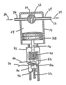
6 Referring initially to Figure 1, an IV volumetric pump
7 generally designated 10 is shown in operative association with a
8 fluid line 12. As is well known by those skilled in the art, an
9 IV pump 10 can be used for pumping fluids through a fluid line 12
for the purpose of infusing medical solutions to a patient.
Il Typically, an IV pump 10 of this type incorporates a.pumping
12 chamber 14 which is operatively engaged with a piston 16. A
13 drive shuttle 42 is mounted for reciprocal movement on IV pump 10
14 and is clampingly engaged with piston 16. 'rhe operation of an IV
pump incorporating structures similar to that envisioned for the
16 pumping mechanism of IV pump 10 as disclosed in U.S. Patent No.
17 3,985,133 which is assigned to the assignee of the present
18 invention~
19 The occlusion detector generally designated 20 in Figure 1
is assoc;ated with an actuator 22 such that reciprocal movement
21 of the actuator 22 is transferred ~through the mechanical
22 structure of occlusion detector 20 for movement Oe drive shuttle
23 42. As will be appreciated, the connection o~ drive shuttle 42
~ with the piston 16 causes the pumping action of piston 16 within
`:~ ` 2s ~luid chamber 14 for operation of the IV pump 10.
26
'` ~....
: -8-
. . ~ .;
-~ ; : :, . . ,, ;:
: :
, .:: . :. ";. - . . .:
: . .... ~ ~ ~ -
: ~ - ., . ~ ~, - . . , - .. .
: . . . . , .:. .
:
~L2~ 2a~
I A clearer understanding of the mechanism foe pumping medical
2 solutions through the IV pump 10 is obtained by reerence to
3 Figure 2. As seen in Figure 2, pumping chamber 14 is established
4 with an interior 24 for receiving fluids therein. Pumping
s chamber 14 is also provided with an inlet 26 which connectable in
6 fluid communication with the 1uid line 12. Additionally,
7 pumping chamber 14 is formed with an outlet 28 which is adap~ed
8 for connection into fluid communication with fluid line 12.
9 As seen in Figure 2, I~ pump 10 incorporates a valve 30
lo which is formed with an L-shaped groove 32. Through a mechanism
l (not shown), such as the one disclosed in U.S. Patent No.
12 3,985,133, IV pump 10 coordinates the rotation of valve 30 to
l3 alternately provide fluid communication between either inlet 26
l4 or outlet 28 and interior 24. As shown in Figure 2 any
lS advancement of piston 16 that moves the plunger 38 into the
16 interior 24 o~ pumping chamber 14 will cause fluid within
l? interior 24 to be expelled through groove 32 and autlet 28 and in
18 the direction of arrow 34 into 1uid line 12. As mentioned
l9 above, valve 30 is mounted in IV pump 10 for ro~ational movement
between its position as shown in Figure ~ and a position wherein
21 the ~-shape groove 32 establishes ~luid communcation between
æ inlet 26 and interior 24. When L-shaped groove 32 is established
23 in this latter described orientation a withdrawal of plunger 38
24 from the interior 24 causes fluid from a source (not shown) to
move in the directlon of arrow 36 through ~nlet 26 and into
26 interior 24.
_g_
,.
.... .: .
~ i .
.
~7~
1 As will be appreciated by the skilled artesan, the actual
2 pumping operation of IV pump 10 is accomplished by coordinating
3 the reciprocal movement of plunger 38 with the rotational
4 position of valve 30. Again, more precise description of such an
operation is found in U.S. Patent ~7O. 3,985,133.
6 Referring now to Figure 3~ i~ can be seen tha~ IV pump 10
7 incorporates a shuttle 42 which is slidingly mounted on a pair of
8 guide rails 44a and 44b. Guide rails 44a and 44b are aligned in
9 a substantially parallel manner to es~ablish a linear reciprocal
movement of shuttle 42. Shuttle 42 also is formed with abutment
Il 46 from which shuttle nose 48 extends. Shuttle nose 48 is ~ormed
12 with a detent 50 which is engageable with a coupler 40. As seen
13 in Figures 1 or 2, coupler 40 is formed as an extension o~ piston
14 16. It will be appreciated that upon engagement of coupler 40
with shuttle 42, the linear reciprocal motion of shuttle 42 i5
16 transmitted as a linear reciprocal motion to pis~on 16 and
17 plunger 38 for a purpose as previously described in the pumping
l8 operation o IV pump 10. A bracket S2 is fixedly attached to
19 shuttle 42 by any manner well known in the art, such a by use of
a bolt 54. As seen in Figure 3, a beam 56 is fixedly attached to
bracket 5~ in any manner well known in the art such as by bolt
22 S8~ A support 60 is fixedly attached ~o the beam 56 at the end
23 of beam 56 which is opposite rom its point of attachment to the
24 bracket 52. The engagement o carriage 60 with beam S6 can be
accomplished by any means, such as by bolt 6~.
26
-10-
:.:
'
~.27Q9;~9~
1 As best shown in Figure 3, it can be appreciated that, beam
2 56 is positioned in a manner which place6 the longitudinal ~xis
3 of beam 56 in a substantially perpendicular oLientation with
4 respect to direction o~ travel ~or shuttle 42. As also seen in
Figure 3, a strain gauge 64 is attached to the upper surface
6 56. Further, wiring 66 is used to make an electrical connection
7 between strain gauge 64 and an alarm means (not shown) which
8 incorporates electronic circuitry well known in the pertinent
9 art. The particular strain gauge for use in the present
invention can be of any type well known in the art which will
11 determine or react ~o fluctures of the beam 56.
12 ` It will also be noticed in Figure 3 tha~ a strain gauge 68
13 is attached to the under surface o beam 56. Again, the strain
14 ~au~ 68 is connected with wiring 70 which may also be used for
connec~ion wi~h the alarm means ~not shown)~ It is recognized by
16 the present invention that the incorporation of both strain gauge
17 66 and strain gauge 68 provides for redundancy in the system.
18 As shown in Figures 2 and 3, carriage 60 is formed with a T-
19 shaped notch 72. It i~ to be appreciated, however, that the
particular shape of notch 72 is somewhat unimportant since its
21 purpose is to provide an attachment point between actuator 22 and
22 carriage 60. As specifically seen in Figure 3, T-shaped notch 72
23 has a stem 74. The void thus formed by T-shaped notch 72 allows
24 for an engagement o carriage 60 with a flange 76 which is
fixedly a~tached or ormed as pa~t o the actuator 22. Actuator
26 22 is in turn connec~ed ~o a drive means ~not shown) which
-11-
.
, . . ~. . ., : .. ::'. :
~ .
. , .: , :~
: ~ ~, , . . ~ . :
.
~ 9'~
l provides the power foe a linear reciprocal movement of actuator
2 22. The further cooperation of shuttle 42 wit~ guide rails 44
3 and the interconnections between actuator 22 and shuttle 42
4 through bracke~ 52 and support 60 is seen by cross-referencing
s Figure 3 with Figure 4.
6 Figure 5 shows an alternate embodiment for the present
7 invention which can be used with an IV pump 10. More
8 specifically, the invention as shown in Figure S transfers the
9 occlusion detec~or 20 from a position where it i8 located between
actuator 22 and shuttle 42 to a location where the occlusion
11 detector 20 is established ~etween a modified shuttlq 92 and
12 piston 16 o~ IV pump 10. As shown in Figure 5, this
13 rearrangement of elements can be accomplished by fixedly
14 atta~hing an upper beam 78 between the modified shuttle 92 and
the shuttle nose 48. Llkewise, a lower beam 80 can be positione.d
16 between modified shuttle 92 and shu~tle nose 48. As will be
17 appreciated by the skilled artesan, both upper beam 78 and lower
18 beam 80 can be connected between these structures by any means
19 well known in the art such as by bolts 82a, 82b, 82c, and 82d.
In a manner similar to that discussed above with respect to
the strain gauges 64, 68, upper beam 78 is provided with a strain
22 gauge 8~ and associated wiring 86. Likewise lower beam 80 is
23 associated with s~rain gauge 88 and its associated wiring 90.
24 Again, the present invention recognizes that the incorporation o
an upper beam 78 and a lower beam 80 provides or ~edundanay and
26 tha:t either one of the beams could eunction o~ the particular
,
-12-
~ .
;
- : , ' ' ~:.: ..
.~
I purposes of IV pump 10. Accordingly, beams 78 and 80 are
2 oriented with respect to the pumping mechanism o~ the alternate
3 embodiment, in a manner similar to that previously described for
4 beam 56, with their longitudinal axes substantially perpendicular
to the direction in which shuttle 42 is reciprocated. In this
6 manner, the resistive force created by fluid in ~he system is
7 directly trans~erred ~rom plunger 38 back through piston 16 and
8 onto shuttle nose 48 where it will cause a bending or flexure of
9 bea~s 78 and 80. As is well known by ~he skilled artesan,
flexures of beam 56 in the preferred embodiment, or of beams 78
11 and 80 for the alternate embodiment, are indicative o the amount
12 of bending force applied to the respec~ive beams. The strain
13 gauges 64, 84 and 88, as described, are connected in operative
14 cont~ct with the respective beams for purposes of measuring this
flexure and generating electronic signals via the associ'ate~
16 wirings to an alarm means which is programmed, in a manner well
17 known in the pertinent art, to cause a stoppage of IV pump 10 in
18 the event an excessive force is detected by the occlusion
19 detector 20.
The occlusion detector of the present invention is also
21 adaptable for use with a syringe pump generally designated 100 in
22 Figure 6. Reerring now to Figure 6 it is seen that when a
23 detector is incorpocated into a syringe pump, a motor 102 is
24 operably connected with a lead screw 104. A nut 106, which
funct;ons fo~ the syringe pump 100 in a manner similar to
26 carriage 60 previously described in combination with IV pump 10,
-13-
.
.
.. . , . -
~ .. ..
. .
- ~ ' ~ , '
~ z~
l is threadably engaged with lead screw 104 in a rnannee which will
2 cause linear movement of nut 106 in the axial direction o~ lead
3 screw 104 upon ro~ation o~ lead screw 104 by motor 102. As shown
4 in Figure 6, nut 106 is formed with a bracket 108 which is
fixedly attached to beam 112 by any manner well known in the
6 pertinent art, such as by bolting beam 112 onto bracket 108.
7 Beam 112 is also fixedly attached to a pusher llO. Pusher llO is
8 sliaably mounted on the guide rails 116a, b, c, and d to
9 constrain pusher llO ~o a linear movement substantially in the
direction established by the longitudinal axis of lead screw
ll 104. Thus, the guide rails 116a, b, c, and d are respectively
12 attached to motor 102 and support 118 ~o establish the path for
13 movement of pusher 110 as desceibed.
14 -A second beam 114, as shown in Figure 7, can be mounted
between bracket 108 and pusher llO in a manner similar to the
l6 attachment of beam 112 therebe~ween. The incorporation of second
17 beam 114 is to p~ovide for redundancy and the symmetrical
18 generation of forces be~ween the nut 106 and carriage 110. In
l9 Figure 7 it will be seen that beam 114 is provided with a strain
gauge 120 and its associated wiring 122. It is to be understood,
21 though not shown in ~igure 7, that beam 112 may likewise be
22 provided with strain gauqes and associated wiring. The
23 incorporation of strain gauges 120 onto beam 114 is accomplished
24 in a manner previously discu~ed in relation to beam 56 o IV
pump 10. Further, the strain gauges 12~ are ~or a ~lmilar
26 purpose. Specifically, any flexures of beam 114 caused by the
I -14-
" . . .
. . . . .
:
~ 3~
l force generated between nut 106, pusher 110 and beam 112 will be
2 indicative of ~he magnitude of such ~orce. Thus the ~lexure can
3 be used to create a signal which passes through an associated
4 alarm means (not shown) for the purpose o~ reacting forces in
s excess of a predetermined maximum.
6 Returning now to Figure 6, it can be seen that the movement
? of pusher 110 creates a fo~ce on syringe 124. More specifically,
8 the movement of pusher 110 causes a like movement of handle 128
9 and advances plunger 126 into syringe 124 for the purpose of
expelling 1uids from syringe 124.
ll It will be appreciated by the skilled artesan that beams 112
12 and 114 can be replaced by a plate 130 similar to the one shown
13 in Figure 8. The plate 130 is mounted between nut 106 and
14 carriage 110 in a manner previously discussed. As seen in Figure
ls 8, plate 130 is formed with a hole 132 which provides sufficien-t
16 clearance for the ~hreads 134 of lead screw 104 to pass through
l7 hole 132. This arrangement, like the arrangement for the
l8 parallel displaced beams 112 and 144, is necessitated by the fact
l9 that nut 106 must travel in a linear direction along the
longitudinal axis of lead screw 104.
~1
22 OPERATION
23 - In the opeeation of the present invention it will be
24 appreciated by reference to Figure 2 that lineac rec~procal
motion of actuator 22 will cause a similar motlon o~ the carriage
26 60. Fucther, through the connection of carriage 60 wlth shuttle
-15-
I 42, by way of the beam 56, the recip~ocal linear movement of
2 actuator 22 will manifest itself in a like movement of the
3 shuttle 42. More specifically, the constraininy effect of the
4 guide rails 44 on shuttle 42 ensure that shuttle 42 moves along a
linear path. Consequently, pis~on 16 and its associa~ed plunger
6 38 are moved in a linear eeciprocal manner or the purpose of
7 pumping fluids through pumping chamber 14 in a manner previously
8 discussed.
9 It will be understood by the skilled artesan that the
resistive force against plunger 48 caused by fluid within the
ll interior 24 of pumping chamber 14 will manifest itself as a
l2 resistive force against the overall drive mechanism of IV pump
l3 10. Specifically, because all other components of the drive
14 chaln are capable of maintaining a fixed relationship, any
lS distortion caused by forces in the overall drive mechanism wi~l
16 result in a flexuring or bending of beam 56. It will be
17 appreciated by the skilled artesan that the flexures of beam 56
18 can be turned into electronic signals through appropriately
l9 positioned strain gauges 64 and 68 mounted on beam 56 for the
purpose of quantifying the resistive force of the fluid against
21 plunger 38.
22 ~larm means (not shown) are electronically connected to the
23 strain gauges 64 and 68 which are mounted on beam 56 for the
24 purpose of providing electronic signals to the IV pump lO and
ceasing operation of the IV pump lO in the even~ that resistive
26 ~forces are encountered which exceed a predetermined maximum.
: ~ ~
-16-
:
..
. : :
:' .-.
:.
; '~ . .
~;27~
l This predetermined maximum ~mounts to a substantial e~uivalent of
2 an occlusion in the line.
3 In the alternate embodiment of the occlusion detector 20
4 used for IV pump 10, as shown in Figure 5, the occlusion detector
s 20 can be positioned between modified shuttle g2 and the shuttle
6 nose 48 which is in direc~ connection with piston 16 o IV pump
7 lO. In all important respec~s the 1exures of upper beam 78 and
8 lower beam 80 are used for determining when an occlusion has
9 occurred in a manner previously discussed.
For the operation of a syringe pump 100, wherein a lead
ll screw 104 is used for the purpose of generating the driving
12 force, it can be seen in reference to Figure ~ that motor 102
13 causes rotation of lead screw 104. This rotation acts through
l4 threads 134 on lead screw 104 to advance or retract the nut 106
ls in a directian along the longitudinal axis of lead screw 104~
l6 The connection of nut 106 ~ith pusher 110 through beam 112 and
l7 beam 114, transfers linear movement of nut 106 into a linear
l8 translational movement of pusher 110. The movement of pusher 110
19 is constrained by its cooperation with the guide rails 116a, b,
c, and d. It will be appreciatedr of course, ~hat not all four
guide rails 116a, b, c, and d need be used and that the axle
22 movement o~ pusher llO can be properly constrained through the
23 use of only two such guide rails. As pusher 110 is advanced, its
24 translation results in a pushing force against handle 128 o~
syringe 124 ~or the purpose o~ advancing plunger lZ6 into the
26 syringe 124 to expel 1uid therefrom.
~ ~ " '.' "''~'
~7~
1 For the combination of the occlusion detect:or with a s~ringe
2 pump 100 as herein discussed, the strain beam arrangement can be
3 modi~ied. In place of substantially parallel beams 112 and 114,
4 plate 130 can be used. It will be appreciated by the skilled
artesan ~hat the importance o the connection between nut 16 and
6 pusher 110 is to provide for the 1exure o bending members such
7 as beams 112 and 114 or plate 130 in a symmetrical relationship
8 relative to the longi~udinal axis of lead screw 104. In this
9 manner the resistive force of ~luids within the syringe 124 is
lo transmit~ed back through the beam 112 and its flexures can be
11 taken as a proper representation of the resistive force
12 encountered by the syringe pump 100 as it expels fluid rom the
13 syringe 1~4.
~4 While the particular occlusion detectoes as herein shown and
disclosed in detail are fully capable of obtaining the ob~ec~s
16 and providing the advantages hereinbefore stated, it is to be
17 understood that they are merely illustrative of the presently
18 preferred embodiments o the invention and that no limitations
19 are intended to the detailfi of construction or design herein
shown other than as defined in the appended claims.
2l
22 .
73
24
26
-18-