Note: Descriptions are shown in the official language in which they were submitted.
3'~ S03077
PATENT
BACKGROUND OF THE INVENTION
Field of the Invention
This invention relates to tape position display
apparatus and, mor~ particularly, to novel and
highly-effective tape position display apparatus for use
with a VTR lvideo tape recorder), an audio tape recorder and
the like.
Description of the Prior Art
In the prior ar~, there are two basic ~ypes of
tape position display apparatus. In one type of
conventional tape position dlsplay apparatus, a roller is
mounted in contact with a magnetic tape so that the roller
rotates whenever the tape runs. A rotation detector detects
rotation of the roller and produces detection pulses
proportional to the rotation of the roller. A count display
apparatus is driven by the detection pulses produced by the
rotation detector thereby to display the instantaneous
position of the tape (with respect, for example, to the
magnetic head~s)). In the other type of conventional tape
position display apparatus, a position signal (CTL signal)
is recorded in a pattern that repeats at equal distances
along an edge of the magnetic tape extending in its
longitudinal direction~ While the magnetic tape is
transported, the position signal is reproduced therefrom by
a magnetic head, and the count display is driven by
detection pulses derived from the magnetic head thereby to
display the instantaneous position of the tape.
' .
.
.. .~, .
" ~
. .
'' ',:: ` :`
~7~3L~5 S03077
PATENT
The former conventional tape position display
apparatus has the advantage that tape position detecting
pulses of high reliability can be produced con~inuously.
However, it has the drawback that, if the magnetic tape and
the roller slip with respect to each other or the magnetic
tape becomes slack, the detection accuracy of the tape
position detecting pulses is reduced.
The latter conven~ional apparatus avoids the
dra~back of ~he former apparatus. However, if a dropout
occurs in the playback of the position signal, the detection
accuracy of the tape posi~ion detecting pulse is inevitably
reduced,
There is also in the prior art a hybrid tape
position display apparatus, which is formed of the
combination of the two basic types of~apparatus described
above and which therefore improves the accuracy of the tape
position detecting pulse tsee a published, examined Japanese
patent application No. 9504/1983).
However, such hybrid apparatus also has certain
drawbacks. Specifically, as explained in greater detail
below, it is impossible to determine whether or not the
pulses that result from mechanically detecting the tape
transport, and which give a first indication of the position
of the tape, are out of phase (e.g., delayed) with respect
to the pulses that result from reproducing the position
signal recorded on thP tape, and which refine the indication
provided by the first-named pulses~ It is also impossible
to determine the magnitude of the phase difference, if any~
between the two sets of pulses. Furthermore, ~f the phase
difference between the first and second pulses could be
~ _ .
"` :,
S03077
~ ~ 7~ '3 PAT~NT
determined and were large, the phase of the tape position
detecting signal finally ob~ained would be suddenly and
drastically changed by the second pulses.
OBJECTS AND SUMMP.RY OF THE INVENTION
An object of ~he invention is to provide a tape
position display apparatus ~hat solves the problems of the
prior art outlined above and that, in particular, can detect
and display the tape position (e.g., with respec~ to the
magnetic head(s)) with high accuracy.
Another object of the invention is to provide a
tape position display apparatus that can detect any phase
difference of first pulses, which result from mechanically
detecting the transport of the tape, relative to second
pulses, which result from reproducing a position signal
recorded on the tape.
Another object of the invention is to provide a
tape position display apparatus in which, even when the
phase diference between the first and second pulses is
large, the phase of a tape position detecting signal finally
obtained can be changed gradually.
According to one aspect of the present invention,
there is provided a tape position display apparatus
comprising: first generating means for generating first
electrlcal pulses in response to transport of a tape; first
counter means for making a first count of the fir~t
electrical pulses; second generating means for generating
second electrical pulses from a control track siqnal
recorded on tape in response to the transport thereof: -
second counter means for making a second count of the second
.
. .
~' '.. ' ' ,. ,
~ 7~ 3 PATENT
electric pulses; subtracting means for detecting the
difference between the ~irst and second counts and producing
a difference signal proportional thereto; comparing means
for comparing the difference signal wi~h a predetermined
value and producing a compared result signal; the second
counter means counting in a direction which is controlled by
the compared result signal; and tape position display means
responsive to the difference signal and producing a tape
position display.
According to another aspec~ of the present
invention, there is provided a tape position display
apparatus comprising: first generating means for generating
first electrical pulses in response to transpor~ of a tape;
counter means for counting the first electrical pulses and
producing a count signal; second generating means fox
generating second electrical pulses from a control track
signal recorded on the tape in response to the transport
thereof; subtracting means having first input terminal means
to which the count signal is supplied and second input
terminal means and generating a difference signal;
identifying circuit means for generating an identifying
signal having one of three values in response to the
difference signal; adding means having first input terminal
means to which t~e identifying signal is supplied and second
input terminal means and producing a sum signal; and latch
circuit means having an ~nput supplied with the sum signal
and latching the same by the second electrical pulses and
producing a latch output signal; and tape positio~ display
means responsive to the difference signal and producing a
tape position display; the difference signal being shifted
~_ 5
~ .
, "'~
'';, ,""'
~ f~5 PATENT
in response ~o ~he second elec~rical pulses, the tape
position display being responsive to the difference signal,
and the la~ch output signal being supplied to the second
input terminal means of the sub~racting means and to the
second input terminal means of the adding means.
BRIEF DESCRIPTION OF THE_ DRAWINGS
A better understanding of the objects, features
and advantages of the invention can be gained from a
consideration of the following detailed description of the
pra~erred embodiments thereof, in conjunc~ion with the
accompanying drawings, wherein like reference characters
designate the same elements and parts, and wher~in:
Fig. 1 is a circuit block diagram showing an
example of a hybrid pxior art tape position display
apparatus combining the principal features of ~he two basic
types of position display apparatus known in the prior art;
Figs. 2A to 2H are respectively timing charts
showing the operation of the prior art tape position display
apparatus shown in Fig. l;
Fig. 3 is a circuit block diagram showing an
embodiment of tape position display apparatus according to
the present invention;
Fig. 4 is a diagxam showing pulse generating means
for generating two series of pulses that are processed by
the apparatus of Fig. 3 in accordance with the invention;
Figs. 5A to 5D are respectively timing charts
showing the operation of the pulse generating means of Fig.
4A;
. .
, ~ ,
.. : : :
: ~
~7~ S03077
PATENT
Figs. 6A to 6K are respectively timing charts
showing the operation of the tape position display apparatus
of Fig. 3;
Fig~ 7 is a circuit block diagram showing another
embodiment of tape posi~ion display apparatus according to
the invention î
Figs. 8A to 8N and Figs. 9A to 9N are respec~ively
timing charts showing the operation of the tape position
display apparatus of Fig. 7; and
Fig. 10 is a circuit block diagram showing another
embodiment of tape position di~play apparatus according to
the invention.
DESCRIPTION OF THE PREFERRED EMBODIMENTS
.
Fig. 1 shows the structure of the previously
proposed tape position detec~ing apparatus which is a hybrid
of the two basic types known in the prior art. While the
published Japanese patent application mentioned above
discloses the use of a modulo five counter, Fig. 1 shows a
modulo eight (octal) counter for simplicity of explanation.
In Fig. 1, an octal up/down counter 4 receives as an input
irst pulses resulting from mechanically detecting the
transport of the tape. These pulses are received at an
input terminal 1 and applied to the clock input tenminal CK
of the counter 4. A tape transport direction detecting
signal resulting from mechanically detecting the kransport
of the tape is supplied to the up/down changeover signal
input terminal U/D of the counter 4 through an input
terminal 2.
~ ,,~ , ,
~7-
. .
,., ,
,
- : . - ~ ~; . ..
-... ~
.. ..
~ ~ 7 ~13~5 PATENT
In order to produce the signals supplied to the
input terminals 1 and 2, a roller 20 (Fig. 4~ that is in
con~act with the magnetic tape TP and rotated by the
transport of the tape has a rota~ion detector attached
thereto, and rotation pulses having a phase difference of
90 are supplied to the rotation detecting circuit. The
rotation detecting circuit produces the first pulses and the
tape transport direction detecting signal mentioned above.
A logic circuit S (Fig. 1) receives outputs Q2' Q1
and Q0 fxom the counter 4 representing digits having
respective values of 22, 21 and 2. The logic circuit 5
produces a pulse once every cycle of the counter 4, which
pulse is supplied to a count display 6. The logic circuit 5
also supplies to a reset/prese~ pulse generating c~rcult 7 a
gating signal so as to remove noise~ ~he count display 6
also receives the tape transport direction detecting signal
supplied to the input terminal 2. The display 6 is arranged
to display the tape position in terms of the hour, minute,
second and frame (1/30 second).
The reset/preset pulse generating circuit 7
receives the tape transport direction de~ecting signal
supplied to the input terminal 2 and second pulses supplied
to the input terminal 3. The second pulses result from the
transport of the tape and are gated by the gating signal
from the logic circuit 5. The reset/preset pulse generating
circuit 7 supplies the reset pulse and the preset pulse to
the counter 4 on the basis of the input signals to the
circuit 7.
The second pulses, applied to the input terminal
3, are the signals reproduced by the magnetic head from the
,: , : '~' ' .
~ 7~3~3~ PATENT
position signal (CTL s1gnal) recorded at equal intervals on
the edge of the magnetic tape parallel to its longitudinal
direction. The second pulses may, for example, have a
frequency or repetition rate of 30Hz when the magnetic tape
is transported at a normal tape speed. The frequency of the
first pulses, supplied ~o the input terminal 1, ~s ~elected
to be 240Hz 1= 30Hz X 8) when the tape is run at normal
speed.
Figs. 2A ~o 2H illustrate the operation of the
prior art tape position detecting apparatus shown in Fig. 1.
First, let it be assumed that the second pulses,
which arè supplied to the inpu~ ~erminal 3, are negiec~ed.
Then, when the tape is transported in the positive (forward)
direction and the counter 4 counts the first pulses ~n the
positive ~irection, if the binary number is converted to a
decimal number, the count in the counter 4 changes in the
sequence 0, 1, 2, 3, 4, 5, 6, 7, t 1~ 2, 3, ..., as Fig. 2A
shows. When on the other hand the tape is transported in
the opposite ~reverse) direction and the counter 4 counts
the first pulses in the reverse direction, if the binary
~umber is converted to a decimal number~ the count in the
counter 4 changes in the sequence 7, 6, 5, 4, 3, 2, 1, 0, 7,
6, ..., as Fig. ~F shows.
The pulse supplied by the logic circuit 5 to the
display 6 ~s generated when the count in the counter 4
changes from the maximum value to the minimum ~alue and vice
versa: i.e., when the most signif~cant bit output Q2 of the
counter 4 changes in level from Wl" to ~0~ or from ~0" to
"1" .
- , . , ~ :; , ,
- . " .,. . ;,................ , . . - , :
.~
S03077
PATENT
The gating signal supplied by the logic circuit 5
to the reset/preset pulse generating circuit 7 and used to
gate the second pulses (iOe., the pulses received at the
terminal 3) has a high level when the count in the counter 4
lies in a range from, for example, 6 to 2 or 2 ~o 6 and a
low level in other cases, as Figs. 2A and 2B show.
The operation of the tape transport amount
detecting apparatus of Fig. 1 is affected also by the second
pulses, which are ~upplied to the input terminal 3. In the
case where the magnetic tape is transported in the positive
direction and the counter 4 counts the first pulses in the
positive direction, as shown in Fig~ 2D, when the count in
the counter 4 is 7, if one of the second pulses (applied to
the terminal 3) is produced (Fig. 2C), the reset pulse is
supplied from ~he reset/preset pulse generating circuit 7 to
the counter 4 so that the count in the counter 4 is changed
from 7 to 0 (Fig. 2D). Thereafter, the count in the cvunter
4 is incremented in the order 1, 2, 3, .... When the count
in the counter 4 becomes 0, one of the second pulses
(applied to the terminal 3) is generated again as shown in
Fig. 2C but the coun~ in the counter 4 is not changea
thereby. Each time the count in the counter 4 i5 iS changed
fro~ 7 to 0 (Fig. 2D), the count pulse (Fig. 2E) is
generàted by thP logic circuit 5 and supplied to the display
6, in which the displayed count is incremented by 1.
In the case where the magnetic tape is transported
in the opposite (reverse~ direction and the counter 4 counts
the first pulse ~n the reverse direction, as shown in Flg.
2G, when the count in the counter 4 is 2, lf one of the
second pulses (applied to the terminal 3) is generated as
--10--
, , ::: .,.;: :, :
.: ::.. :: . ~ :
.:: :: . :.:,
:, :::: .
';;'' - ~ .
:: . -: ,
~ ~ 7~ 5 PATENT
shown in Fig 2C, ~he preset pulse is suppli~d from the
circuit 7 to ~he counter 4 so that the count in the counter
4 is changed to 7 as ~hown in Fig. 2G. Thereafter, the
count in the counter 4 is decremented in the order 6, 5, 4,
...~ When the coun~ in ~he counter 4 becomes 7, one of the
second pulses (applied to the ~erminal 3) is generated again
as shown in Fig. 2C but ~he count in ~he counter 4 is not
changed thereby~ Each time the count in the counter 4 is
changed from 2 to 7 or O to 7 (Pig. 2G), the count pulse
(Fig. ~H~ is generated by the logic circuit 5 and supplied
to the display 6,`in which the displayed count is
decremented by 1.
In the tape position detec~ing apparatus shown in
Fig. 1, since the count in the counter 4, which counts the
first pulses (applied to the terminal 1), is changed by the
second pulses in the manner described above, it i9 possible
to detect the tape position with high accuracy. However, in
the prior art apparatus , it is impossible to determine
whether or no~ the first pulses, which are~ applied to the
terminal 1 and result from mechanically detecting the tape
transport, are out of phase (e.g., delayed) with respect to
the second pulses, which are applied to the terminal 3 and
result from reproducing the position signal recorded on the
tape. It is also impossible to determine the magnitude of
the phase difference therebetween, if any. Furthermore, if
the phase difference between the firsk and second pulses
could be determined and were large, the phase of the tape
position detecting signal finall~ obtained would be suddenly
and drastically changed by the second pulses.
: ' ' ." ' :" ~., ., . ~ , :
^
.. . . , .,.:. . - .. : .
. ~ . .. . .
S03077
~ 7t3~ PATENT
Fig. 3 shows a first preferred embodiment of a
tape position display apparatus according to the present
invention. In Fig. 3, an up/down counter 4 of, for example,
octal ~modulo eight) type receives first pulses, which
result from mechanically detecting the transport of the tape
past the magnetic head(s), on an input terminal 1. The
pulses received on the terminal 1 are applied ~o a clock
input terminal CX of the counter 4. A tape transport
direction detecting signal, which results from mechanically
detecting the ~ransport of the tape past the head(s), i5
applied ~hrough an input terminal 2 to an up/down switching
signal input terminal UfD of the counter 4.-
The signals supplied to the input terminals 1 and2 are generated by a first pulse generating means 30, shown
in Fig. 4. In Fig. 4, a roller 20 in contact with a
magnetic tape ~P is rotated in accordance with the transport
of the tape. The roller 20 is connected to a rotation
detector 21 (formed o~ a rotation magnet 22, which is
attached through a shaft to the roller 20, and magnetic
haads 23 and 24). First and second rotation pulses (see
Fi~s. 5A and 5B) having a phase difference of 90
therebetween are generated by the maanetic heads-23 and 24
and supplied to a rotation detecting circuit 25. The
rotation detecting circuit 25 produces a first pulse of
240Hz (Fig. 5C) corresponding to the leading and txailing
edges of the rotation pulses (Figs. SA and 5B) and a tape
transport direction detecting signal (Fig. 5D).
As Fig. 3 shows, a latch circuit 9 receives
outputs Q2~ Ql and Q0 respectively representing the digits
22, 21 and 2 as inputs D2, Dl and Do thereof from the
.
-12-
-: ..
,", :. .
.. : . : :
. . ; ~. , .
~, . :.:
.. :: ,. ." ::.
7~3~ .3 ~ S03077
PATENT
counter 4 and latches them by the second pulses supplied
thereto from an input terminal 3 ~hrough a gate circuit 8.
The second pulses t30HZ) are obkained by reproducing by a
second pulse generating means (fixed magnetic head) 31 a
posi~ion s~gnal (CTL signal) 28 that is recorded along the
longitudinal edge of the tape TP. Successive signals 28 are
recorded in a direction parallel to the longitudinal
direction of the tape, as Fig. 4 shows.
A subtracter 10 ~ig. 3~ is formed of a
full-adder, to which the outputs Q2' Ql and Q0 of the
coun~er 4 respectively represen~ing the digi~s 22, 21, and
2 àre~supplied ~t ~ts inputs A~, Al~ and Ao and the outputs
L2, Ll, Lo of the latch circuit 9 respectively representing
the digits 22, 21.and 2 are supplied at its inputs ~, ~,
The inputs at ~ ~ Bo are subtracted from the ~nputs
at A2, Al, Ao~
A logic circuit 5 receives outputs C2, C1 and C0
of the subtracter lO, respectively representing the digits
22, 21 and 2, and produces one pulse at every one cycle of
the counter 4 and supplies it to a count display 6. Also,
the logic c~rcuit 5 supplies a gating signal to the gate
circui~ 8 for the purpose of removing noise. The count
display 6 receives the tape transport direction detectin~
signal from the input terminal 2. The count display 6
displays the ta~e position in the form of the hour, minute,
second and frame (1/30 second).
A eorrected data display or phase difference display
means ll receives the latch outputs (Lo~ Ll and L2~ of the
latch circuit 9 and thereby displays the corrected data or
phase difference.
-13-
,. . .",
:,
- ~
; " ,~
:,: .,."
.. ~ . , ~ .. . ..
,- ':, ' ~ : :
S03077
~ 7 ~ PATENT
Figs~ 6A ~o 6K show ~he operation of the tape
position display apparatus of Fig. 3.
Wh~n ~he tape is transpor~ed in the positive
direction and the coun~er 4 counts one of the firs~ pulses,
if the binary number is converted to a decimal number, in
the positive direction, the count in ~he counter 4 is
changed in ~he sequence 0, 1, 2, 3, 4, 5, 6, 7, 0, 1, 2, 3
..., as Fig. 6A shows. When the tape is ~ransported in the
opposite (reverse) direction and the counter 4 counts one of
the first pulses r if the binary number is changed to a
decimal number, in the opposite direction, the count in the
counter 4 is changed in the sequence 7, 6, 5, 4, 3, 2, 1, 0,
7, 6, ..., as Fig. 6G shows.
The pulse supplied by the logic circuit 5 to the
count display 6 is produced when the count in the counter 4
is changed in either direction between the maximum and the
~inimum, or when the value of the most significant output Q2
of the counter 4 is changed from nl" to "0" or from "0~ to
n1"
The gate signal (which gates the second pulses)
supplied by the logic circuit 5 to the gate circuit 8 is a
signal which becomes high (Fig. 6E) when the count in the
counter 4 lies in a range from, for example, 6 to 2 or 2 to
6 and which becomes low in other cases.
In the case where the tape is transported ~n the
positive direction and the counter ~ counts the first pulse
in the positive direction as shown in FigO 6Ar when the
count in the counter 4 is 7, if the second pulse is
generated as shown in Fig. 6B, the count of 7 ~s }atched in
the latch circuit 9 as shown in Fig~ 6C. Since in the
.. .... , .:.: :.. : ,. - . ...
: -~
: ~ ::, -
. ;-
... -
' , ;,::, :': ~. :
s03077
~ 3~ PATENT
subtracter 10 the value 7 is subtracted sequentially from
the count ln the counter 4, the output of the subtracter 10
becomes as shown in ~ig. 6D. Then, as shown in Fig. 6F by
the solid line, when the output from the subtracter 10 is
changed from 6 to 0 and from 7 to 0, the logic circuit 5
generates pulses which are then supplied to the count
display 6 to increment its display one by one. Fig. 6E
shows the gating signal supplied by the logic circuit 5 to
the gate circuit 8.
When the count in the counter 4 is changed from 7
to 0, as shown by broken lines in Fig. 6F, a pulse is
produced by the logic circuit S and supplied to the count
display 6, which then increments one by one the value of the
display thereof.
In the case where the tape is transported in the
opposite (reverse) direction and the counter 4 counts the
first pulses in the opposite direction as shown in Fig. 6G,
when the count in the counter 4 is 1, if the second pulses
are produced as shown in Fig. 6B, the count of 1 is latched
in the latch circuit 9 as shown in Fig. 6H. Then, since 1
is subtracted sequentially rom the count in the counter 4
by the subtracter 10, the output of the subtracter 10
becomes as shown in Fig. 6I. When the output from the
subtracter 10 is changed from 0 to 7, as shown by the solid
lines in Fig. 6K, the pulse is produced from the logic
circuit 5 and supplied to the count display 6, in which the
value of the display is decremented one by one. Fig. 6J
shows the gating signal that is supplied from the logic
circuit 5 to the gate circuit 8 in this case.
-15-
,.. .
, ~ .,: ~ .
: ,. :, ,, ;;
, ,,: ~ . : .
. ' .. ''
,, ~.
. ~
: :,: :. . : .
S03077
~ ~ 7~3~ ~5 PATENT
When ~he count in the counter 4 is changed from 0
to 7, as shown by the broken line in Fig. 6K, the pulse is
generated from the logic circuit 5 and then supplied to the
count display 6, in which the value of the display is
decremented one by one.
Accordingly, the count display 6 displays the tape
position as determined by counting of the first pulses and
making a correction in accordance with the second pulses.
It is sufficient tha~ the frequency of the first
pulses be gelected to be higher than three times the
requency of the second pulses. Preferably, the frequency
o~ the first pulses should be 2n (n = 2, 3, 4, ~..) times
the frequency of the second pulses, since the counter and
the logic circuits can then be simplified.
Fig. 7 shows another embodiment of the tape
position display apparatus according to the present
invention. In Fig. 7, parts corresponding to those of Fig.
3 are marked with the same references and are not further
described. An uptdown counter 4 of, for example, octal type
receives the ~irst pulses, which result from mechanically
detecting the transport of the tape, from an input terminal
l. The pulses received from the terminal 1 are applied to
the clock input terminal CX of the counter 4. The tape
transport direction detecting signal, which results from
mechanically detecting the transport of the tape, is
supplied from an input terminal 2 to an uptdown swi~ching
signal input terminal U/D of the counter 4.
The latch clrcuit 9 receives outputs I2, I1, Io
which are generated by an adder 12 and respectively
represent the digits 22, 21, 2. These outputs are supplied
.
-16-
.,: , ,
: : :
,~
. ~ . '`''-', :' ,: :': : .
~L~7V~'~ PATENT
as inputs D2, Dl, Do to the latch circui~ 9, which latches
them by the second pulses applied to its clock input
terminal C~ from the input terminal 3.
The subtracter 10 receives the output Di (Q2' Ql'
QO) of the counter 4 representing the digits 22' 21, 2 and
the output Dc (L2, Ll, Lo) of the latch circuit 9
representing the digi~s 22, 21, 2 and subtracts the latter
from the former.
An identifving circuit 13 receives the outputs Do
(C2, Cl, CO) of the subtracter 10 representing the digits
~~, 21, and 2 and the tape transport direction detecting
signal from the input terminal 2. When the tape TP (Fig.4)
is transported in the positive direction, if the output Do
of the subtracter lO is advanced in phase to any one of l, 2
and 3, +a = -l is obtained as an output Du; if the output Do
is retarded in phase to any one of 4, 5, 6 and 7, -a = -1 is
obtained as the output Du; and if the output Do of the
subtracter 10 is zero ~i.e., is neither advanced nor
retarded in phase), O is obtained as the output Du. When
the tape TP (Fig. 4) ~'s transported in the opposite
keversa) direction, if the output Do of the subtracter 10
is advanced in phase to any one of 1, 2 and 3, +a = +1 is
obtained as the output Du; if the output Do is delayed in
phasa to any one of 4, 5 and 6, -a = -1 is obtained as the
output Du; and if the output Do is O or 7 (i.e., is neither
advanced nor ratarded in phase), O is obtained as the output
Du, and a may be selected to be more than 2 or may be
changed in accordance with the value of the output Do~
The adder 12 receives the output Dc of the latch
circuit 9 and the output Du oE the identifying circuit 13
-17-
....
....
.. : :
. ~ .
, , ' ,;~ -'`;:' : -
~ ~ 7~
and produces an added output DN (I2~ Il, Io)~ This output
DN is supplied to t~e latch circuit 9 and then latched
therein by the second pulses from the input t~rminal 3.
The subtracter 10, the identifying circuit 13 and
the adder 12 can ~e formed of a ROM (read only memoryl.
As Fig. 7 shows, in this em~odiment, the logic
circuit 5 xeceives the output ~C2, Cl, C0~ of the subtracter
10 representing t~e digits 22, 2~, and 2 and the tape
transport direction detecting s~gnal from the input terminal
2. The logic circuit 5 produces square wave signals having
a phase difference of ~a at e~ery cycle of the counter 4.
The square wave signals are delivered ~rom t~e logic circuit
5 to thecount display- 6. The count display 6 displays the
tape position in terms of the hour, minute, second and frame
(1/3Q second~. ~ corrected data display or phase difference
display means 14 receives t~e latcn output (L2, Ll, La) from
~he latch circuit ~ and there~y displays the corrected data
or phase diference.
The timing charts of Figs. 8~ to 8N and 9A to ~N
illustrate the opex~tion o~ t~e tape position display
appar~tus shown in Fi~. 7,
Figs. 8A to 8N are respectively timing c~arts
showing a case in ~ic~ tne tape TP of Fig. 4 is trans-
ported in the posit~e direct~on. Figs. 8A to 8G show a
case in whicn the phase of the output Do of the subtracter
lQ (Fig, 7~ is advanced relati~e to the second pulses (the
second pulses are represented as P2 ~n Fig~ 8F~ while
Figs~ 8H to 8N show a case in wnicn t~e phase of Da ~s
- 18 ~
, ~
:- . - ;, "
, , .:
~L~7~
dPlayed relative to the second pulses. In Figs. 8G
and 8N, reference letter X designatas a pair of tape
position detecting signals t~at are supplied from
the logic circuit 5 to the count display 6
- 18a -
S03077
PATENT
~Fig. 7). Each of ~hese signals is a square wave signal
having a duty ratio of 50~ in ~he normal mode and high when
the signal Do changes from 3 to 4 and becomes low when the
signal Do changes from 7 to 0. Although the other tape
position detecting signals are not shown, each of them is
derived by advancing the phase of the signal X by 90~ when
the tape TP is transported in the positive direction.
As Figs. 8B, 8C, 8E and 8F show, when Do = 3, if
the second pulse P2 ~s produced, ~he latch circuit 9 latches
DN = to thereby produce the output Dc = 0. Then, since
Dc - 0 is sub~rac~ed from Di = 2 in ~he subtracter 10, the
output Do is decreased by 1 (from 3 to 2) ~mmediately. That
is, in clock arithmetic, modulo eight, 2 - 7 = 3, whereas 2
- 0 = 2.
~ s Figs, 8B, 8C~ 8E and 8F also show, when Do = 2,
if the second pulse P2 is produced, the latch eircuit 9
latches DN = 1 to thereby produce ~he output Dc = 1. Then,
since Dc - 1 ~s subtracted from Di = 2 in the subtracter 10
the output Do is decreased by 1 (from 2 to 1) immediately.
Further, as Figs. 8B, 8C, 8E and 8F show, when Do
= 1, if the second pulse P2 ~s generated, the latch circuit
9 latches DN = 2 and hence DC = 2 is obtained therefrom.
Since in the subtracter 10 Dc = 2 ~s subtracted from Di = 2,
the output Do is decreased by 1 (from 1 to 0) and coincides
in phase with the second pulse P2. In this case, of course,
even if thereafter the second pulse P2 is produced when D
0, the output Do = 0 is not changed at all.
As Figs. 8I, 8J, 8L and 8M show, when Do = 5, if
the second pulse P~ is produced, the latch circu~t 9 latches
DN - 4 thereby to produce the output Dc = 4 ~hen, since Dc
- 4 is subtracted from Di - ~ in the subtracter 10, the
--19--
.. : :~. . ~. .. ;. , .
~03077
~ ~ 7~ PATENT
output Do is in~reased by 1 (from 5 to 6) immediately. (In
clock arithmetic, modulo eight, 2 - 4 = 6.)
As Figs. 8I, 8J, 8L and 8M show, when Do = 6, if
the second pulse P2 is produced, the la~ch circuit 9 latches
DN ~ 3 thereby to produce the output Dc = 3. Then, since Dc
= 3 is subtracted from Di = 2 by the sub~racter 10, the
output D~ is increased by 1 (from 6 to 73 immediately. (In
clock arithmetic, modulo eight, 2 - 3 = 7~)
As Figs. 8I, 8J, 8L and 8M show, when Do = 7, if
the second pulse P2 is produced, the latch circuit 9 latches
DN = 2 thereby to produce the output Dc = 2. Then, since Dc
= 2 is subtracted from Di = 2 by the subtracter 10, the
output Do is increased by 1 tfrom 7 ~o 0) immedlately and
coincides in phase with the second pulse P2. ~In clock
arithmetic, modulo eight, 7 + 1 = O.)
Figs. 9A to 9N are timing charts showing the
operation of the apparatus of Fig. 7 when the tape TP is
transported in the opposite (reverse) direction. Figs. 9A
to 9G show the case in which the output Do of the subtracter
10 is advanced in phase relative to the second pulse P2,
while Figs. 9H to 9N show the case in which the output Do of
the subtracter 10 is delayed in phase relative to ~he second
pulse P2. In Figs. 9G and 9N, reference letters X
respectively designate a pair of tape position detecting
signals that are supplied from the Iogic circuit 5 to the
count display 6. Each of the tape position detecting
signals is a square wave signal having a duty ratio of 50
in the normal mode and becomes hLgh when the output Do
changes from 0 to 7 and low when the output Do changes from
4 to 3. Although the other tape positlon detecting signals
.
.
-20
. ' .,:.~' ;
: ~
. .
" ,, , ,~
~ 5 S03077
~ - PATENT
are not shown, when ~he ~ape T~ is transported in the
opposite keverse) direction, ~ach of ~hem is derlved by
delaying ~he phase of the s$gnal X by 90~
As Figs. 9B, 9C, 9E and 9F show, when Do = 4, $f
the second pulse P2 i5 produced, ~he latch circuit 9 latches
DN = to thereby produce ~he output Dc = 0. Then, Dc = 0
is subtracted from Di = 5 in the subtracter lO, so that the
output Do is increased by 1 (from 4 to 5) immediately.
As Figs. 9B, 9C, 9E and 9F also show, when D0 = 5,
if the second pulse P2 is produced, the latch circuit 9
latches DN = 6 thereby to produce an output Dc = 7. Then,
Dc = 7;i`s subtracted .from Di - 5 in the siubtracter 10 so
that the output Do is increased by l ~from 5 to 6)
immediately. (In clock iar~thmetic, modulo eight, 5 - 7 =
6.)
As Figs. 9B, 9C, 9E and 9F also show, when Do = 6,
if the second pulse P2 is produced, ~he latch circuit 9
latches DN = 6 thereby to produced an output Dc = 6. Then,
Dc = 6 is subtracted from Di = 5 by the subtracter 10 so
that the output Do ~s increased by 1 (from 6 to 7)
immediately and coincides $n phase with the second pulse P2.
~In clock arithmetic, modulo eight, 5 - 6 = 7.)
~ s Figs. 9I, 9J, 9L and 9M show, when Do = 2, if
the second pulse P2 is produced, the latch circuit 9 latches
DN = 4 thereby to produce an output Dc = 4. Then, Dc = 4 is
subtracted from Di = 5 by the subtracter lO, so that the
output Do is decreased by 1 (from 2 to 1) lmmediately.
Figs, 9I, 9J, 9L and 9M also show, when Do = 1, if
the second pulse P2 ls produced, the latch c~rcu~t 9 latches
DN = 5 thereby to produce an output Dc - 5. Then, Dc = 5 is
21-
.,
.,
~ " , ~
- , . : ,
- .: .': :: . .
.
;:
S03077
PAT~NT
subtracted from Di = 5 by the subtracter 10, so that the
output Do is decreased by 1 (from 1 to 0) and coincides in
phase with the second pulse P2.
As indicated above, even if the phase difference
between the output nO from ~he sub~racter 10 and the second
pulse P2 is large, such phase difference is gradually
decreased each time the second pulse P2 occurs. Thus when
the tape transport direction detecting signals with the
phase difference of 90 containing information regarding the
tape transport direc~ion are produced by the logic circuit 5
and then supplied to the count display 6, ~here need be no
concern that a malfunction will occur in the count display
6. A count display 6 of this kind, which receives two
square wave signals having a phase difference of 90
therebetween and containing the tape transport direction
information and displays the count value, will function
incorrectly if the phase of the tape position detecting
signals changes considerably.
Even if noise is mixed into ~he second pulse P2,
the output Do from the subtracter 10 tends to be s~able.
The operation of the tape position display apparatus is
therefore little affected by the noise.
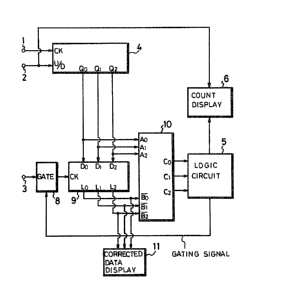
Fig. 10 shows a further embodiment of the tape
position display apparatus according to the invention. In
Fig. lO, parts corresponding to those of Fig. 7 are marked
with the same references and are not described in detail.
A counter 15 in Fig. 10 has a clock terminal CR to
which the second pulses P2 are supplied from the~tenminal~3.
~he output Dc (R2, Rl Ro) of the counter 15 representing the
digits 22, 21 and 2 is supplied to the subtracter lO, in
: ~ ' ,,
~7~ 5 S03077
PATENT
which it is subtracted fxom the output Di (Q2' Q1' Q0) of
the counter 4. An identifying circuit 16 receives a signal
C2, Cl, C0 = K(K2, X1, Ko~ resulting from phase-inverting
the MSB (most significant bit) of the output Do (C2, C1, C0)
from the subtracter 10 by an inverter 17. The iden~ifying
circuit 16 compares the signal K(K2, K1, Ko) with a
reference signal J(J2' J1' Jo)(= nl~ (binary notation) = 4
(decimal notation)). In this case, K =Do + 4 is
established. The up/down counter 15 for counting the second
pulsa P2 from the terminal 3 is controlled by the output
~rom the identifying circuit 16. To be more concrete, when
J ~R, the counter 15 i5 operated in the up-count mode, while
when J = X, the counter 15 stops its count operation.
Figs. 8A to 8N and 9A to 9N illustrate the
operation of the tape position display apparatus of Fig. 10.
In these figures, Di represents the output from the counter
~, Dc represents the output from ~he counter 15, and Do
represents the output form the subtracter 10.
First the operation of the tape position display
apparatus in a case in which the tape TP ~Fig. 4) is
transported in the positive direction will be considered.
As Figs. 8A, 8B, 8C and 8F show, when Do = 3, if the second
pulse P2 is produced, the counter 15 is set in the up-mode
because X = 7 so that the output Dc from the counter 15 is
changed from 7 to 0. Thus Dc = 0 is subtracted from Di = 2
in the subtracter 10 so that the output Do is decreased by 1
(from 3 to 2) immediately. ;
As Figs. 8A, 8B, 8C and 8F show, when Do = 2, if
the second pulse P2 is produced; the counter 15 is set in
the up-mode because K = 6 so that the output Dc from the
. ~ .
~23-
~ ....,"' ~ . '
.~',: ' , i
~ ~ 7~ 5 PATENT
counter 15 is chang~d from O to 1. Thus Dc = 1 is
subtracted from Di = 2 in the subtracter 10 so that the
output Do is decreased by 1 (from 2 ~o 1) immediately.
As Figs. 8A, 8B, 8C and 8F also show, when Do = l,
if the second pulse P2 is produced, the counter 15 is set in
the up-mode since K = 5 so that the outpu~ Dc from the
counter 15 is changed from 1 to 2. Thus Dc = 2 ls
subtracted from Di = 2 in the sub~racter 10 so that the
output Do is decreased by 1 (from 1 to 0) and coincides in
phase with the sacond pulse P2. Thereater, even if the
second pulse P2 is produced when Do = O, g - 4 is
established so that the output Dc from the counter 15
remains unchanged and thus Do = O also remains unchanged.
As Figs. 8H, 8I, 8J and 8M show, when Do = 5, if
the second pulse P2 is produced, the counter 15 is set in
the down-mode since K = 1, so that the output Dc ~rom the
counter 15 is changed from 5 to 4 t whereby Dc = 4 ls
subtrac~ed from Di = 2 in the subtrac~er 10. The output Do
is immediately increased by 1 (from 5 to 6). (In clock
arithmetic, modulo eight, 2 - 4 = 6.~
~ s Figs. 8~, 8I, 8J and 8M show, when Do = 6, if
the second pulse P2 is produced, the counter 15 ls set in
the down-mode since K = 2, so that the output Dc from the
counter 15 is changed from 4 to 3, whereby Dc = 3 is
subtracted from Di = 2 in the subtractPr 10. The output Do
is immediately increased by 1 (from 6 to 7). (In clock
arithmetic, modulo eight, 2 - 3 = 7.)
As Figs. 8H, 8I, 8J and 8M also show, when Do = 7,
~f the second pulse P2 is produced, the counter 15 is set in
the down-mode since ~ = 3, so that the output Dc From the
-2~
.
.
`'.
`. '' ..... .
S03077
~ ~ 7 ~ PATENT
counter 15 is changed from 3 to 2, whereby Dc = 2 is
subtracted from Di - 2 in the subtracter 10. The output Do
is immedia~ly increased by 1 (from 7 to 0) and coincides in
phase with the second pulse P2. (In clock arithmetic,
modulo eight, 7 ~ 1 = 0.)
Next an explanation will be given of the operation
OI the tape position display apparatus in a case in which
the tape TP (Fig. 4~ is transported in the opposite
(reverse) direction. As Figs. 9A, 9B, 9C and 9F show, when
Do = 4, if the second pulse P2 is produced, the counter 15
is set in the down-mode since K = 0, so that the output Dc
from the counter 15 is changed from 1 to 0, whereby Dc = 0
ls subtracted from Di = 5 in the subtracter 10. The output
Do is immediately increased by 1 (from 4 to 5).
As Figs. 9A, 9B, 9C and 9F show, when Do = 5, if
the second pulse P2 is produced, the counter 15 is set in
the down-mode since K = 1, so that the output Dc from the
counter 15 is changed from 0 to 7, whereby Dc = 7 is
subtracted from Di = 5 in the subtracter 10. The output Do
is immediately increased by 1 (from 5 to 6). (In clock
arithmetic, modulo eight, 5 - 7 = 6.)
As Figs. 9A, 9B, 9C and 9F show, when Do = 6, if
the second pulse P2 is produced, the counter 15 is set in
the down-mode since K = 2, so that the output nc from the
countex 15 is changed from 7 to 6, whereby Dc = 6 is
subtracted from Di = 5 in the subtracter 10. The output Do
is immediately increased by 1 (from 6 to 7) and coincides in
phase with the second pulse P2. (In clock arithmetic,
modulo eight, 5 - 6 = 7.1
-25-
:. . :.. ,:: ; . ,,
. ~ . .: .. : . , :
7~ ~'t~ S03077
PATENT
As FigsO 9H, 9I, 9J and 9M show, when Do = 2, if
the second pulse P2 is produced, the counter 15 is set in
the up-mode since x - 6, so that the output Dc from the
coun~er 15 is changed from 3 to 4, whereby Dc = 4 is
subtracted from Di = 5 in the subtrac~er 10. The output Do
is thus immediately decreased by 1 (from 2 to 1~.
As Figs. 9H, 9I, 9J and 9M also show, when Do = 1,
if the second pulse P2 is produced, the counter 15 is set in
the up-mode since K = 5, so that the output Dc from the
coun~er 15 is changed from 4 to 5, whereby Dc = 5 is
subtracted from Di = 5 in the subtracter 10. The output Do
is thus immediately decreased by 1 (from 1 to 0) and
coincides in phase with the second pulse P2.
The tape position display apparatus shown in Fig.
10 may be modified so that the counter 15 is a 24-scale
counter having outputs R3, R2, R1, ~0 respectively
representing digits 23, 22, 21, 2. The outputs R3, R2, R
(Dc) of the most significan~ three digi~s are supplied to
the subtracter lO. ~s a result, it requires two second
pulses P2 supplied to the counter 15 to change the outputs
R3, R2, R1, so that the phase of the output Do from the
subtracter 10 changes more slowly. If the scale of the
counter 15 is selected to be more than 25 and the outputs of
three higher digits are fed to the subtracter 10, the phase
of the output Do from the subtracter 10 changes much more
slowly.
Thus there is provided ln accordance with the
invention a tape position display apparatus particularly .
adapted for use with a VTR, an audio tape recorder and the
-26-
. ~ ,
~ ~ 7~ PATENT
like. The tape position display apparatus of the invention
can detect and display the tape position with high accuracy.
Many modifications of the preferred embodiments of
the invention will readily occur to those skilled in the art
upon consideration of this disclosure. The invention is
therefore limited only by the appended claimsO
i;
. ~
~ 27~
, ;.. , . ,.. ;..... .. ~ ; ,