Note: Descriptions are shown in the official language in which they were submitted.
~7~
MULTILAYER NONWOVEN FABRIC
BACKGROUND OF THE INVENTION
The present invention relates to a nonwoven
fabric having at least two layers of nonwoven web.
More particularly, the present invention relates to a
nonwoven fabric wherein at least one of the layers com-
prises a web having monofilaments or fibers with a
bilobal cross-section as well as methods ~or making
such multilayered nonwoven fabrics.
Nonwoven materials are, of course, well known
in the art. Such materials were developed primarily in
the l950's and 1960's, although at least one reference
dates bac~ to 1943 (see, e.g., U.S. Patent No. 2,336,743
to Manning).
One o~ the most significant commercial applica-
tions of nonwoven fabrics is in the fabrication ofdisposable products intended for a sinqle use. T~pical
of su~h products are disposable diapers~ feminine care
products, surgical gowns, industriaL wipes, and the
like. Because the nonwoven fabric is intended as a
,
cloth substitute in these applications, extensive
effort has been expended to improve the properties of
nonwoven fabric to more nearly approximate that of
cloth. Of particular interest has been the softness of
the nonwoven fabric, that is, improving the feel or
"hand" of the fabric together with lowering the
resistance of the web to folding or bending, ~nother
~731.
-- 2
important area has been the improvement of the nonwoven
web's tensile strength or tear resistance. 'fet another
areas has been the development o nonwoven fabrics with
specific wettability characteristics. With the few
exceptions noted below, these efforts to improve the
properties of nonwoven webs has focused almost ex-
clusively on the use of fibers having a circular
. cross~section.
U.S. Patent No. 2,336,743 to Manning describes
a method and apparatus for solution spinning or melt
spinning nonwoven fabrics. According to the specifica-
tion, the spinning material can be extruded through
orifices in the spinneret, which orifices may be slits,
circular, or of other cross-section.
U.S. Patent No. 3,314,840 to Lloyd et al.
relates to a process and apparatus for producing a non-
woven fabric. Although the disclosure appears to relate
primarily to solution spinning, it does not appear to
exclude melt spinning. The spinneret preferably has
circular or slit openings, although such openings may
have other shapes such as circles, triangles, crescents,
etc.
U.S. Patent No. 3,508,390 to Bagnall et al.
relates to a modified filament and fabrics produced
therefrom. While the emphasis of the disclosure is on
the preparation of conventional knitled fabrics, nonwoven
fabrics are also mentioned. The filament has a cross-
section consisting of three integrally joined, substan-
tially sImmetrical legs, thereby forming a substantially
uniform ~-shaped cross-section having defined dimensions.
U S. Patenl No. 3,509,009 to Hartmann relates
to a nonwoven abric which is prepared by meltspinning
fiber-forming high polymers into a directed gass current
of high velocity to produce a uniform nonwoven fabric
of great strength. While the filaments produced in
accordance with the described invention are typically
~L27~)2~
3 -
of circular cross-section, other cross-sections are
mentioned, such as star~shaped, 'f-shaped, or a combina-
tion thereof.
An apparatus for producing nonwoven fleeces
is described in U.S. Patent No. 3,528,129 also to
Hartmann. The patent appears to be an improvement of
an exlstin~ apparatus by specifyinq holes in the spinneret
which have a branched cross-section. ~ shaped and T-shaped
holes are specifically mentioned.
Finally, U.S. Patent No. 3,630,816 to Parker
relates to nonwoven sheets made ~rom filaments having a
rectangular cross-section. The rectangular cross-sec~ic-.
of these filaments ls specficed to have an aspect ratio
of at least 3:1.
SUMMARY OF THE I~ENTION
It is a general object of the present inven-
tion to provide a nonwoven fabric with improved softness
and tensile strength. It is also a general object of
the present invention to provide a method of producing
such a nonwoven fabric. It is a more specific object
of the present invention to provide a nonwoven liner
for a disposable diaper which has improved softness,
tensile s~rength, and moisture transfer capacity. It
is another specific object of the present invention to
provide a nonwoven wrap for a catamenial device which
likewise has improved sotness, tensile strength, and
moisture transfer capacity.
These and other objects are accomplished by
the present inven~ion by providing a nonwoven fabric
comprising at least two layers of nonwoven web. r ach
nonwoven web comprises a plurality of monofilaments of
a thermoplastic material. In at least one of the webs
the monofilaments have a bilobal cross-section. By the
term "bilobal" the inventors intend to refer to a shape
including an elongate and substantially rectangular
-- 3 --
~t7~2~
- 4
portion which has at each of it5 furthest separated
ends an enlarged portion which is typically circular
and which enlarged portion has a diameter greater than
the thickness of the rectangle. It has been found by
the present inventors that a nonwoven web made with
such bilobal shaped monofilaments provides remarkably
increased softness as well as other desirable
properties and particularly that such a "bilobal" web
has many desirable properties when used in a multilayer
structure.
In accordance with one of the preferred embodi-
ments, the nonwoven fabric consists of two layers of a
nonwoven web. The nonwoven web of the first layer com
prises a plurality of substantially identically prepared
continuous and substantially randomly deposited monofila~
ments of a thermoplastic polymer, which monofilaments
have a bilobal cross-section. The nonwoven web of the
second layer likewise comprises a plurality of substan-
tially identically prepared continuous and substantially
randomly deposited monofilaments of a thermoplastic
polymer, with the exception that the monofilaments of
the second layer most preferably have a trilobal or
branched cross-section.
In addition, the nonwoven fabric of this pre-
ferred e~bodiment is stabilized by discrete compactedareas of thermally induced filament bonds extending
through a major portion of both webs, with these com-
pacted areas distributed in an intermittent regular
pattern and constituting from about 10 to about 30
33 percent of the area of the fabric. Also in accordance
wlth this preferred embodiment, the thermoplastic
material is a polyolefin. Most preferably, the
polyolefin is polypropylene, polyethylene, or an
ethylens-propylene copolymer.
In accordance with another of the preferred
embodiments, the nonwoven liner for a disposable diaper
is constituted similarly to the preerred e~bodiment
mentioned immedia~ely above, with the stipulation that
the first layer with bilobal filaments is intended to
fit next to the wearer. Also, the second layer is used
as a transfer layer to enhance the transfer of moisture
through the nonwoven fabric and into the underlying
absorbent material. This is accomplished by adding a
wetting agent to the polyolefin monofilaments to
thereby make the second layer which would otherwise be
hydrophobic, somewhat hydrophillic or wettable. This
addition can be done by mixing a wettinq agent with the
polymer before it is extruded or, more preferably, it
can be done by applying a solution of the wetting agent
to the nonwoven web after it is formed.
In accordance with still another of the prefer-
red embodiments, the nonwoven wrap or a catamenial
device is likewise oriented with the first layer next
to the wearer. Also, the second or transfer layer is
made wettable in the same manner as the preferred embodi-
ment of the nonwoven liner for a disposable diaper.
In accordance with yet another of the prefer-
red embodiments, the method of forming the nonwoven web
of each layer includes the following steps. The polymer
is preferably extruded while in a melted state throu~h
a splnneret plate with a multiplicity of holes with the
desired cross-section, thereby producing a plurality of
monofilaments with approximately the same cross-section.
These monofilaments are then drawn, preferably pneumati-
cally. After drawing, the monofilaments are laid down
on a moving belt in an essentially random orientation
with respect to each o~her.
At this point in the preferred method, the
web of each layer can be joined to each other in one of
the following three ways. The first and most preferable
involves the use o parallel web formers, i.e.
spinnerets together with drawing apparatus. In this
-- 5 --
~L~7~
. ~
-- 6 --
way, the first former lays down a nonwoven web on a
laydown belt just ahead of the point where the second
former lays down its web. As a result, the second web
is laid down on top of the first and the two continue
through the remaining processing steps together. The
two webs are then slightly compacted by passin~ through
a pair of compaction rolls. Next, the two webs are
bonded together and stabilized by passing through a
pair of oppositely rotating heated rolls, the first of
which has a smooth surface, and the second of which has
a raised pattern. As a result, the two webs become
thermally bonded in discrete areas arranged in a
patter~ which corresponds with the raised pattern of
the one heated roller. Preferably, the pattern of
thermally bonded areas is formed so as to constitute
about lO to about 30 percent of the surface of the
nonwoven fabric.
The second method of joinlng also involves
the use of two parallel formers as in the first, with
the exception that the first laid down web passes
through thermal bonding ro].ls as described above before
the second web is laid on top of it. The two webs,
i.e. one bonded and one not, are then slightly
compacted and pass through a second pair of the-mal
bonding rolls. Preferably, in the interest of optimum
softness, this second palr o thermal bonding rolls
creates a bonded pattern in the two webs which occupies
a lower percentage of multi- layer fab.ic than the
bonded pattern of the first laid down web.
The third method of joining in~olves îorming
the first laid down web in a prio~ s~ep and then
winding it up. The fabric is then made by unrolling
the first laid down web onto the belt on which the
second laid down web is deposited. The two webs are
then processed as described above.
~;~7~
~ 7 -
BRIEF_~ESCRIPTION OF THE DRAWINGS
Flgure 1 i5 a schematic diagram of the prefer-
red apparatus for produciny the multilayered nonwoven
fabric of the present invention.
Figure 2 is a schematic diagram of an alterna-
tive apparatus for producing the multilayered nonwoven
fabric of the present invention.
Figure 3 is a schematic diagram of another
alternative apparatus for producing the nonwoven fabric
of the present invention.
Figure 4 shows a bottom perspective view of a
spinneret plate with bilobal shaped orifices to thereby
extrude monofilaments of bilobal cross-section.
Fi~ure 5 is a bottom and enlarged view of two
of the bilobal shaped orifices of the spinneret plate
of Figure 4.
Fisure 6 is a bottom view of a trilobal shaped
orifice in a spinneret plate.
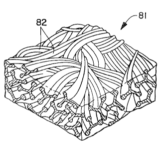
Figure 7 is an illustration in partial cross-
section of a nonwoven web with monofilaments of bilobal
cross-section.
Figure 8 is an illustration in partiaL cross
section of a nonwoven web with monofilaments of trilobal
cross-section.
~igure 9 is a cross-section of a portion of a
disposable diaper made with the nonwoven liner of the
present invention.
Figure 10 is a partial cross-section o a
catamenial device made with the nonwoven wrap of the
present invenr on.
Figures lla-c represent various patterns of
intermi~tent heat bonding which can be applied to the
nonwoven fabric of the present invention.
- 8
DETAILED DESCRIPTION
In its broadest terms, the present invention
comprehends a multilayer nonwoven fabric with at least
two layers of norlwoven web, at least one of which
comprises a plurality of monofilaments or fibers of a
thermoplastic material, which monofilaments or
filaments have a bilobal cross-section. In particular,
the cross-sectional shape of these bilobal
monofilaments can be described as including an elongate
substantially rectangular portion which has at each of
its furthest separated ends a substantially circular
portion which has a diameter greater than the thickness
of the rectangle. This shape could also be described
as that of a "dogbone" or "dumbell".
In general, each web can be prepared from
noncontinuous fibers, continuous monofilaments, or a
combination thereof. The preferred method of producing
each web is by spunbonding techniques, although meltblown
techniques which produce noncontinuous fibers are also
considered to be within the scope of this invention.
At present, the continuous monofilaments produced by
spunbonding techniques, are preferred.
The thermoplastic material of each web can
either be the same or a different material from that of
the other web. Each thermoplastic material must be
capabie of being spun into monofilaments. While it is
contemplated to use spinnable materials such as glass,
as a practical matter, it is preferred to use polymeric
materials in both webs. Examples of such polymers, by
way of illustration only, include polyolefins, polyamides,
polyesters, polyurethanes, polyvinyl acetate, polyvinyl
chloride, pol~fvinyl alcohol, polyacrylonitrile,
polymethyl methacrylate, polyethyl acrylate, cellulose
acetate, viscose, and the like. In addition, the
thermoplastic material can be a homopolymer, a
copolymer, or a blend or two or more polymers. At
8 -
present, homopolymers, copol~fmers, and polymer blends
of the polyolefins are preferred, with copalymers and
homopolymers being more preferred. The most preferred
homopolymers are polypropylene and poLyethylene, and
the most preferred co-polymer is an ethylene/propylene
copoLymer.
It is an important ad~antage of the present
invention that certain materials which mi~ht not have
optimum properties in a nonwoven web for various
reasons, may be used in the present invention in
combination with a web made from a different material
to produce a better set of properties. For example,
polyethylene is generally considered too soft and
plastic for certain nonwoven web appLications.
Howev~r, in ollowing the teaching o the present
invention, a nonwoven web made from polyethylene can be
bonded to a stronger nonwoven web, such as one made
rom polyprop~lene, to thereby make a more desirable
web. At present, such a pairing is most preferred.
That is, the most preferred embodiment comprises a
nonwoven web made from polyethyLene bonded to a
nonwoven web made from polypropylene. This partic~lar
nonwoven fabric shows increases in both softness and
tensile stren~th.
FIGURE l is a schematic diagram showing the
preferred apparatus for forming such polymers into non-
woven webs. With one exception, this apparatus is made
in accordance with the ~eachings of U.S. Patent No.
4,405,297 and operated in accordance the teachin~s of
30 4,340,563, both to Appel and Morman.
The exception is that instead of just one web ~orme~,
i.e~ spinneret and quenching/drawing apparatus, there
are two such ormers 11 and 12 in the abrication Line.
The first or~er 11; lay's down a irst web 13 on the
_ 9
.,
12~
- 10 -
moving belt 15, while the second former 12 lays down a
second web 14 on top of the first web 13.
While this is the preferred confi~uration for
the web formers, other types of web formers are also
available. ~or example, an alternative embodiment
orms a nonwoven web with the apparatus and method
described in U.S. Patent No. 3,692,618, to Dorschner et
aL.
Briefly, each of the nonwoven web formers 11
and 12 shown in FIGURE l include a spinneret box 21
which receives a polymer in a melte~ state. As mentioned
above, the polymer which goes into each web may or may
not be the same. The temperature o each polymer melt
is selected so as to make it sufficientLy fluid or
spinning. For example, when the polypropylene is being
spun, the preferred temperature is about ~60F. When
polyethyLene is being spun, the preferred temperature
is 375F. Pressure is applied to each poly~er meLt to
thereby push it through the holes or orifices in the
spinneret plates 22 and 23 to thereby orm the curtains
o monofilaments 24 and 25 respectively. Each curtain
24 and 25 falls through a quench chamber 2G and Z7 where-
in it is contacted by quench air. The quench air in
each former is supplied at a relatively low pressure,
but such that there is sufficient pressure to also
cause a degree of drawing of the monofilaments when
they pass through the drawing nozzles 28 and 29.
Upon exitin~ the lower end of the drawing
nozzle 28, the first curtain of monofilamen~s 24 is
laid do~n on a moving foraminous surface lS, such as an
endless screen or belt, to form a irst nonwoven web
13. Upon exiting the lower end o the drawing nozzle
29, the second curtain of monofilaments 25 is laid down
3S on top of the irst nonwoven web 13 to form a second
- nonwoven web 14.
' - 10-
~ .,.
~.~7~24
The two webs 13 and 14 then pass through a
pair of compacting rollers 19 and 20 which slightly
compact the filaments in the webs to thereby increase
the integrity of the webs and to aid in further pro~
S cessinq.
The two webs 13 and 14 next pass through the
two heated bonding rolls 21 and 22. These rolls are
preferably made and ope~ated in accordance with the
teachings of U.S. Patent No. 3,855,046, to Hansen and
Penning~, ~riefLy, the apparatus and process
described therein includes the use of two rolls 21 and
22, at least one of which and preferakly both o which
are heated. The lower roll has a smooth surace while
the upper roll 21 includes a raised intermittent pattern
on its surace. In alternative embodiments, the
bonding rolls can be reversed so that the roll with the
pattern is under the web; thereby contacting the first
laid web.
As the two webs 13 and 1~ ~ass between these
two heated rolls, each web becomes stabili~ed by the
ormation of discrete compacted areas o thermalLy
induced ilamen~ bonds which extend throu~h a major
por~ion of the thickness of the web. These com~acted
areas are distributed in an intermittent pattern cor-
respondin~ to the raised pattern o the roll 21 andprovide unbonded filament spans therebetween. In addi-
tion, the two webs 13 and 14 become bonded together
into the bilayered nonwoven fabric 18.
FIGURES lla-llc iLLustrate three patterns
which can be used on the roll ~1 and result in the same
patterns on the nonwoven abric 18. Fi~ure lla
includes circular areas arranqed in hexaqons and
triangLe3. Fi~lre llb includes circular areas arranqed
in a repeatin~ hourqlass coni~uration. Fi~ure llc,
which is the presently preferred pattern, incLudes
~ 12 -
equilateral diamond shaped areas which are arranged in
staggered rows.
Two parameters of concern in regard to the
specific pattern that is used are the si~e of the com-
S pacted areas formed and the distance between the areas.These two parameters together affect the percentage of
area on the web which becomes bonded. It is important
that the percentage of bonded area be great enough to
insure sufficient integrity of the web for its intended
use. In addition, it is important that the percentage
of bonded area not be too qreat, as a higher bonded
area usually produces a web with reduced softness. At
present, it is preferred to have a bonded area between
about 10 and about 30 percent of the surface area of
lS the fabric. A range of about 12 to about 20 percent
bonded area is more preferred, while about 17 percent
is most preferred.
Another important factor relating to the bond-
ing of the webs is the temperature at which the rolls
21 and 22 are maintained. Naturally temperatures below
a certain point for each polymer will not effect any
bonding, while temperatures above another point will
melt too much of the web. Also, it has been obser-~ed
the temperature of the rolls can affect both the tensile
strength as well as the softness of the web produced.
In particular, within a certain range, higher tempera-
tures will produce a web with higher tensile strength.
However, these same higher temperatures can produce a
web with decreased softness. This is likely due to a
higher and lower degree of bonding which occurs within
this range of temperatures. That is, ~he higher tem-
peratures likely rssult in a more and stronger inter-
filament bonding which is beneficial to tensile strength
and somewhat detrimental to softness. At present, the
preferred bonding temperature for polypropylene monofila-
- 12 -
3l~7~2~
. . ~ ~ .
- 13 -
ments is between about 220 and about 320aF. A
temperature of about 275F is most preferred.
After the fabric 18 is bonded by rolls 21 and
22, it is wound on the take up roll 23. Alternatively,
it may be desirable to design this apparatus to connect
with a fabrication line for the end product.
The basis weight of the nonwoven fabric
. produced can be readily varied depending on the
intended use of the web. For example, the nonwoven
fabric can be made from about 0.3 to about 3 oz./square
yard. Although in alternative embodiments, the basis
weight of the first web may be made greater than that
of the second, or vice versa, the preferred embodiment
includes a irst and second nonwoven web of equal basis
weight. A preferred basis weight for a disposable
diaper liner, i.e. with both layers, is about 0.~
oz./square yard and a preferred basis weight for a non-
woven wrap for a catamenial device is about 0.4
oz./square yard.
FIGURE 2 is a schematic diagram showing an
alternative apparatus for producing the bilayered non-
woven fabric of the preferred embodiment. This apparatus
is identical to the apparatus depicted in FIGURE 1 with
one exception. The excep~ion is that between the first
former 111 and the second former 112, there is included
an additional pair of compaction rolls ll9 and 120 together
. with an additional pair of bor.ding rolls 221 and 222
which stabilize the first web 113 in .he manner discussed
above. Also, instead of one collec~ on belt 115, there
is an additional belt 215 which picks up the first non
woven web 113. These compaction and bonding rolls 219-222
are configured and operate the same as those described
above with the exception that they are set for compacting
and bonding a single nonwoven web.
After being compacted and bonded, the first
nonwoven web 113 is picked up by the collection belt
- 13 -
~x~
- ~ -
~ 14 -
115 after whlch the second nonwoven web 114 is laid
down on top of it. The two nonwoven webs, i.e. the
bonded web 113 and the unbonded web 114, pass through
the compaction rollers 119 and l~0. Next, they pass
through the oondin~ rollers 121 and 122 where the second
web 114 is stabilized and the two webs 113 and 114 become
bonded together into a bilayered nonwoven fabric 118.
The fabric 118 is then rolled up on the take up roll
123.
FIGURE 3 shows anothar alternative apparatus
for producing the multilayered nonwoven fabric. In
this apparatus, a first nonwoven web 313 is supplied
from roll 301. At this point, the nonwoven web 313 can
be either bonded or unbonded. Bonded is preferable.
The web 313 passes along the collection belt 315 where-
upon the second web 314 is laid on top of it. The two
webs then pass through the compaction rolls 319 and 320
and then pass through the bonding rolls 321 and 322
where either both or just the second web becomes stabil-
ized and the two webs 313 and 314 become bonded together
as described above to form the bilayered nonwoven fabric
318.
In discussing the embodiments described in
connection with FIGURES 2 and 3, it should be noted
that, if the first laid down web is bonded before the
second laid down web is placed upon it, the bond pattern
used when the two webs are put together should be selected
in consideration of the bond pattern already used on
the first laid down web. It is desirable to have the
second bond pattern not overlap the first. Therefore,
if the second bonding pattarn is the same as the first,
it should be offset. However, in the interest of web
softness, it is preferred to have the second bond pattern
different from the first and particularly to occupy a
lower percenta~e of the web than the first. Naturally,
- 14 -
~7~
' `~
- 15 --
the final bond pattern through the first laid down web
will ~e a sum of the first and second bonding. Accord-
ingly, this also favors a lower percentage for the second
bonding pattern.
As a point of clarification, it should be
noted that the term first lald down web refers to the
web which has been formed earlier in the processing
, line or alternatively to the web which has been made
and rolled up in a previous step. It should also be
noted that as used herein, and particularly in the
claims, the terms "first web" and "second web" are
arbitrary designations which do not necessarily refer
to their order of forming. The order of laying each
web and the particular polymer used will depend on the
end use of the fabric.
It is an advantage of the present invention
that the first laid down web can have a higher percentage
area bonding pattern than the second laid down web. In
this way, the first laid down web can possess sufficient
tensile strength while the second laid down web can
possess more softness. This is beneficial, for example,
in a nonwoven web for a disposable diaper wherein the
second laid down web can be used for increased softness
on the "bodyside" of the diaper while the first laid
down web can provide increased tensile strength for the
liner.
~ IGURE 4 is a bottom perspective view of the
spinneret plate 41 with bilobal shaped orifices 42. It
is through these orifices 42 that the polymer is-extruded.
The monofilaments produced consequently have a cross-
section with a bilobal, "dogbone" or "dumbell" shape.
It has been found by the inventors that a multilayered
nonwoven fabric produced with one of its layers being a
nonwoven web with bilobal shaped monofilaments e.Yhibits
particular advantages.
~L27~
- 16 -
Because the nonwoven fabri.c of this invention
can be made with the bilobal monofilaments in either
the first or the second laid down web, this bilobal
spinneret plate can be in either of the formers shown
S in FIGURES 1-3. For reasons to be discus9ed below, it
is presently preferred to place the bilobal spinneret
plate in the second former of the apparatus described
above. That is, it is presently preferred to have the
monofilaments with the bilobal cross-section in the
second laid down web.
The spinneret plate of the other former can
have orifices of any desired shape. It is believed
that having the bilobal monofilaments in one layer of
the fabric provides at least some degree of improvement
regardless of the shape of the monofilaments in the
other layer. Circular orifices are, of course, most
common and it is clearly contemplated to use circular
monoilaments in one of the layers of the fabric. In
addition, in certain embodiments it is desirable to
have both layers of the fabric with bilobal monofila-
ments. At present, the most preferred shape of the
cross-section of the monofilaments of the other, i.e.
nonbilobal, web is referred to as Y-shaped. Figure 6
shows a 'f-shaped orifice for making such filaments.
~he spinneret plate 12 is made with a width
slightly greater than the width to be produced. The
preferred width of the web will vary depending on the
end use to made of it. For example, a nonwoven web
made to be used as a liner for disposable diapers is
preferably about 12.5 inches wide.
The num~er of orifices is selected and the
orifices are arranged in the plate at the prescribed
spacing in such a way so as to provide the desired den-
sity of filaments in the web. ~t present, it is prefer-
red to have between about 30 and about 100 orifices in
the spinneret plate per inch of web width. Most
- 16 -
7~2flt
- 17 -
preferable is about 85 orifices per inch of web width.
For examples, a 12 inch spinneret plate, i.e. one that
will form a 12 inch wide nonwoven web, there are most
preferably 1020 orifices.
FIGURE 5 is an enlarged view showing the pre-
ferred configuration of two of the orifices 42 of the
spinneret plate 41. The dimensions and proportions of
the bilobal orifices are not known to be critical, pro-
vided that they produce monofilaments which have the
bilobal shaped cross-section accordin~ to the present
invention. Currently, the preferred configuration of
the orifice is as follows. The shortest dimension is
the thickness of the elongate portion a. The diameter
b of the substantially circular portions 25 and 26 is
approximately twice that of the thickness a. The length
c of the orifice 24 is approximately ten times that of
the thickness a. In the most preferred embodiment, the
thickness a is 0.215 mm, the diameter b is 0.430 mm and
the length c is 2.15 mm. Certainly, these dimensions
and proportions can be varied in alternati~Je embodiments
depending on factors such as specific polymer which is
extruded and the desired properties of the nonwoven
web.
As mentioned, the preferred spacing between
orifices will depend on the density of the nonwoven web
to be produced. In the most preferred embodiment, the
space d between orifices is 7.25 mm. Also, the preferred
orientation of the orifices is such that all of the
orifices are arranged parallel to each other and that
their length c is aligned in the direction in which the
belt 17 moves (i.e. machine direction).
FIGURE 6 is bottom enlarged view of a
Y-shaped orifice for a spinneret plate. The inventors
have observed that monoilaments produced by this
orifice retain a Y-shaped cros~-section even after
drawing. The inventors have also observed that
- 17 -
``" 127~L~32'~
- 18 -
nonwoven webs made with such Y-shaped monofilaments
have increased stiffness, i.e. less softness than those
made with circular or bilobal monofilaments. However,
the i.nventors also observed that the web producsd with
Y shaped monofilaments with increased tensile strength
over those produced with circular monofilaments. As
mentioned above, it is most preferred to have the
nonbiLobal layer be a web with Y-shaped monofilaments.
This is currently thought to be desirable to obtain a
- 10 fabric with both increased softness as well as
increased tensile strength.
FIGURE 7 is an illustration of a section o$
nonwoven web 71 made with bilobal monofilaments. This
nonwoven web could be either the first or second laid
down web in the processes described above, and would
become part of the multilayer nonwoven fabric of the
present invention. As can be seen the web comprises a
number of continuous monofilaments 72 which are randomly
oriented with respect to each other. It is desirable
for the monofilaments to undergo a high degree of looping
and overlapping in the web. These properties are
influenced by factors such as the density of the monofila-
ments that are laid down, the speed at which the monofila- -
ments are laid down, etc.
As can be seen, the monofilaments of this web
71 each have a bilobal cross-section. The dimensions
of the ~ilobal cross-section are not known to be critical,
provided that the basic features of such cross-section
are present. That is, the cross-section of the monofila-
ments includes a subs~antially rectangular portion which
has at each of its furthest separated ends an enlarged
portion which typically is substantially circular.
As mentioned above, the monofilaments are
drawn after beinq extruded through the spinneret plate
41. As a result, they typically have dimensions less
than that of the orifices 42. The amount of this reduc-
- 18 -
- 19 -
tion will depend on factors such as the specific polymer
extruded, the rate of quenchin~ the monofilaments, the
drawing force applied to the monofilaments, etc. In
the preferred embodiment wherein polypropyl9ne is used,
the monofilaments typically end up with a cross-sectiOn
length of between about 30 and about 60 microns. Most
preferably, the cross-sectlon length is about 40
microns, although this will vary depending on the
desired properties of the nonwoven web.
FIGURE 8 is an illu~tration similar to that
of FIGURE 7 with the exception that the monofilaments
shown have the Y-shaped cross-section. As mentioned,
in the most preferred embodiment, one o the nonwoven
web~ would have this type of monofilaments.
Figure 9 is a cross-section through a dis-
posable diaper 91. The nonwoven liner 92 is positioned
on the side of the diaper 91 which will be placed next
to the infant's body. As shown, the liner 92 consists
of two layers 93 and 94. In the most preferred embodi-
~0 ment, the bodyside layer 93 comprises monofilaments
with the bilobal cross-section, while the other layer
94 comprises monofilaments with the Y-shaped cross-
section. Alternatively, the layer 94 can comprise bi-
lobal monofilaments. The rnajor portion of the diaper
consists of a layer 95 of an absorbent material such as
fluCfed cellulose pulp. Naturally, this layer 95 is
intended to absorb moisture. In additlon, a mois~ture
impermeable layer 96 is included.
An important property of the liner 92 is its
softness. In particular, it is important for the liner
~2 to be both extremely pliable as well as soft to the
touch in consideration of the infant's comfort. The
present inventors were somewhat surprised to observe
that a nonwoven liner made with the bodyside layer com-
prising the monoilaments of bilobal cross-section exhi-
bited remarkably improved softness over the prior art
- 19 -
- ~o
nonwoven liners made with rnonofilaments of circular
cross-section.
One test which the inventors have used to
evaluate the softness o nonwoven fabrics is called the
"Smeltnik Stiffness Test". In this test a piece of
nonwoven fabric is placed on top of an open cylinder.
A hemispherical probe with a diameter slightly less
than the inside diameter of the cylinder is then dropped
from a standard hei.ght to thereby push the nonwoven
fabric down into the cylinder. The distance that the
probe travels into the cylinder is then measured and
recorded as an indication o the softness, i.e.
pliability or drapability of the fabric. As a
comparison, while a nonwoven diaper liner made with
circular monofilaments recorded a distance of 155 mm
into the cylinder, a nonwoven diaper liner made with
monofilaments of the same material but having a bilobal
cross-section recorded a distance of 370 mm. Thus, a
dramatic increase of the softness of the fabric was
shown.
Another aspect of softness which is important
particularly in diaper liners is the "hand" or softness
to the touch. While a specific test for this property
is not presently available to the inventors, they as
well as others have observed an increased softness to
the touch of the nonwoven web made with the monofilaments
of bilobal cross-section, which web is preferably placed
on the bodyslde of the diaper 91.
Ano~her property of a nonwoven liners and
nonwoven fabrics in general is tensile strength, i.e.
the resis~ance to tearing. This property has been meas-
ured by the present inventors on a device which grips a
piece of a nonwoven fabric in a pair of jaws, and then
pulls it apart. The force needed to break the fabric
is recorded as the grab tensile strength. This test
can be performed either with the fabric oriented in the
- 20 -
.. ~ - .
Lt~
.~
- 21 -
jaws so that the force is applied parallel to the
direction in which the fabric was laid down (machlne
direction, MD), or with the fabric is oriented so that
the force is applied perpendicular to the direction in
S which the web was laid down (cross direction, CD). All
of the values for tensile strength reported herein
refer to machine direction (M~) strengths.
The inventors were pleased to observe that
the nonwoven fabrics which had one layer of a nonwoven
web with bilobal monofilaments showed increased tensile
strength. While not wishing to be bound by any particular
theory, it is currently believed that this increased
tensile strength may be a result of the increased contact
area available between filaments when they are thermally
bonded as described above. Also, as mentioned above,
the tensile strength of the multilayer fabric is in-
creased when the first laid down web has a higher bonding
area percentage. It is also believed that the tensile
strength is improved when a bilobal web and Y-shaped
web are used in a multilayer fabric, possibly due to
the increased contact area for thermal bonding.
Yet another property which is particularly
important when the web ls used as a liner for a dispos-
able diaper is the wettability o the liner. Depending
on the design of the diaper, it is usually deslrable to
have the liner be at least partially wettable in order
to facilitate passage of the moisture through to the
absorbent layer. In addition, it is even more desirable
to provide a wettability gradient in the liner whereby
moisture can be wicked away from the wearer. In particu-
lar, it is most preferred to provide a bodyside layer
which is less wettable than the "transfer" layer, i.e.
the layer next to the absorbent material. In this way,
mois~ure flows more easily ~hrough to the absorbent
material than it flows back to the wearer.
- 21 -
7~
- 2.2 -
Many of the pol~mers which are 5uita~1e to
make nonwoven webs are hydrophobic. Specifically, the
two most preferred polymers, pol~propylene and poly-
ethylene are completely hydrophobic. As a result, it
is desirable to take steps to increase the wettability
o~ nonwoven webs made with these polymers.
It is known in the art that wettability can
be increased by the addition of wetting aqents such as
surfactants. ParticuLarly, cationic, anionic, and non-
ionic surfactants may be added to materials to therebyma~e the material wettable. In one preferred embodimen~
of the present invention, the polypropylene monofilaments
are made wettable by adding a nonionic surfactant to
the monofilaments. This can be done by mixing the
surfactant with the pol~mer before it is extruded, i.e.
"internal addition". The wetting agent is preerrably
mixed with the polymer in an amount of up to about S
percent by weight o the polymer. 'n addition, it has
been ound that with a pol-lmer such as pol~propylene,
it is beneicial to heat the nonwoven web at some stage
to thereby effect migra~ion of the wetting agent to the
surface o the mono~ilaments. Such a heating process
which is used to bring an internally added lubricant to
the monofilament surface is described in U.S. Patent
Nos. 3,~73,068 and 4,070,218 to Weber.
Naturally, the temperature to which the web is heated
should be below the meLting point of the monofilaments.
An advan~age o the present inventio~ is that
it is possible to produce the described wettability
~radient by addin~ the desired amount of wetting agent
to the polymer which will ~o into the nonwo~en web of
the transfer layer. The web of the bodyside layer can
either have no wetting a~ent, less wettin~ a~ent, or a
less e~ective wettin~ a~ent added.
- ~3 -
As an alternative to the internaL application,
the wetting agent can be applied in a solution to the
nonwoven web after it is formed, i.e. "exterior appli-
cation". This application can be carried out by
dipping either each nonwoven web or both nonwoven webs
together into a solution of the wetting agent, after
which the solvent is evaporated to thereby leave an
amount o~ the surfactant on the surface of the web or
webs. It may also be desirable to heat the web to more
quickly evaporate the solvent. ~lternatively, the
solution of surfactant may be applied to the web by
spraying, or by rotogravure printing. In both cases,
the evaporation of the solvent may be hastened by
heating the web. Naturally, it is desirable for the
evaporation to be complete before the web is wrapped on
the wind up roll. In all three exterior application
methods, the surfactant is applied so as to end up with
up to about 5 percent by wei~ht of the web.
As with internal application, it is preferable
to selectively apply the wetting agent to produce a
wettability gradient. This can be done by applying the
wettiny agent to either one or both of the webs before
they are joined. Alternatively, it can be done by use
of different materials in the webs so that the wetting
agent is more effective when applied to the transfer
layer than it is when applied to the bodyside !ayer.
The inve~tors observed that a web with
Y-shaped monofilaments proved superior as a transfer
layer than one with either bilobal or circ~lar
monofilaments. It is currently believed that this
result is due to the increased bulk, i.e. lower
density, of the web made with Y-shaped monofilaments
which thereby provides a greater surface area for
moisture absorption.
Still another property which is important in
a nonwoven fabric for a liner is its opacity or hiding
- 23 -
~7~2~
- 24 -
power. It is a known practice in the art to add minor
amounts of titanium dioxide to the pol~fmer melt in
order to increase the opacity of nonwoven fabrics. The
inventors have found that the nonwoven fabric produced
according to the present invention has an lncreased
opacity, possibly due to the increased surface area of
the bilobal and/or Y-shaped monofilaments which could
; reflect ~ore light.
EIGURE 10 shows a cross section through a
typical catamenial device such as a feminine napkin
101. As shown, the pad consists of a nonwoven wrap 102
which surrounds an absorbent portion 105. The wrap
consists of two nonwoven webs 103 and 104. Most of the
properties which are desirable for the nonwoven liner
for a disposable diaper are likewise desirable to have
in the nonwoven wrap for a catamenial device. In parti-
cular, it is significant that the present invention
provides a nonwoven web with increased softness, i.e.
both drapability and smoothness to the touch. Accord-
ingly, it is likewise preferred to have the web withthe bilobal shaped monofilaments on the body side of
the device. Also, it is typically important to enhance
the wettability of the wrap 102, most preferably with a
wettability gradient. This may be done by adding a
wetting agent to the one or both of the webs in the
wrap by metho~s such as those described in connection
with the diaper liner abo~e.
EXAMPLES
EXAMPL~ 1 was run on an apparatus such as
that described above in connection wi~h FIGURE 1. In
particular, the web width was 12 inches and the first
spinneret plate had 50 bilobal shaped orifices per inch
of width and the second spinneret plate had 5~ bilobal
shaped orifices per inch of width. Polypropylene was
extruded through the first spinneret at a melt
- 24 -
- 25 -
temperature of about 460E~. Polypropylene was extruded
through the second spinneret at a melt temperature of
about 460F. The basis weight of the first laid down
web was 0.4 oz./square yard. The basis weight of the
second laid down web was 0.4 oz./square yard. The two
webs were bonded together with the pattern shown in
FIGURE lla having a bonding area about 22.5 percent of
the web area. The temperature of the bonding rolls was
approximately 270F.
The resultant fabric had a Smeltnik Stiffness
Test (SST) value of 160 mm. In addition, the fabric of
this example was measured for grab tensile strenqth by
placing a piece of the web between oppositely pulling
grippers. The force needed to tear the web was in the
lS direction at which it was laid down (machine direction
or MD) was 13 lbs.
EXAMPLE 2 was run similarly to Example 1 except
that the apparatus used was that describcd in
connection with FIGURE 3. The first laid down web was
bonded at about 270F with the pattern of lla at about
22.S% bond area. The second web was laid down on top
of the first laid web and then bonded with about 3%
bond area. The first laid down web was made wettable
by rotogravure printing a solution of nonionic
surfactant.
The resultant abric had an SST value of
200 mm, and a MD tensile strength of 10 lbs. In
addition, a test was performed to measure the "run-off"
value of this fabric. This test consists of placing an
8 to 10 inch piece of the web on top of an absorbent
batt which were both oriented at a 4Sa angle. Then,
100 ml of water was poured onto the fabric at a point 6
inches from the bottom. The amount of water which ran
off the bottom without being absorbed was measured and
recorded. For Example 2, the value was 5.5 ml.
~2~V~
. .
26 -
EXAMPLE 3 was run similarly to Example 2
except that the first laid layer was not bo~ded before
the second was laid on top of it. The resultant fabric
had an SST value of 315 mm, an MD tensile strength of
12 lbs., and a run-off value of 3Ø
EXAMPLE 4 was run similarly to Example 2
except that the first laid web was bonded at 250F
before the second web was laid on top of it. The two
webs were bonded together with a bond area of about
6.6%. The resultant fabric had an SST value o 430 mm,
an MD tenslle strength of 8 lbs., and a run-off value
of 2.9 ml.
EXAMPLE 5 was run similarly to Example 2
except that the cross-section of the first laid web was
Y-shaped and that the first laid web had a nonionic
surfactant added internally. The two webs were bonded
together at about 260F. The resultant fabric had an
SST value of 300 mm, an MD tensile strength of 6 lbs.,
and a run-off value (with the Y-shaped layer as the
transfer layer) of 22.5.
EXAMPLE 6 was run similarly to Example S
except that the first laid web had round monofilaments
and the basis weight of the second laid web was
0.5 oz./square yard. The resultant fabric had an SST
value of 220 mm, an MD te~sile strength of 9 lbs., and
a run-off value of 71 ml.
EXAMPLE 7 was run similarly to Example 2
except that the first laid layer and second laid layer
each had a basis weight of 0.5. The monofilaments of
the first laid layer were ~-shaped and had a nonionic
surfactant added internally. The second layer was
extruded through a spinneret plate with 30 orifices per
inch. The final bonding temperature was about 280F.
The resultant fabric had an SST value of 230 mm, an MD
tensile strength of 12 lbs., and a run-off value of 30 ml.
- 26 -
- 27 -
EXAMPLE 8 was run similarly to Example 1
except that polyethylene was extruded through the
second spinneret with '~-shaped orifices at a melt
temperature of about 375F. The basis weight of the
S second laid web was 0.6 oz./square yard. The two webs
were bonded together at about 225F with about 24% bond
area. The resultant web had an SST value of 325 mm,
and an MD tensile strength of 9.5 pounds.
While the invention has been described in
connection with specific embodiments thereof, it is
evident that many alternatives, modifications, and
variations will be apparent to those skilled in the ar~
in light of the foregoing description. In particular,
although the nonwoven webs of the invention have been
described in connection with liners for disposable dia-
pers and with wraps for catamenial devices, other types
of products such as surgical and other disposable gar-
ments, industrial wipes, and the like, are clearly
contemplated. In addition, although the described
embodiments have all had only two iayers of nonwoven
webs, fabrics with three or more layers are considered
within the scope of the invention. Accordingly, it is
intended to embrace all such alternatives, modifications,
and variations as fall within the spirit and broad scope
of the appended claims wherein the designation of first
and second are arbitrary and not rela~ed to the order
of forming or the position of the webs.
- 27 -