Note: Descriptions are shown in the official language in which they were submitted.
~71V54
--1
"ROTARY/LINEAR CONVERTOR"
~ l~ls invention relates to a device for
converting linear motion to rotary motion and
vice-versa. For example, the principles of
this invention may be applied to a fluid operated
engine or motor and particularly to such a device
which is capable of producing rotary motion
of a shaft to power motor vehicles, farm machinery,
and stationary devices such as pumps, heat exchangers,
generators and so on.
In particular, the engine or motor of this
preferred application is capable of being operated
by a wide range of fluids and in fact may be
operated with any type of expandable fluid,
whether or not prior ignition is required. Thus,
lS the device may be operated wi~h a compressed
i~ or pressurised fluid such as air, steam or helium
which is allowed to expand, or alternatively
the motor may be operated with fluids such as
~ petrol, gas or other hydrocarbon-or similar
fuel which require ignition to cause the necessary
expansion. Conversely, when operated as a pump, -
_
27~054
I
--2--
the device of this invention may be used topump or compress both liquid and gaseous fluids.
In Australian Patent Specification No. 501555,
there is described a fluid operated device comprising:
a cylinder member, at least two mutually opposed
piston members movable axially therein, a working
chamber within said cylinder member defined
by opposing ends of said piston members and
the inner wall of said cylinder member, said
10 cylinder member being provided with inlet and
outlet means communicating with said working
chamber for admission of working fluid to said
chamber and for removal of spent working fluid
from said chamber, respectively; a shaft member
15 extending through said piston members and said
cylinder member concentrically with said members;
first coupling means coupling the piston members
to one of the other mentioned members such that
axial reciprocation of the piston member causes
20 rotation of the piston members relative to said
one of the other mentioned members; second coupling
means coupling the piston members to the other
mentioned members to prevent relative rotation
of the piston members and said other one of
25 the other mentioned members while permitting
axial reciprocation Of the piston members; and
valve means in said working chamber operatively
coupled to said shaft member for rotation with
said shaft member relative to the cylinder member
30-to control movement of working fluid into and
out of said working chamber through said inlet
and out~et means. In particular embodiments
disclosed therein, the first coupling means
comprises at least one continuous sinusoidal
~2-7~054
guidway formed in a surface of either the piston
member or the cylinder member, and at least
one associated cam follower mounted in a facing
~ surface of the cylinder member or the piston
member, respectively, to project therefrom and
engage the guideway; and the second coupling
means of these embodiments comprises at least
one axially extending guideway formed in a surface
of the piston member or the shaft member, and
10 at least one associated cam follower mounted
in a facing surface of the shaft member or the
piston member, respectively, to project therefrom
and engage the guideway. In alternative embodiments,
the arrangement of the first and second coupling
15 means is reversed in that the first coupling
means comprises at least one continuous sinusoidal
guideway formed in a surface of the piston member
or the shaft member, and at least one associated
cam follower mounted in a facing surface of
20 the shaft member or the piston member, respectively,
to project therefrom and engage the guideway;
and the second coupling means comprises at least
one axially extending guideway formed in a surface
of the piston member or the cylinder member,
2S and at least one associated cam follower mounted
in a facing surface of the cylinder member or
the piston member, respectively, to project
therefrom and engage said guideway.
It is an object of the present invention
- 30 to provide an improved rotary~linear convertor
which is relatively_simple in construction and
more efficient. According to the present invention
there is provided a rotary/linear convertor
comprising;
a first member and a guide, said first
member having a central axis and being adapted
.
-: - lX~10s4
- --4--
~ for linear movement in the direction of said
central axis within or along said guide;~
a second member adapted for rotational
- movement;
connecting means operatively interconnecting
said f irst and second members so that respective
linear or rotational movement of one said member
~ causes respective linear or rotational movement
of the other said member;
characterized in that said connecting
means comprises;
a connecting shaft disposed eccentrically
of said central axis of said first member;
first coupling means operatively connecting
15 said first member to said connecting shaft
such that axial reciprocation of said first
member causes orbital movement of said connecting
shaft and vice versa;and
second coupling means operatively connecting
- 20 said connecting shaft to said second member
so that said orbital movement of said connecting
shaft causes rotation of said second member
and vice versa.
Preferably the first coupling means comprises
25 a sleeve operatively connected to the first
member for axial reciprocation therewith that
sleeve being associated with the connecting
shaft for axial reciprocation relative thereto
and at least one link member extending between
- 30 the sleeve and a mounting which is in a fixed
position. The position of the mixed mounting
- may be adjustable if desired.
Preferably the second coupling means comprising
a disc-like member mounted f or rotation about
35 an axis, ehe connecting shaft being eccentrically
-
~ -
_
1271054
s--
connected with respect to that axis to the
- disc-like membe-r, the second member being operatively
connected to the disc-like member.
In one form the, first coupling means comprises
a plurality of link members extending between
the sleeve and respective mountings which are
fixed. Preferably each link member is pivotally
connected to said sleeve and to the mounting
for limited universal movement.
In one arrangement the second member is
operatively connected to the disc-like member
co-axially therewith. In another arrangement
the second member is radially displaced from
the axis of the disc-like member and operatively
15 connected thereto by transmission means. Preferably
, the disc-like member comprises a circumferential
gear section adapted to engage a further gear
which is operatively connected to the second
member.
Preferably the first member comprises
a piston and the guide comprises a cylinder
having a working chamber therein. Inlet means
and outlet means are provided for communicating
with the working chamber for the admission
25 and removal of the working fluid therefrom.
In one preferred form the first member comprises
two pistons disposed within the cylinder there
being a single working chamber disposed between
said pistons.
The device may further include a lubricating
and/or cooling system comprising a delivery
channel in the connecting shaft and the second
coupling means for delivering lubricant and/or
coolant from externally of the converter to
35 the first member so that the orbital movement
of the connecting shaft assists in distributing
,
.
- . - 127~054
.
--6--
the fluid at selected positions at or around
the first member. The fluid may be circulated
by a pu~ping action or centrifugal force.
Further features of the present invention
will be apparent from the following description
of preferred,embodiments as illustrated in
the accompanying drawings.
In the drawings:
Figure 1 is a longitudinal section through
a first embodiment of a motor constructed in
- accordance with the present invention (taken
along line I-I of Figure 2);
Figure 2 is a cross-sectional view along
the line II-II of Figure l;
Figure 3 is a longitudinal section through
a second embodiment of a motor which is constructed
in accordance with this invention;
Figure 4 is a cut-away perspective view
of a unit of the present invention;
Figure 5 is a perspective sketch of a
single piston, an associated shaft, and their
interconnections, partly cut-away at the central,
longitudinal section thereof, this sketch being
partly schematic; and
Figure 6 illustrates (in a partly sectional,
partly schematic drawing) the use of two links
between a sleeve on the connecting shaft connected
to a piston and respective mounting points
for the links on the engine or pump housing.
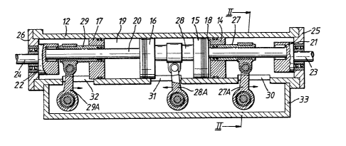
Means (not shown) such as openings in
~ the cylinder which may be provided with suitable-
valving arrangements may be provided to communicate-
with each of the working chambers 18 and 19
for admission of working fluid to each chamber
35 and subsequent removal of working fluid therefrom.
The working fluid may either be a fluid under
1~ 0~.4
.
--7--
pressure, ~for example, a pressurised gas such
as air or steam or a pressurised liquid such
as hydraulic oilj or a fluid which expands
on ignition. In the latter case, each working
chamber may also be provided with a suitable -
ignition device of any known type.
Shaft 20 extends eccentrically of the
cylinder 12 and is eccentrically mounted at
each end on the inner faces of disc members
21 and 22. Mounted concentrically on the outer
faces of disc members 21 and 22 are output
shafts 23 and 24, shafts 23 and 24 being mounted
for rotation by suitable bearing means in end
walls 25 and 26, respectively, of the cylinder
12.
Each of the pistons 14, 15 16, 17 is coupled
to shaft 20 such that axial reciprocation of
the pistons causes orbital movement of the
shaft within cylinder 12. As depicted in Figures
1 and 2, this coupling comprises sleeves 27,
28 and 29 surrounding shaft 20 and axially
reciprocable thereon. It will be noted that
whilst pistons 14 and 17 are mounted at one
end of each of sleeve 27 and 29 respectively,
pistons 15 and 16 are mounted one at each end
of single sleeve 28 for movement in unison
- of these pistons. Thus, expansion of a working
fluid within working chamber 18 will move plston
14 and sleeve 27 to the right, and piston 15
and sleeve 28 to the left, from the positions
-as shown in Figure 1. This movement can be
utilised to exhaust spent working fluid from
chamber 19 by movement of piston 16 also to
the left and movement of piston 17 and sleeve
29 to the right, in addition to rotation of
- 127~
,
.
the discs 21 and 22 on orbi-tal movement of
shaft 20 and hence rotation of output shafts
23 and 24 as will now be described.
Discs 21 and 22 are caused to rotate an
5 axial movement of sleeves 27, 28 and 29 along
shaft 20 by means of reciprocating link arms
27A, 28A and 29A which extend through longitudinal
slots 30, 31 and 32 respectively in the cylinder
12. Each of the link arms is pivotally mounted
at one end thereof to a respective one of the
sleeves 27, 28 and 29, and at the other end
thereof at a fixed point externally of the
cylinder 12 within a longitudinally extending
housing 33. (If desired, the embodiment illustrated
may be modified so that this fixed point is
internally of the cylinder 12). As will be
apparent from Figure 2, each link arm 27A,
28A and 29A is mounted within housing 33 to
not only reciprocate axially of the cylinder
but also is pivotal in the transverse direction
thereto. It will be appreciated that because
of the link arms, as each sleeve is forced
axially of the shaft 20, the shaft will be
forced to perform an orbital movement, for
example in the direction of arrow A in Figure
2, hence the discs 21 and 22 and output shafts
23 and 24 will be rotated.
If desired, the pivot point for each of
the link arms 27A, 28A and 29A can be varied
within the housing 33 or cylinder 12. This~
wil~ have the-effect of varying the compression
within working chambers by altering the top
and bottom dead centre positions of the pistons.
In addition, variation of the length of these
link arms will enable the length of the "stroke"
.
1~7~054
g
to be selected as desired.
- TuEning now to Figure 3, the fluid operated
motor illustrated is in many respects similar
to the motor illustrated in Figures 1 and 2.
Thus, it comprises a cylinder 112, pistons
114, 115, 116 and 117 movable axially therein
and defining working chambers 118 and 119. In
this embodiment, however, four shafts 120,
121, 122 and 123 are provided eccentrically
10 Of the cylinder 112, and sleeves 124, 125,
126 and 127 are axially reciprocable on respective
ones of these shafts, each of these sleeves
having a respective one of the pistons 114,
115, 116 and 117 mounted thereon. It will
15 be appreciated that the respective pistons
and sleeve could be one piece. Link arms 128,
129, 130 and 131 extend pivotally between a
respective sleeve and an external pivot point
as described and shown in detail in Figures
20 1 and 2. It will be seen in Figure 3, however,
that shafts 120, 121, 122 and 123 are mounted
eccentrically on one face of a respective toothed
disc 132, 133, 134 and 135, each of which is
mounted for rotation~within the cylinder 112.
25 Discs 132, 133, 134 and 135 each mesh, through
-an appropriate aperture in the wall of cylinder
112 with external gears 136 mounted on external
output shaft 137. Thus, orbital movement of
shafts 120, 121, 122 and 123 caused by axial
30movement of pistons 114, 115, 116 and 117 and
sleeves 124, 125, 126 and 127 on expansion
or contraction of working chambers 118 and -
119, and link arms 128, 129, 130 and 131 is
transmitted as rotary motion to the output
3sshaft 137.
If desired, an external output shaft equivalent
27105~
,
, . .
--10--
to output shaft 137 of Figure 3 may be incorporated
into the embodiment of Figures 1 and 2, such
a shaft being mounted for example on the side
of the cylinder 12 opposite to the housing
33. Similarly, a single through-shaft equivalent
to shaft 20 of Figure 1 may, if desired, be
incorporated into the embodiment of Figure
3 in place of the half shafts 120, 121, 122
and 123.
Referring to Figure 4 there is shown an
arrangement comprising a cylinder 112, two
pistons 114 and 115 disposed therein with a
working chamber therebetween. The interconnection
between the pistons 114 and 115 to the output
15 shaft 137 is the same and, as such, only the
parts for piston 114 have been itemized. The
piston 114 is operatively connected to an
eccentric sleeve 124 which is reciprocable
on connecting shaft 120 which in turn is connected
20 to disc-like member 132. A link member 128
extends between the sleeve 124 and a mounting
point which is fixed but enables limited universal
movement of the link member 128 relative thereto.
The disc member 132 has an external gear section
25 which is connected to gear wheel 138 which
in turn is operatively connected to shaft 137.
The operation of the device shown in Figure
4 is the same in principle to that described
earlier. Working fluid is adapted to enter
30 and be discharged from the working chamber
between the pistons so that power can be transmitted
to output shaft 137.
Referring to Figure 5, there is~shown
a cylinder 12 with a piston 14 moveable axially
35 therein. The face or crown 14A of piston 14,
with the face or crown 15A of a second piston
_
,
- ~2710~4
15 mounted within cylinder 12, and with the
inner wall of cylinder 12, defines a working
chamber 19 in cylinder 12. This arrangement
-is essentially the same as that shown in Figure
4. Other components of the portion of the
engine depicted in Figure 5 all having corresponding
features described earlier in the specification
(and thus requiring no further explanation)
are shaft 20 which is eccentric of cylinder
12, sleeve 29, disc 21, output shaft 24, housing
33, link arm or link 27, slot 30 in cylinder
12, and pivotal mounting arrangement 34 which
includes a shaft 35 connected to housing 33.
The operation of an engine or pump having these
features will be apparent from the earlier
description.
As shown, there is provided in shaft 24,
disc 21 and shaft 20 of at least one channel
~a single channel 40 is shown in Figure 5)
through which a fluid can pass, to enter the
region in cylinder 12 which is located between
the back of piston 14 and the disc 21, and/or
to enter other parts of the engine. To permit
the fluid to enter the region between piston
14 and the disc 21, at least one aperture 41
will be provided in shaft 20 and its surrounding
sleeve 29, to provide a passage to enable the
fluid to leave the channel 40.
-The fluid which flows through channel
. 30 40 will normally be a lubricant (such as oil),
: a coolant or a gas which also cools the pistons
of the engine.
If the fluid is oil, it will normally
enter the sump of the engine, in the bottom
of housing 33, through the slot 30. If the
,
27~054 - -
.
fluid is a gas, it will also leave the inside
of cylinder 12 through slot 30, to be vented
to atmosphere through an aperture or valve
in housing 33. If the interior of the housing
33 is to be maintained at a pressure which
is greater than atmospheric pressure, the venting
to atmosphere will be through a valve.
If the fluid is to be used only to cool
the pistons, aperture 41 will be omitted and
the fluid will be supplied, via orifice 42
which connects with channel 40, to the hollow
interior region 14B of piston 14. The coolant
fluid will then leave region 14B via (a) a
second channel running parallel to channel
40, (b) at least one aperture 43 in the rear
of piston 14, or (c) at least one aperture
(not shown in the drawing) which is located
in the side wall of piston 14, rearward of
the compression piston rings. It will be appreciated
that in some applications no piston rings would
be necessary. If this coolant is, or contains,
oil which is also used for lubrication, it
may leave the region 14B via at least one aperture
located in the side wall of piston 14 rearward
25 of the compression piston rings but forward
of the scraper or oiler ring (if present). Aperture
43 may be provided with a v-alve to control
the flow of coolant.through the aperture.
In another arrangement, the aperture may be
30 omitted thereby providing a cushioning effect
on the stroke.
The fluid may be pumped through channel
40, or it may be circulated through channel
40 by the combination of one-way valves and
35 the reciprocal movement of the piston 14, or
. .
- ~Z71~54
-13-
it may be circulated solely by the reciprocal
movement of the piston 14. The same arrangements
may`bè adopted if the fluid has to flow through
more than one channel, or in one direction
through one channel and in the reverse direction
through another channel. If one-way valves
are used, they may be positioned in any suitable
location in the flow path of the fluid.
Referring to Figure 6 there is shown a
modification which comprises the use of a plurality
of links or link arms 50 connected to each
sleeve 29. It should be noted that sleeve
29 is normally attached to shaft 20 in such
a manner that there is no rotational movement
between shaft 20 and sleeve 29. Thus it is
not essential that shaft 20 has a circular
cross-section. The circumference of a section
Lhrough the shaft 20 may be circular but with
one or more chords replacing part of the circle,
or it may be elliptical, or hexagonal, or the
shape of any other polygon, or (in general
terms) any continuous or interrupted conic
section. Desireably, the bearing surface 23
on which the connection to one end of link
25 moves, has a circular cross-section using a
shaft 20 having a non-circular cross-section,
one end of which is seated in a small well
in the back of piston 14, prevents the tendency
of the side of the piston 14 to touch the inner
30 wall of cylinder 12 during rotation of the
piston.
The ends of link.arms 50 which are remote
from sleeve 29 are connçcted to respective
pivotal mounting points connected to rods 55
35 mounted on to the housing 33 of the engine.
_
__
2710~;4
.
.
-14-
An alternative arrangement (not shown in the - ~
drawings) is to provide a mount to receive
each rod 55, respectiveiy, b'y af,fixing a bracket - '
(or a plurality of brackets) to the exterior
of the cylinder 12, with the (or each) bracket
having at least one bearing point adapted to
receive an end of a rod 55.
The use off two or more links 55 improves -
the smoothness of operation of the engine,
10Another feature that may be incorporated
into engines and pumps of the type discussed
above is the mounting of the shafts 20 and
20A (see Figure 1) of an opposed pair of pistons
14, 15 so that the axes of shafts 20 and 20A
are not substantially co-linear. Preferably,
the shafts 20 and 20A are mounted so that their
axes lie on different radial planes passing
through the axis of cylinder 12. More preferably
shafts 20 and 20A ~re mounted so that their
axex lie on radial planes of cylinder 12 which
are 1-80~ apart (that is, they lie on a diametral
plane of cylinder 12).
Yet another feature that may be incorporated
into engines or pumps of this type is the shaping
of the crowns or faces of the opposed pistons
in such a manner as to achieve maximum turbulence
or swirl of the combustion gases (or combustion
aerosols or other type of combustion fluid)
in the case of an engine, or of the gases,
liquid or slurry in the case of a pump.
.
! 35