Language selection

Search

Patent 1271093 Summary

Third-party information liability

Some of the information on this Web page has been provided by external sources. The Government of Canada is not responsible for the accuracy, reliability or currency of the information supplied by external sources. Users wishing to rely upon this information should consult directly with the source of the information. Content provided by external sources is not subject to official languages, privacy and accessibility requirements.

Claims and Abstract availability

Any discrepancies in the text and image of the Claims and Abstract are due to differing posting times. Text of the Claims and Abstract are posted:

  • At the time the application is open to public inspection;
  • At the time of issue of the patent (grant).
(12) Patent: (11) CA 1271093
(21) Application Number: 586936
(54) English Title: LIFE RING
(54) French Title: BOUEE DE SAUVETAGE
Status: Deemed expired
Bibliographic Data
(52) Canadian Patent Classification (CPC):
  • 114/66
(51) International Patent Classification (IPC):
  • B63C 9/08 (2006.01)
  • B63B 21/08 (2006.01)
(72) Inventors :
  • PANOSSIAN, RAFFY (Canada)
(73) Owners :
  • PANOSSIAN, RAFFY (Canada)
(71) Applicants :
  • PANOSSIAN, RAFFY (Canada)
(74) Agent: HENDRY, ROBERT G.
(74) Associate agent:
(45) Issued: 1990-07-03
(22) Filed Date: 1988-12-22
Availability of licence: N/A
(25) Language of filing: English

Patent Cooperation Treaty (PCT): No

(30) Application Priority Data: None

Abstracts

English Abstract


ABSTRACT OF THE DISCLOSURE
A hollow seamless flotation device having spaced loops of
rope known as grab lines which extend the ends of which extend
through tubular passages molded in the hollow body. A recess
in an inner side face of the body adjacent each tubular passage
and which also includes a blind hole , receives a knot on the
end of the rope and the end of the rope is received in the
blind hole to provide further resistance to pulling the knot
through the tubular passage.


Claims

Note: Claims are shown in the official language in which they were submitted.


I claim

1. A hollow seamless flotation device having an attached
grab line, said device comprising: a hollow body, a pair of
tubular passages extending through the body interconnected at
their ends on one side face of said body by a recess larger than
said tubular passage and provided with a blind hole adjacent each
tubular passage so that a knot on line extending through said
passage will be received in and fricitonally retained in said
recess and an end of said line associated with said knot will be
received in an adjacent blind hole.


2. A seamless flotation device as claimed in claim 1
wherein said hollow body is filled with foamed plastic.


3. A seamless flotation device as claimed in claim 1
wherein said flotation device is a ring.

4. A hollow seamless flotation device as claimed in any
one of claims 1,2 or 3 molded of polyethylene.

5. A hollow seamless flotation device as claimed in any
one of claims 1 ,2 or 3 molded of high density polyethylene by
slush molding.


Description

Note: Descriptions are shown in the official language in which they were submitted.


~27~09~


This invention relates to hollow flotation devices and
more particulary to a buoyant safety device adapted to have a
grab line detachably secured thereto.


Flotation devices known as ring life buoys or life
rings are provided on boats, wharfs or beside swimming pools.
These life rings have loops known as grab lines at spaced intervals
around the periphery which can be grabbed by a person in the
water. Since such devices may be subjected to weathering and
stress it is important that they be rugged and dependable.
Accordingly the life rings and the attached grab lines must pass
strict official tests such as Coast Guard certification tests.


A common problem with life rings is that the grab lines

or the fastening of these lines to the ring is susceptible to
deterioration, damage or malfunction. Maximum force which can be
applied to the grab line without damage or longitudinal dis-
placement of the line is one of the tests to be met for official
approval.


Examples of prior art attempts to resolve the problem of
attaching grab lines include U.S. Patent No 3,032,789. J.S.
Fedorowicz which discloses a grab line loops passin3 through the
body of the ring and passing around an insert forced into a
recess in the ring and U.S. Patent No. 3,594,836 to James H.
Robertson which discloses a strapless ring buoy having loops
coated with heat reactive adhesive bonded to polystyrene within


,,,

1~7~093


the body of the molded ring. U.S. Patent No. 3,~50,754 to J.H.
LeBlanc and U.S. Patent No. 3,445,868 to L.P. Frieder also show
embedded line securing means.


It will be appreciated that it would be preferable to
provide a life ring grab line which can be readily replaced if
worn or damaged which cannot be accidentally disconnected or
displaced.


It is therefore an object of the present invention to
provide a life ring having a recess therein to receive and secure
the ends of a grab line.


A further object is the provision of an inexpensive grab
line attaching means which enables the grab line to be replaced
when necessary.


Accordingly the present invention provides a hollow
seamless flotation device having an attached grab line. The
device comprising a hollow body adapted to be filled with foamed
plastic, a pair of tubular passages extending through the body
interconnected at their ends on one side of the body by a recess

larger than the tubular passage and provided with a blind hole
adjacent each tubular passage so that a knot on the line
extending through the passage will be received in and
frictionally retained in the recess and an end of the line
associated with the knot will be received in an adjacent blind
hole.


A
..

1271~93


In the drawings which show a preferred embodiment of
the invention
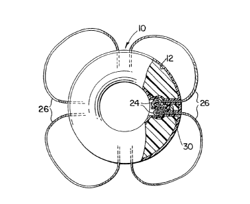
Figure 1 is a top plan view of a life ring in accordance
with this invention
Figure 2 is a cross sectional view of a portion of the
life ring of Fig~re 1
Figure 3 is a cross sectional view taken along the line
3 - 3 of Figure 1 and
Figur 4 is a sectional view of an alternative grab line.


Referring now in detail to the drawings a flotation
device in the form of a life ring 10 has a hollow body 12 adapted
to be filled with suitable foamed plastic material 14. The
hollow body is preferably molded as by a technique known as slush
molding and comprises a suitable plastic such as high density
polyethylene.


Pairs of tubular passages 20 extend through the ring 10
at intervals. Four pairs of passages 20 are shown however the
number may vary according to the size and purpose for which the
floatation device intended. Each of the tubular passages 20 has
an interconnects with a recess 22 on an inner side of said ring
10. me recess 22 is larger than the tubular passage 20 to
accommodate a knot 24 formed in a grab line 26. A blind hole 28

in the recess 20 is provided adjacent each of the tubular passages
20 to receive an end 30 of the grab line 26.


.. . .

~7~093


m e grab line knots 24 shown in Figure 1 are of a type
ccmmonly known as a figure eight knot. However, other configur-
ations are possible such as that shown at 32 in Figure 4, wherein
the end 30 o$ the line 26 is passed through strands of the line
26 to form a loop 34. m e end 30 of the line 26 extends into the
blind hole 28 in the recess 22.


It will be noted that the recess is slightly narrower
opening in cross section and thereby frictionally engages a knot
24 or 32 forced into the recess. Preventing inward movement of
the grab line 26 is one of the requirements of an acceptable life
ring 10 ensuring that loops 26 will be readily accessible at all
times.


Another consideration is the ability of the grab line
attaching method to resist being pulled out. In this regard
attention is drawn to the converging tubular passages 20 adapted
to change the direction of the force applied to the grab line 26
so that a straight pull will be less likely to occur thus reducing
strain on the knot 24. Due to the provision of the blind hole 28
to receive the end 30 there is further resistance to pulling the
knot 24 or loop 32 through the tubular passage 20.


,' ' ! :, :,

1~710~t~3
_ 5

This resistance of the knot 24 or loop 32 to undoing
is due in part to the knot 24 or loop 32 being further
from the end ~30 of the line 26. Providing more secure
attaching means in this manner is necessary to comply with
Coast Guard or other safety regulations which may apply.


~
,,
~, . .

Representative Drawing
A single figure which represents the drawing illustrating the invention.
Administrative Status

For a clearer understanding of the status of the application/patent presented on this page, the site Disclaimer , as well as the definitions for Patent , Administrative Status , Maintenance Fee  and Payment History  should be consulted.

Administrative Status

Title Date
Forecasted Issue Date 1990-07-03
(22) Filed 1988-12-22
(45) Issued 1990-07-03
Deemed Expired 1995-01-03

Abandonment History

There is no abandonment history.

Payment History

Fee Type Anniversary Year Due Date Amount Paid Paid Date
Application Fee $0.00 1988-12-22
Maintenance Fee - Patent - Old Act 2 1992-07-03 $300.00 1992-09-29
Maintenance Fee - Patent - Old Act 3 1993-07-05 $100.00 1993-07-05
Owners on Record

Note: Records showing the ownership history in alphabetical order.

Current Owners on Record
PANOSSIAN, RAFFY
Past Owners on Record
None
Past Owners that do not appear in the "Owners on Record" listing will appear in other documentation within the application.
Documents

To view selected files, please enter reCAPTCHA code :


To view images, click a link in the Document Description column. To download the documents, select one or more checkboxes in the first column and then click the "Download Selected in PDF format (Zip Archive)" or the "Download Selected as Single PDF" button.

List of published and non-published patent-specific documents on the CPD .

If you have any difficulty accessing content, you can call the Client Service Centre at 1-866-997-1936 or send them an e-mail at CIPO Client Service Centre.


Document
Description 
Date
(yyyy-mm-dd) 
Number of pages   Size of Image (KB) 
Drawings 1993-10-07 2 51
Claims 1993-10-07 1 24
Abstract 1993-10-07 1 13
Cover Page 1993-10-07 1 10
Description 1993-10-07 5 126
Representative Drawing 2001-10-12 1 11
Fees 1992-09-29 1 39
Fees 1993-07-05 1 42