Note: Descriptions are shown in the official language in which they were submitted.
~L~7~ 8
Back~round of the Invention
This invention relates to transmission synchronizer
clutch systems of the type including axially opposed
blocker ringsO The rings ha~e opposed friction surfaces
positioned for engaging like surfaces on jaw clutch
members of selective gears rotatable about a common shaft
within the transmission housing. More particularly, the
invention retates to spring pins disposed for facilitating
engagement of such friction surfaces in response to the
selective actuation of a manually operated shifting
mechanism.
Synchronizer clutches of the coacting type are well
known in the art of medium duty transmissions. Such
clutches are effective to synchronize jaw clutch members
prior to contact with and engagement of gear teeth in
order to provide shifting without clashing of gears. The
spring pins typically facilitate engagement of ~he blocker
rings by initially and resiliently moving the friction
surfaces into engagement under a relatively low force in
response to the incipient engaging movement of the
transmission shifting mechanism. ~owever, most of the
spring pins systems commonly and currently utilized
consist of a plurality of parts, many including separate
pin and spring members. The prior art spring pins are
made typically of stampings and require subsequent
assembly of component parts. Even with respect to the
simpler prior art structures, the fatigue lives of such
spring pin parts have been relatively low.
~ ~7~L~4~
S~mmary of the lnvention
The spring pin of the present invention presents a
novel, unitary body formed of spring steel, and is
considerably simpler to manufacture than most prior art
spring pin systems. In addition, the use of spring steel
per se provides a significantly improved fatigue life,
providing up to four hundred thous~nd cycles. In a
preferred form, the spring pin is disposed for operation
in a double-acting synchroniæer clutch system which
includes two axially opposed blocker rings having axially
aligned bores for receiving and seating respective ends of
the spring pin. The spring pin defines an elonga~ed
S-shaped body, each end of which defines a bight portion
and a spring leg portion spaced from the bight portion in
its normally unstressed position. Also in the preferred
form, oppositely extending outside leg portions of the
spring pin each contain a pair of symmetrically opposed
detents positioned intermediate ~he ends of the spring pin
body for engagement of a shifter flange. The flange is
directly coupled to a shifter mechanism and is hence
manually operated to effect synchroniæation and subsequent
gear engagement.
Fig. 1 is a fragmentary cross-sectional view of a
transmission which includes a double-acting clutch
synchronizer incorporating a preferred embodiment of the
present invention,
Fig. 2 is an enlarged cross-sectional separate view of
the double-acting synchronizer clutch system depic~ed in
Fig. l;
Fig. 3 is an enlarged detail view of the preferred
embodiment of the spring pin incorporated in the clutch
synchronizer of Figs. 1 and ?; and
Fig. 4 is a cross-sectional view of the spring pin of
Fig. 3 as viewed along lines 4-4 thereof.
:
:
--3--
Detailed Descrie~ion of a Preferred ~mbodiment
Referring initially to Fig. 1, a transmission 10, only
fragmentarily shown, incorporates a preferred embodiment
of a double-acting synchronizer clutch system 20l as
separately shown in Fig. 2~ The transmission 10 includes
a rotatable mainshaft 12 containing coaxial gears 14 and
16 positioned thereon. Each of the gears 14 and 16 is
rotatably mounted on individual bearing systems 18 and 19,
respectively~ on the rotatable shaft 12. The bearing
system 18 supporting the gear 14 is of the tapered roller
type, while the bearing system lg supporting the gear 16
i5 of the fluted type.
Referring now to both Figs. 1 and 2, the double-acting
synchronizer clutch system 20 incorporates left and right
blocker rings 22 and 24, respectively; each preferably
made of bronze material for optimal wear. The rings 22
and 24 are rigidly secured together by three
circumferentially spaced blocker pins 26 (only one of
which is shown), which extend axially between the rings.
Circumferentially and uniformly spaced intermediately of
each pair of blocker pins is a spring pin 40 (only one of
which is shown), as will hereinafter be described. Each
blocker ring contains an internal frustoconical friction
surface 28, and each gear 14 and 16 includes a jaw clutch
member 6 and 8, respectively, coaxially positioned with
respect to the gears. Each jaw clu~ch member contains a
mating external frustoconical friction surface 30 disposed
for engagement with one of the friction surfaces 28 of the
~wo blocker rings.
Symmetrically interposed between the blocker rings 22
and 24 is a clutch collar 32 internally splined to the
mainshaft I2 as sho~n at 12'. ~ shifter flange 34 is
rigidly coupled to the clutch collar 32 by means of snap
rings 38 which axially retain the flange 34 on the collar
32~ In the presently preferred embodiment, six apertures
are uniformly and circumferentially spaced apart within
~l~ 7~
the flange 34 for accommodating the aforenoted three
blocker pins 26 and three spring pins 40.
Each jaw clutch member 6 and 8 contains one set of
internal jaw clutch tee~h 42 selectively mateable with
external jaw clutch teeth 44 on the clutch collar 32. The
clutch collar is moved from the neutral position shown by
means of a manually operated shift fork 46 which is
axially mcvable along a shift rail 47 by an operator of an
associated vehicle.
Referring momentarily only to Fig. 2, each spring pin
40 is positioned within a pair of aligned bores or
recesses 48r each disposed for receiving one end 50 of a
spring pin 40. Moreover, each spring pin 40 includes an
opposed pair of detents 52 positioned intermediately on
each elongated spring pin body for resiliently securing
the shifter flange 32 against axial movement between
shifts. Also in Fig. 2, it will be noted that each
aperture 36 of the shifter flange 34 contains a chamfer
which provides a cam contact surface 54 for a mating
chamfer surface 56 on each blocker pin 26, each mating
chamfer surface positioned within a detent 37 on each pin
as shown.
The operation of the double acting synchronizer clutch
system 20 can now be described as follows, making
reference to both ~igs. 1 and 2. Upon movement of the
manually operated shift fork 46 either rightwardly or
leftwardly, the cam contact surface 54 positioned on the
three apertures 36 in contact with one of the spring pins
40 will be~r against either the leftward or rightward edge
of the opposed detents 52 of each of the spring pins 40~
To the extent th~t leftward and rightward movements effect
reversely identical results, for convenience the operation
of the synchronizer clutch system 20 will be described
only with reference to leftward movement of the shift fork
46.
' .
. . .
,. ~, . ..
~ .
~7~
As those skilled in the art will appreciate, the
ultimately achieved full leftward movement of the shift
fork 46 will effect a lock-up engagement of the gear 14
and the shaft 12, which prior thereto will generally be
rotating at different speeds. Thus, the ~hifting
operation herein is described assuming such actual
difference in relative speeds prior to completion of the
shift. Initial leftward movement of the shift fcrk 46
causes the shifter flange 34 to begin to move leftwardly.
~he three cam c~ntact surfaces 54 associated with the
three spring pins 40 will bear against the left edges of
the detents 52 of the associated spring pins 40. ~he
leftward ends 5~ of the spring pins 40 seated in the
recesses 48 of the left blocker ring 22 will be effective
to shift the entire synchronizer blocker ring system 20
lef~wardly, and the friction surface 28 of the ring 22
will then contact the mating friction surace 30 of the
jaw clutch member 6.
At this point, the cam contact surfaces 54 associated
with the three blocker pins 26 will contact the mating
contact surfaces 56 of the blocker pins, and the cam
contact surfaces 54 associated with the spring pins 40
will ride up out of the detents 52. Further leftward
movement of the ~hift fork 46 will cause additional
pressure between friction surfaces 28 and 30 by virtue of
the shifter flange contact surfaces 54 against the blocker
pin cam contact surfaces 56, whereby the relative speed
between the gear 14 and the shaft 12 will begin to
approach zero. Upon ~he reaching of identical speeds
between the gear 14 and the shaft 12, the cam contact
surfaces 54 of the shifter flange bearing against those
surfaces 56 of the blocker pins will ride up out of the
blocker pin detents 37. Further leftward movement of the
shifter fork 46 will cause the jaw clutch teeth 44 of the
clutch collar 32 to engage the jaw clutch teeth 42 of the
jaw clutch member 6 on the gear 14 for effective lock-up
between the gear 14 and the shaft 12.
~ ~ 7
--6--
It will be appreciated~ particularly by those skilled
in this art, that the resilience of the spring pin 40 is
critical for controlling the incipient frictional movement
of the flange aper~ures 36 with respect to the spring pin
detents 52. The present inventor has determined that the
resilience requirement is most satisfactorily controlled
by means of the S-body spring system 40 of the present
invention and as shown more particularly in Fig. 3. It
should be noted that the spring pin 40 no~ only provides a
centering unction for the shifter flange 34 between
shifts, but that it i5 also effective to dampen vibration
and thereby cut noise during the operational life of the
transmission. Moreover, centering of the shifter flange
34 between shifts avoids unnecessary wear of the cam
contact surfaces 56, blocker friction surfaces 28, and jaw
clutch friction surfaces 30, as will also be apprecia~ed
by those skilled in this art.
In its preferred form, the spring pins 40 are formed
of a spring steel having a rela~ively high carbon content,
as for example with an SAE range of 1070 to 1090, for the
; strength and high fatigue life required in this
environment. ~ preferred range of RDckwell hardness is 50
to 55. The use of spring steel in combination with the
S-body sh~pe of the spring pin 40 provides a "radial
springiness~ aspect sufficient to provide a more
satisfactory resilience as well as an improved longevity
for the spring pin. Moreover, the use of a single-piece
spring pin system provides a manufacturing cost-savings
not typically available in prior art spring pin systems.
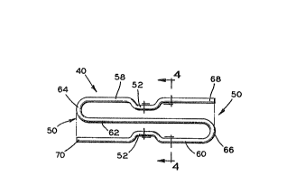
Referring again particularly to Fig. 3, each spring
pin is formed with a pair of opposed detents 52 as earlier
noted, each positioned intermediately of the ends 50 of
the elongated body of the spring pin 40. Each spring pin
defines a first leg 58 and a reversely extending second
leg 60, each leg containing one of the pair of detents.
An intermediate third leg 62 integrally joins the first
and second legs 58 and 60 ~ogether. Each end 50 defines a
bight portion 64 and 66, respectively. The bight 64 is
.' ' ' , .
. ~, . ,
~ ~ 7 ~
formed by the integral joinder of the first and
intermediate legs, while the bight 66 is formed by the
integral joinder of the second and intermediate legs.
Each end 50 thus defines a bight and a leg end 6B,70; the
left end 50 defining the afore-described bight 64 and the
end 70 of the second leg 60, while the right end 50
defines the bight 66 and the end 68 of the first leg 58.
In operation, those skilled in the art will appreciate
that whenever the cam contact surfaces 54 associated with
the spring pins 40 ride up out of the detents S2 of the
spring pins, the respective bights 64, 66 and leg end
portions 68, 70 of the pins will elastically move toward
each other. Upon movement of the surfaces 54 back into
the detents 52, the bights and leg ends will spring apart
and back to the normally unstressed position represented
in the drawing figures.
Finally, referring to Fig. 4 t it will be noted that
the cross sec~ion 72 of the spring pin 40 in the preferred
embodiment will have rounded corners defined by arcuate
edges 74 as shown. The present inventor has determined
that such edges were effective to avoid stress fracture
propogations which otherwise occurred and shortened the
fatigue life of the spring pin. In a preferred form, the
cross section approaches that of an oval shape, as
generally shown.
Although only one preferred embodiment has been
detailed and shown herein, the following claims are
envisioned to cover numerous other embodiments which fall
within the spirit and scope thereof.