Note: Descriptions are shown in the official language in which they were submitted.
B~CKGROUND OF THE INVENTION
The present invention relates to a microwave filter
composed of at least two cavity resonators in which energy is
propagated in at least one TE or TM mode, with a coupling
aperture provided between two adjacent cavity resonators
coupling together the two modes of the two cavity resonators.
Such a microwave filter is disclosed, for e~ample, in
U.S. Patent No. 3,697,898 and in IEEE TRANSACTIONS ON
MICROW~VE THEORY AND TECHNIQUES, Vol. MIT-32, No. 11,
November, 1984, pages 1449-1354. The resonant circuits of
the microwave filters forming the basis of these disclosures
are realized by TE and/or TM modes which oscillate in
resonance in the individual cavity resonators. The char-
acteristic of such a microwave filter depends on which
mutually orthogonally polarized modes exist in the individual
cavity resonators and which of these modes are coupled
together. There are couplings between the modes existing in
an individual cavity resonator and couplings between modes
in different cavity resonators. Mode couplings taking place
from cavity resonator to cavity resonator are effected by way
of coupling apertures equipped with coupling irises.
SUMMARY OF THE INVENTION
It is an object of the present invention to provide
a microwave filter of the above-mentioned type which offers
more possibilities for establishing selected filter char-
acteristics than was possible in the prior art.
- 2 -
71~;3~:
These and other objections are achieved, according to
the invention by a microwave filter composed of at least two
cavity resonators disposed adjacent one another, and means
including a coupling aperture disposed between the resona-
tors for coupling microwave energy between the resonators,one of the cavity resonators constituting means for
propagating microwave energy having a TE mode and the other
of the cavity resonators constituting means for propagating
microwave energy having a TM mode, wherein the means
including a coupling aperture are constructed for coupling
the TE mode in the one cavity resonator with the TM mode in
the other cavity resonator.
In the microwave filters disclosed in U.S. Patent
No. 3,697,898 and in IEEE TRANSACTIONS ON MICROWAVE THEORY
AND TECHNIQUES, couplings between cavity resonators are used
only between identical polarity TE modes and between identi-
cal polarity TM modes. A plurality of further filter
characteristics can be realized if, as in the present
application, TM modes in one cavity resonator are also
coupled to TE modes of another cavity resonator.
The invention will now be described in greater detail
with reference to an embodiment that is illustrated in the
drawing.
-- 3 --
` ~'71532
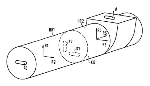
BRIEF DESCRIPTION OF THE DR~WING
Figure 1 is a perspective view of a microwave filter
according to the invention having two cavity resonators.
Figures 2a and 2b are diagrammatic views showing a
TM-Olp and a TE-lln mode, respectively.
DESCRIPTION OF TEE PREFERRED EMBODIMENTS
The microwave filter shown in Figure 1 is composed of
two cylindrical cavity resonators HRl and HR2 of which the
first cavity resonator H~l has an input aperture or iris E
for coupling in a microwave signal and the second cavity
resonator HR2 has an output aperture or iris A for coupling
out a signal. Known techniques for coupling microwave
signals in and out can be used and will not be discussed in
detail here.
The illustrated microwave filter ha~ a total of five
resonant circuits, or electrical cavities, Rl ... ~5, of
which resonant circuits Rl and ~2 are realiæed in first
cavity resonator HRl and resonant circuits R3 and R4 are
realized in second cavity resonator HR2 by TE-lln modes (n =
1, 2, 3, ...) which have the polarity directions indicated by
the associated arrows in Figure 1. The E-field lines of the
TE-lln mode shown in Figure 2b correspond to the direction of
polarization of that mode. The fifth resonant circuit R5 of
the filter is realized by a TM-Olp mode (p = O, 1, 2,
...) which is polarized orthogonally to the TE-lln modes.
The TM-Olp mode is shown in Figure 2a. Its E-field lines
-- 4 --
~; :7~32
extend in the direction of wave propagation, the polarization
direction (see arrow R5~ o~ this TM-Olp mode.
The orthogonally polarized modes existing in each
individual cavity resonator can be coupled by means of
discontinuity coupling members, e.g. tuning screws inserted
in the cavity wall in a known manner.
The modes of the one cavity resonator HRl are coupled
with the modes of the other cavity resonator HR2 by way of a
coupling aperture KB provided between the two adjacent cavity
resonators. Coupling aperture K~ also has an eccentric,
slit-shaped coupling iris Kl. This coupling iris is disposed
at a location where the magnetic field lines or components of
the TE-lln mode of resonant circuit Rl in the first cavity
resonator HRl and the magnetic field lines of the TM-Olp mode
of resonant circuit R5 in the second cavity resonator
HR2 are substantially parallel to one another. Thus, these
two modes are coupled with one another through the coupling
iris Kl. Moreover, the coupling iris K~ arranged in this
manner also couples the TE-lln mode of resonant circuit Rl of
the first cavity resonator HRl with the identically polarized
TE-lln mode of resonant circuit R4 in the second cavity
resonator HR2.
Similarly, the TE-lln mode of resonant circuit R2 in the
first cavity resonator HRl can be coupled with the TM-Olp
mode of resonant circuit R5 and also with the TE-lln mode of
resonant circuit R3 in second cavity resonator HR2 by way of
i532
27371-159
a fur-ther coupling iris K2 arranged eccentrically with respect to
coupling aperture KB and shifted by 90 with respect to coupling
iris K1. As indicated by the above statements, it is -thus poss-
ible to realize a large number of couplings be-tween different
types of modes, or more precisely between modes having different
polarities, of adjacent cavity resonators by means of a very
simple coupling iris structure.
The selected dimensions and position of the coupling
iris are determined by -the desired center frequency of the filter
and the desired coupling between the resonant circui-ts.
In the above-described embodiment, the microwave filter
is composed of only two cavity resonators. Of course it is also
possible to construct filters of more than just two cavity reson-
ators, in which case a single mode, dual mode or triple mode
exists in each individual cavity resonator, which are then coup-
led depending on the filter characteristic desired.
The first cavity resonator HRl has a diameter of 26 mm
and a length of 44.5 mm and the second cavity resonator HR2 has a
diameter of 22 mm and a length of 49 mm.
The input aperture E which is centered on -the front
side of the first cavity resonator HRl has a form of a slot
(length: 9.7 mm, width: 3 mm). The output
~ - 6 -
7~L~32
aperture A which has also a form of a slot (length: 10.5, width: 3 mm) is located
in the side wall of the second cavity resonator HR2. This output slot A extends in
the middle of the second cavity resonator HR2 orthogonally to the longitudinal axis
of resonator HR2.
The slit-shaped coupling irises Kl and K2 are dimensioned and eccentrically
located in the coupling aperture KB as follows:
Coupling iris Kl has a length of 4 mm and a width of 1.5 mm and coupling
iris K2 has a length of 7.1 mm and a width of 1.5 mm. Both coupling irises K1
and K2 are orthogonally oriented to one another whereby coupling iris K1 is dis-
placed for 4.75 mm from the center of the coupling aperture KB and coupling iris
K2 is displaced for 4 mm from the center of the coupling aperture KB.
- 6a -
;'
;3~:
27371-159
The invention now being fully described, it will be
apparent to one of ordinary skill in the art that many changes and
modifications can be made thereto without departing from the
spirit or SCOp2 of the invention as set forth herein.