Note: Descriptions are shown in the official language in which they were submitted.
12~17~9
SUSPEUSION LIQUID SEPARATOR
Background of the Invention:
This invention relates to liquid suspension
separators and, more particularly, to a liquid
suspension separator which will permit separation of the
5. suspension liquid from the suspended particulates.
At the present time, the separation of
particulates from sugpensory liquid as, for example, the
particulates from blood 4erum, entails the subjection of
the blood sample to laboratory procedureæ which are both
10. elaborate and expensive. Such procedures, of course,
cannot be utilized in field testing where tests on the
suspensory liquid are indicated.
For instance, it is well known that a large
percentage of slaughtered hogs are infected with
15. trichinosis and that many beef carcasses are infected
with various types of parasites such as worms and the
like. However, the testing of the carcasses to deter-
mine the presence of such infestations entails the
dissection of portions of the carcaases or the obtention
20. of blood samples from the individual carcasses and the
laboratory separation and te~ting of the samples.
. Present-day blood separation and testing
procedures require that the specimens be drawn from
individual carcasse~, transported to a laboratory for
~5. 4eparation and then ~ubjected to laboratory testing. As
~ 7~ ~
a matter of fact, such procedures have been Eollowed in
some countries, but the expense oiE such testing greatly
increases the ultimate cost oE the meat derived fro~n
the carcasses.
According to one aspect of my invention there
is provided a liquid suspension separator which can be
utilized in slaughterhouses or similar environments to
conduct blood separations resulting in liquid test
samples which can be immediately subjected to the
requisite test or assay to indicate the inEestation of
the carcass being subjected to the test.
It should be understood that, while the
application and utilization of the liquid suspension
separator is described herein in conjunction with tests
on carcasses and the like to determine the infestation
of the carcass by varous types of parasites, the liquid
suspension separator may be utilized in many applica-
tions, including emergencies which occur in connection
with injuries to human beings or in veterinary applica-
tions involving the treatinent of animals. In other
words, it is not intended that the application of the
teachings of the invention be limited solely to the
ascertainment oE the infestation in edible carcasses.
I also provide a separator oE the
aEorementioned character which includes a housing
incorporating a separator chamber. A nu~nber of ports
are provided by the housing in co~n~nunication with the
separator chamber including an eluant port, a liquid
~17~9
suspension port and a discharge port.
The eluant port is adapted to receive eluant
which is introduced into the separator chamber for a
purpose which will be described in greater detail below.
Of course, the liquid suspension port receives the
suspension, such as blood, for suitable separation in
the separator chamber.
In turn, the discharge port discharges the
liquid component of the suspension after the particu-
lates have been filtered therefrom in a manner to be
described in greater detail below.
The housing may be fabricated from a wide
variety of suitable materials which are impervious to
liquid flow including vinyl or polyethylene plastics or
the like. The housing may be formed by injection or
blow molding and is usually of sufEicient size to
receive the required eluant dosage and liquid
suspension adequate for the provision of a requisite
liquid test specimen.
Incorporated in the separator chamber is a
filter consisting of a body of filter material. The
body may be formed from any of a number of depth-type
planar filter materials capable of entrapping formed
suspension elements or particulate~s during eluant-
induced Elow between the filter surEaces. Exelnplary of
such a ~naterial is glass ~nicrofiber filter material
which is available in a range of porosities suitable for
entrapping formed elements or particulates from a number
j~:
~ 71~3
of suspensions such as blood and tissue washes.
An inherent characteristic oE the filter
material is that the filter porosities are intercon-
nected in the plane of the filter. A conventional
filter which is capable of entrapping formed suspension
elements or particul.ates but which is not suitable for
the practice of the invention`is a planar membrane
filter which has porositi.es connecting its opposite
surfaces but offers no pathway for lateral flow
generally parallel to and between the surfaces.
According to a :Eurther aspect of my invention
there is provlded a separator of the aforementioned
character in which the aforesaid filter body is disposed
in intimate contact with the adjacent walls of the
separator chamber in order that neither eluant nor fluid
suspension bypass the porosities of the filter. Such
bypassing would, in the case of the eluant, provide an
unduly diluted fluid test specimen and, in the case of
the suspension, permit the bypassing of particulates or
other suspended materials to the discharge port.
According to another aspect of my invention
there is provided a separator of the aforement;oned
character having receptor means incorporated i.n the
housing thereoE whereby a test or assly device ~llay ~)e
insertt^~d into juxt.li)osition t(:> the :Liql.t-id clischarge
port o:E the separator in order that an imlllediate test
may be accomplished~
A
~LX7~7[39
According to a still Eurther aspect of my
invention there is provided a separator of the aforemen-
tioned character in which the test or assay specimen is
incorporated in the housing of the separator immediately
adjacent to and in fluid communication with the dis-
charge port. With this embodiment of the invention an
immediate test can be achieved without the utilization
of an ancillary testing device.
Accordîng to yet another aspect of this
invention there is provided in a suspension liquid
separator, the combination of: a housing having a
separator chamber and an eluant port, a liquid
suspension receiving port and a liquid discharge port
communicating with said chamber; and a depth-type,
planar, liquid filter body located in said chamber in
juxtaposition to said ports, said filter body having
one portion adjacent said eluant and liquid suspension
receiving ports and another portion adjacent said
liquid discharge port and the porosities of the fil.ter
material being interconnected in the plane of the
filter, the width of
said chamber at said another portion being configured
such that said another portion completely fills said
chamber, whereby :El.uid El.-)w i.sl rest~i.cted wi.thin sai.d
:Eilter body.
According to a still further aspect of the
present invention there is provided in a liquid
~.~'7~ 3
suspension separator :Eor providing a liquid test
specimen from which particulates have been removed, the
combination of a housing incorporating a separator
chamber, said housing having eluant and liquid
suspension ports located at one extremity of said
chamber and a discharge port communicating with another
extremity of said chamber; a depth-type planar liquid
filter body located in said separator chamber in
juxtaposition to said ports, said filter body having
one portion adjacent said eluant and liquid suspension
receiving ports and another portion adjacent said
liquid discharge port, the width of said chamber at
said another portion being configured such that said
another portion completely fills said chamber, whereby
fluid flow is restricted within said filter body said
filter body incoporating laterally operative filtration
passages whereby eluant and liquid suspension
introduced into said chamber through said respective
ports will be conveyed to said discharge port while
said particulates are retained in said filter body.
Brief Description of the Drawings:
The invention will be more clearly understood
from the :Eollowing spec;fication and thc accolllpanyinc
drawings, which are Eor the purpose oE iLI.u.c;trat:i.on
only, in which:
P~
FIG. 1 is a front elevational view of a
separator constructed in accordance with the teachings
of the invention;
FIG. 2 i~ a rear elevational view;
5. FIG. 3 is a front elevational view of an
alternative embodiment of the invention;
FIG. 4 is a rear elevational view of the
embodiment of FIG. 3;
FIG. 5 is a vertical sectional view taken on
10. the broken line 5-5 of FIG. l;
FIG. 6 is a fragmentary, enlarged vertical
sectional view taken on the broken line 6-6 of FIG. 3;
FIG. 7 is an enlarged fragmentary sectional
view showing an alternative construction of the eluant
15. and suspension ports;
FIG. 8 is an enlarged fragmentary sectional
view showing an alternative embodiment of the eluant
reservoir of the separator;
FIG. 9 is a top plan view of a typical filter
20. body utilized in conjunction with the separator of the
invention;
FIG. 10 is a front elevational view of an
alternative embodiment of the separator of the
inventioh; and
25. FIG. 11 ~s a vertical sectional view taken on
the broken line 11-11 of FIG. 10.
A`` v~ .
~ ~ 7~ ~C3
Description of Preferred Embodiments of the Invention:
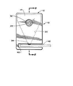
Referring to the drawings, and particularly to
FIGS. 1-2, 5 and 9 thereof, I show a liquid suspension
separator 10 which is incorpQrated in a substantially
5. rectangular housing 12 fabricated from any suitable
inert material such as vinyl or polyethylene plastics.
The housing 12, as best shown in FIG~ 5 of the
drawings, consists of a front se~tion 14 and a rear
section 16, said sections being joined at their abutting
10. surfaces 18 by means of a suitable adhesive. ~he front
and rear sections 14 and 16 of the housing are
configured to provide, in conjunction, a separator
chamber 20, as best shown in FIG. 5 of the drawings.
The separator chamber 20, as best shown in
15. FIG. 5 of the drawings, incorporates a filter 22
constituted by a filter body 24, said filter body being
illustrated in FIG. 9 of the drawings as being generally
of triangular configuration in plan.
The shape of the separator chamber is of the
20. same shape as the filter body 24 and the inner walls of
the chamber 20 are closely juxtapo~ed to the edges and
parallel suraces of the filter body to prevent
bypassing of eluant or the liquid suspension.
. As previously mentioned, the filter body 24 is
25. fabricated from any of a number of depth-type planar
i~, .,~
~7~7~)~
filter materials capable o entrappinq formed ~uspension
elements or particulates during flow between the
parallel surfaces of the filter contained in the
separator chamber 20. Illustrative of such filter
5. materials i~ a gla88 microfiber filter which is
available in a range of porosities suitable for
entrapping particulates from any number of su3pensions
of interest including blood and tissue washes.
As previously mentioned, it i9 absolutely
10. necessary that the porositie~ of the filter materials be
interconnected in the plane of the filter to facilitate
flow of the suspension and eluant from one end of the
filter to the other rather than between the eluant and
su~pension receiving ports.
15. The housing 12, a~ best shown in FIGS. 1-2
and 5 incorporates an eluant receiving port 30 which
permits a suitable eluant, such as a balanced salt
solution, to be introduced into the separator
chamber 20. Located in the front ~ection 14 of the
20. housing 12 is a suspension receivinq port 32 through
which the suspenslon, such a3 blood, may be introduced
to the separator chamber 20.
Located in juxtapo~ition to the lower
extremity of the filter body 24 is a liquid di~charge
25. port 34 whose dimQnsion may be of a ~ize requisite to
y
the desired rate of flow of the liquid component of the
su pension from the separator chamber 20.
It will be noted that the precise conformity
of the mass of the filter body 24 to the shape of the
5. separator chamber 20 is required in order that the
bypassing alluded to hereinabove be avoided and the
substantially triangular configuration of the filter
body 24 in separator chamber 20 has been chosen t~
achieve such conformity. In addition, the greater width
10. of the filter body 24 i8 located adjacent the eluant and
liquid suspension introductory ports 50 that the
relatively large quanity of liquid injected through
these ports may be adequately received by the filter
body 24 and conveyed through the gradually restricted
15. area of the filter body 24 to the inverted apex of the
generally triangular configuration of the filter
body 24.
Thus, the eluant introduced through the eluant
port 30 carries the introduced suspension through the
20. gradually restricted area of the filter body 24 and the
particulates are suspended in the interstice~ of the
filter body until the liquid component of the su~pension
is delivered to the discharge port 34.
It is al~o desirable to have the lower
25. extremity of the filter body 24 projecting through the
~.~
8~
discharge port 34 ~o that physical contact with the
relevant portion of a te~t or assay device may be
obtained.
By insuring physical contact between the lower
5. extremity of the filter body 24 and the relevant portion
of a test or assay device, the necessity for a substan-
tial flow of the liquid component of the suspension is
eliminated and, thu~, a large amount of eluant need not
be applied to the filer body 24 through the eluant
10. port 30.
The slot 40 may be provided in the lower
extremity of the hou~ing 12 to act as a guide for the
introduction of a test or assay device 42, a~ best shown
in FIG. 1 of the drawing~. The relevant portion of the
15. device 42 can be introduced into the slot 40 and the
filtered liquid component of the suspension be
contacted thereby to provide an immediate indication of
the desired chracteristic of the liquid component of the
suspension being ~ought.
20. Although I have dl~closed the utilization of a
glass microfiber filter and its incorpo'ration in the
separator chamber 20, there are other means available
for restricting the flow of eluant and the liquid
portion of the suspension to the body of the filter.
25. For instance~ the` filter body 24 can be sandwiched
~ 7~7~
between sheets of nonporous material parallel to and in
contact with the filter surfaces and edges. A typical
material for such enclosing sheet~ i8 sheets of vinyl
plastic which can be heat-sealed at the edges.
5. The enclosing sheets may ke pierced to provide
access to the eluant, suspension and discharge ports.
It was al50 conceivable that a filter utilizing the
sheets as the housing instead of the relatively rigid
housing formed from polyethylene might be utilized with
10. the ports provided in the sheets in the same manner as
in the more rigid housing.
An alternative embodiment of the invention is
disclosed at 50 in FIGS. 3, 4 and ~ of the drawings
wherein the same reference numerals as were utilized in
15. discussing identical components of the previously dis-
cu~sed embodiment are utilized.
The essential difference between the
previously discus3ed embodiment 10 an~ the present
embodiment 50 lies in the provision of a test chamber 52
20. in the lower extremity of the housing 12 in immediate
juxtaposition to and in fluid communication with the
discharge port 34. Located in the test chamber 52 will
be an assay or test composite 54 8Ui table for the test
being cqnducted. Therefore, the eluted liquid portion
25. of the suspension is transferred t~ the assay or test
~ 7~
chamber for immediate analysis. A viewing port 56 may
be provided in the wall of the test chamber 52 to permit
visual apperception of the test re~ults.
Although I have disclosed, in the previous
5. embodiments 10 and 50 of the invention simple injection
ports for the eluant and su~pension~, it is conceivable
that troughlike re~ervoirs 62 and 64 be provided adja-
cent the eluant and ~uspension ports 30 and 32, respec-
tively, see FIG. 7, ~o that the required dosage can be
10. placed in the troughlike reservoirs or receptacles 62
and 64 to permit the absorption of the eluant and
suspension into the fibrous interstices of the filter
body 24.
Alternatively~ as best illustrated in FIG. 8
15. of the drawings, a sealed capsule 72 can be provided
adjacent the eluant port 30 containing the requisite
amount of eluant previously determined to be necessary
to convey the liquid component of the su~pension to the
discharge port 34. The sealed capcule 72 incorporates a
20. rupturab~e area 74 which, when the cap~ule 72 is com-
pressed between the fingers, will ba ruptured to permit
the flow of eluant into the sep~rator chamber 20.
The separator of the invention may be utilized
to sepa~at~ a quantity of the liquid component of the
25. ~uspension by dosing the filter body 24 through the
suspen~ion port 32. The ~u~penslon enters the
i ~
7~
poro ities of the filter body 24 which permit liquid
flow but entrap the formed suspen~ion elements or
particulates.
A predetermined volume of eluant fed from the
5~ reservoir through the eluant port 30 displaces the
liquid portion of the suRpension from the suspension
port 32 toward the discharge port 34 in a path deter-
mined by the triangular configuration of the filter
body 24 and separator chamber 20. The volume of eluant
10. is selected so that the liquid portion of the suspension
will be displaced through the discharge port 34, while
the eluant is retained within the filter body 24.
A specific and particular exam~le of the use
of the separator of the invention i8 the obtaining of an
15. aliquot of the liquid portion of bovine blood for the
determination of parasitic infections in beef carcasses.
The separator is utili~ed in the ~laughterhouse to
obtain the blood sample and is attached to the beef
carcass during processing.
20. In usage, the blood samp~e is added at the
suspension port 32 and the formed blood elements or
particulates are trapped within the filter body 24 as
the eluant displaces the liquid portion of the blood
longitu~inally and laterally through the body of the
25. filter to the discharge port 34 where it is transferred
J~
~ 7~
to the test or assay strip or to such other object as
may be desired.
Another embodiment 80 of the separator of the
invention is ~hown in FIGS. 10 and 11 of the drawings.
5. The separator 80 include~ a generally rectangular
housing 82 which may be fabricated from the Bame types
of plastic as the previoucly discus~ed embodiments and
which includes an eluant reservoir 84 having an eluant
port 86 at the bottom thereof communicating with a
10. separator chamber 88 which is formed in the housing 82.
Located in the separator chamber 88 is a
filter body 90 which i6 of generally elongated
rectangular configuration, but which has a lower
truncated conical portion 92, as best shown in FIG. 10
15. of the drawings.
Formed in the wall of the housing in overlying
relationship with the filter bod~ 90 and below the
eluant port 86 is a suspension liquid port 94 which is
large enough to permit a sample of the suspension liquid
20. to be placed upon the filter body 90 and which i9
located below the eluant port 86 to permit the flow of
eluant from the eluant re~ervoir 84 to cause the
movement of the liquid component of the suspension
liquid~ downwardly by gravity toward the discharge
25. port 96.
,~ \, j
-~r
~-~7~7()~
As previously men'cioned~ the extreme lower end
of the filter body 90 may protrude through the discharge
port 96 into a slot 98 in the housin~ 82 to permit a
te~t assay to be inserted into contiguity to the lower
5. extremity of the filter body 90 and the discharge
port 96.
Of course, as previously mentioned, the
fabrication of the housings of the variou~ embodiments
can be accomplished in a wide variety of ways by the
10. utilization of an equally wide variety of manufacturing
expedients. For instance, the separator 80 may be
fabricated from an injection molded blank in which the
separator chamber is constituted by an elongated slot
for the reception of the filter body bhich slot is later
15. covered by a liquid-proof cover, such a~ a liquid-proof
label or the like.
Therefore, the expencive~ time-consuming and
impractical laboratory testing of beef blood samples is
eliminated and it becomes economically feasible by the
20. utilization of the separator manufactured in accordance
with thOe teachings of this invention to te~t individual
beef carcasses as they are transported along the line in
the slaughterhouse.
~ It will be apparent to those skilled in the
25. art that various e~bodiments other than those disclosed
hereinabove can be constr~cted which will fall within
the scope of the appended claim6, althou~h differing in
details of construction.
,.