Language selection

Search

Patent 1272072 Summary

Third-party information liability

Some of the information on this Web page has been provided by external sources. The Government of Canada is not responsible for the accuracy, reliability or currency of the information supplied by external sources. Users wishing to rely upon this information should consult directly with the source of the information. Content provided by external sources is not subject to official languages, privacy and accessibility requirements.

Claims and Abstract availability

Any discrepancies in the text and image of the Claims and Abstract are due to differing posting times. Text of the Claims and Abstract are posted:

  • At the time the application is open to public inspection;
  • At the time of issue of the patent (grant).
(12) Patent: (11) CA 1272072
(21) Application Number: 1272072
(54) English Title: WIND TURBINE OPERATED SAILBOAT
(54) French Title: VOILIER PROPULSE PAR TURBINE A AIR
Status: Expired and beyond the Period of Reversal
Bibliographic Data
Abstracts

English Abstract


ABSTRACT OF THE DISCLOSURE
The present invention provides a wind powered boat
comprising a vertical axis rotary turbine extending downwardly
to a water pump located within the boat. The boat is further
provided with a forwardly opening water inlet to and a
rearwardly opening water outlet from the pump, with the
turbine, when rotating, operating the pump to draw water
through the inlet and to force water out through the outlet for
propelling the boat.


Claims

Note: Claims are shown in the official language in which they were submitted.

THE EMBODIMENTS OF THE INVENTION IN WHICH AN EXCLUSIVE
PROPERTY OR PRIVILEGE IS CLAIMED ARE DEFINED AS FOLLOWS:
1. A wind powered boat comprising a vertical axis rotary
turbine having a shaft portion extending downwardly to a water
pump, said boat being further provided with a forwardly opening
water inlet to and a rearwardly opening water outlet from said
pump, said turbine, when rotating, operating said pump by said
shaft to draw in water through said inlet and to force same out
through said outlet for propelling said boat.
2. A boat as claimed in Claim 1 wherein turbine is
releasable from said pump.
3. A boat as claimed in Claim 1 including a rudder with a
water channel receiving and directing water flow from said
outlet for steering said boat.
4. A boat as claimed in Claim 1 wherein said pump
comprises a centrifugal pump.
5. A boat as claimed in Claim 1 wherein said outlet
comprises a venturi.

3502E 6805
6. A boat as claimed in Claim 1 having a catamaran
construction, said turbine being located generally centrally
thereof.
7. A boat as claimed in Claim 1 including braking means
for braking said turbine.
8. A boat as claimed in Claim 7 wherein said braking
means comprises an energy conversion device.
9. A boat as claimed in Claim 8 wherein said energy
conversion device comprises a heat generator.
10. A boat as claimed in Claim 9 including storage means
for storing heat energy from said heat generator.
11. A boat as claimed in Claim 7 including a fixed brake
portion and centrifugal force operated lever means connected to
a brake member which applies pressure at an increasing level on
said fixed brake portion with increasing centrifugal forces on
said lever means.
12. A boat as claimed in Claim 11 wherein said braking
means is housed in a heat storage tank.

Description

Note: Descriptions are shown in the official language in which they were submitted.


1;~'7~(~7~
FIELD OF THE INVENTION:
The present invention relates to a wind powered boat
and in particular to a boat powered by a wind operated vertical
5 axis rotary turbine.
BACKGROUND OF THE INVENTION:
In conventional sail boat construction the boat is
operated by a wind gathering sail which is most effective when
the boat is sailing down wind. However, when the boat has to
move up into the wind these typical sails are not nearly as
effective and require sailing expertise for moving the boat
through the water.
Some attempts have been made to take advantage of
different types of wind pick-up devices for use on sailing type
boats. For example, United States patent 4,061,105 issued
December 6th, 1977 to Garcia describes a wind powered boat
using a rotary sail device which rotates in the same direction
regardless of the wind direction. The power derived from the
sail device is then used to control a plurality of oars for
rowing the boat through the water.
~.

~ 7~ V~7~
1 3502E - 2 - 6805
From a practical standpoint the boat described above
in the Garcia patent is extremely cumbersome and quite complex
in its operation. Realistically it cannot be seen where an
extremely heavy and awkward arrangement incorporating a wind
mill operating rowing oars would be used by the average sailor.
SUMMARY OF THE PRESENT INVENTION:
The present invention provides a wind powered boat
which takes advantage of the most up-to-date technology without
suffering from undue complications and overly burdensome
structural components. More particularly the boat of the
present invention incorporates a vertical axis rotary turbine
which due to its technologically advanced construction is
extremely light in weight and simple yet efficent in its
operation. However, consistent with a vertical axis windmill
the turbine of the present invention rotates in the same
direction regardless of wind direction.
The wind powered boat of the present invention further
includes a shaft portion extending downwardly from the turbine
to a water pump with the boat being provided with a forwardly
opening inlet to and a rearwardly opening outlet from the water
pump. The operation of the entire arrangement is one in which

1~ 7~
1 3502E - 3 - 6805
the turbine when rotating operates the pump by the shaft to
draw in water through the inlet thereby creating a low pressure
area in front of the boat and to force the water out through
the outlet for propelling the boat.
BRIEF DISCUSSION OF THE DRAWINGS:
The above as well as other advantages and features of
the present invention will be described in greater detail
according to the preferred embodiments of the present invention
in which:
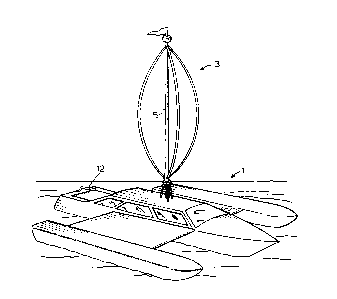
Figure 1 is a perspective view of a wind powered boat
according to a preferred embodiment of the present invention.
Figure 2 is a sectional view through the boat and
lower turbine region of the arrangement shown in figure 1.
Figure 3 is a perspective view of a brake or governing
device used for controlling speed of the turbine arrangement of
figures 1 and 2.
Figure 4 is a sectional view showing operation of the
braking or governing device of figure 3.

1i~7i~(~7~
1 3502E - 4 - 6805
DETAILED DESCRIPTION ACCORDING TO THE PREFERRED EMBODIMENTS OF
THE P~ESENT INVENTION:
Figure 1 shows a wind powered boat generally indicated
at 1 incorporating a vertical axis rotary turbine 3. This type
of turbine developed by a Frenchman, Darrius, with its
most-up-to-date construction includes a plurality of very small
lightweight vanes (usually two or three) which will rotate the
turbine regardless of wind direction and which has the
aerodynamic advantage that it will actually rotate faster than
the windspeed providing a very effective power source for the
boat. Furthermore because of the lightweight construction of
the Darrius type turbine it is easily positioned and supported
atop the boat.
In the preferred embodiment for use on a small craft
the actual boat itself has a catamaran construction giving
substantial width to the boat and providing a buffer to either
side of the turbine. In larger craft, such as ocean going
vessels, where the turbine is also particularly useful, the
craft will have more than enough width for required clearance
and will in many cases include a plurality of turbines for
powering the craft.

~ 7~ 07~
1 3502E - 5 - 6805
Figure 2 shows a center shaft 5 from the turbine which
extends downwardly through a housing 13 to a centrifugal water
pump 7. Water inlet 9 through the front of the boat to the
pump and water outlet 11 from the pump to the rear of the boat
are both located below water level in the boat.
lû The operation of the turbine for controlling the
centrifugal pump is extremely simple and efficent. More
particularly the turbine rotates regardless of wind direction
and through shaft 5 causes rotation of the impellor in the
centrifugal pump to draw water in through inlet 9 and to force
the water outwardly through outlet 11. This creates a low
pressure at the front of the boat from which the water is drawn
and provides a propelling stream of water through the back of
the boat to push the boat forwardly. It is to be noted that
outlet 11 is formed as venturi for increasing the flow velocity
2û through the outlet and adding to the propulsion of the outgoing
water stream.
The centrifugal pump itself other than its connection
with the wind operated turbine is of a standard pump
construction and therefore requires no further description.

1 3502E - 6 - 6805
As mentioned above the operation of wind turbine 3 is
extremely efficient. In fact it is efficent to the extent that
a governing or brake device is required to prevent over
rotation of the turbine. Such a device is shown in figures 3
and 4 and generally indicated at 15.
More particularly the braking device comprises a plate
17 fixed within the boat against rotation and fitted around
rotating shaft 5 with a drum like brake member 19 fitted over
plate 17. This brake member is connected through a pair of
cables 23 to centrifugally operated lever arms 25. For
mechanical advantage purposes the cables are fitted through
pullies 27 between the brake member and the lever arms which
are in turn mounted directly to shaft 5 through mounting collar
29.
The overall braking device is fitted within the
housing or storage chamber 13 as seen in figure 4 and operates
in the following manner.
The turbine rotates shaft 5 which in turn causes
rotation of the braking assembly. As the braking assembly
rotates the centrifugal forces acting on it cause levers 25 to
pivot upwardly thereby pulling on cables 23. The cables in
turn pull on drum brake 19 which includes a splined portion 19a

1~ 7~ ~7~
1 3502E - 7 - 6805
mating with splined portion 5a of shaft 5 which rotationally
couples the drum brake on the shaft but which also allows the
drum brake to climb vertically on the shaft.
The drum brake is further provided with an interior
brake pad 20 which with upward movement of the drum brake comes
into braking contact with the lower surface of plate 17. The
faster the shaft and lever arms rotate the greater the upward
pull on cables 23 resulting in increased friction directly on
the fixed plate. In other words the greater the tendency for
the turbine to rotate the greater the braking action so that
the braking assembly is in effect self adjusting and prevents
over rotation of the turbine.
The braking assembly is as mentioned above located
within a housing 13 which acts as a storage chamber for the
heat energy generated during braking. This heat energy can be
put to any desired use or additionally the arrangement could be
set up to produce different types of power such as electrical
energy which would also be put to different desired uses on the
boat.
In some cases it will be desired to allow rotation of
the turbine witho~t actually operating the centrifugal pump.
To this end shaft portion 5 is provided with a quick connect
disconnect coupler 31 as seen in figure 4 and located between

~7;~07~
1 3502E ~ 6805
the turbine and the pump. With the coupler in the connect
position the turbine will cause operation of the pump and with
the coupler in the disconnect position the turbine will rotate
without operating the pumpO
For steering purposes the boat is provided with a
rudder 12 as seen in figures 1 and 2. The rudder is used to
control direction of the boat and includes a water channel
which receives and redirects the flow from outlet 11 in the
direction of the rudder for steering the boat.
Although various preferred embodiments of the present
invention have been described herein in detail it will be
appreciated by those skilled in the art that variations may be
made thereto without departing from the spirit of the invention
or the scope of the appended claims.

Representative Drawing
A single figure which represents the drawing illustrating the invention.
Administrative Status

2024-08-01:As part of the Next Generation Patents (NGP) transition, the Canadian Patents Database (CPD) now contains a more detailed Event History, which replicates the Event Log of our new back-office solution.

Please note that "Inactive:" events refers to events no longer in use in our new back-office solution.

For a clearer understanding of the status of the application/patent presented on this page, the site Disclaimer , as well as the definitions for Patent , Event History , Maintenance Fee  and Payment History  should be consulted.

Event History

Description Date
Inactive: IPC expired 2020-01-01
Inactive: IPC from MCD 2006-03-11
Time Limit for Reversal Expired 2002-07-31
Letter Sent 2001-07-31
Inactive: Late MF processed 1999-11-26
Letter Sent 1999-08-03
Grant by Issuance 1990-07-31

Abandonment History

There is no abandonment history.

Fee History

Fee Type Anniversary Year Due Date Paid Date
MF (category 1, 7th anniv.) - small 1997-07-31 1997-07-28
MF (category 1, 8th anniv.) - small 1998-07-31 1998-07-15
MF (category 1, 9th anniv.) - small 1999-08-03 1999-11-26
Reversal of deemed expiry 1999-08-03 1999-11-26
MF (category 1, 10th anniv.) - small 2000-07-31 2000-07-26
Owners on Record

Note: Records showing the ownership history in alphabetical order.

Current Owners on Record
ROBERT HALL
Past Owners on Record
None
Past Owners that do not appear in the "Owners on Record" listing will appear in other documentation within the application.
Documents

To view selected files, please enter reCAPTCHA code :


To view images, click a link in the Document Description column. To download the documents, select one or more checkboxes in the first column and then click the "Download Selected in PDF format (Zip Archive)" or the "Download Selected as Single PDF" button.

List of published and non-published patent-specific documents on the CPD .

If you have any difficulty accessing content, you can call the Client Service Centre at 1-866-997-1936 or send them an e-mail at CIPO Client Service Centre.


Document
Description 
Date
(yyyy-mm-dd) 
Number of pages   Size of Image (KB) 
Cover Page 1993-10-08 1 11
Abstract 1993-10-08 1 10
Drawings 1993-10-08 2 50
Claims 1993-10-08 2 39
Descriptions 1993-10-08 8 178
Representative drawing 2001-10-15 1 11
Maintenance Fee Notice 1999-08-31 1 179
Late Payment Acknowledgement 1999-12-09 1 171
Maintenance Fee Notice 2001-08-28 1 179
Fees 1996-06-12 1 65
Fees 1995-07-05 1 63
Fees 1994-07-26 1 39
Fees 1993-07-22 1 30
Fees 1992-07-23 1 31