Sélection de la langue

Search

Sommaire du brevet 1272072 

Énoncé de désistement de responsabilité concernant l'information provenant de tiers

Une partie des informations de ce site Web a été fournie par des sources externes. Le gouvernement du Canada n'assume aucune responsabilité concernant la précision, l'actualité ou la fiabilité des informations fournies par les sources externes. Les utilisateurs qui désirent employer cette information devraient consulter directement la source des informations. Le contenu fourni par les sources externes n'est pas assujetti aux exigences sur les langues officielles, la protection des renseignements personnels et l'accessibilité.

Disponibilité de l'Abrégé et des Revendications

L'apparition de différences dans le texte et l'image des Revendications et de l'Abrégé dépend du moment auquel le document est publié. Les textes des Revendications et de l'Abrégé sont affichés :

  • lorsque la demande peut être examinée par le public;
  • lorsque le brevet est émis (délivrance).
(12) Brevet: (11) CA 1272072
(21) Numéro de la demande: 1272072
(54) Titre français: VOILIER PROPULSE PAR TURBINE A AIR
(54) Titre anglais: WIND TURBINE OPERATED SAILBOAT
Statut: Périmé et au-delà du délai pour l’annulation
Données bibliographiques
Abrégés

Abrégé anglais


ABSTRACT OF THE DISCLOSURE
The present invention provides a wind powered boat
comprising a vertical axis rotary turbine extending downwardly
to a water pump located within the boat. The boat is further
provided with a forwardly opening water inlet to and a
rearwardly opening water outlet from the pump, with the
turbine, when rotating, operating the pump to draw water
through the inlet and to force water out through the outlet for
propelling the boat.

Revendications

Note : Les revendications sont présentées dans la langue officielle dans laquelle elles ont été soumises.


THE EMBODIMENTS OF THE INVENTION IN WHICH AN EXCLUSIVE
PROPERTY OR PRIVILEGE IS CLAIMED ARE DEFINED AS FOLLOWS:
1. A wind powered boat comprising a vertical axis rotary
turbine having a shaft portion extending downwardly to a water
pump, said boat being further provided with a forwardly opening
water inlet to and a rearwardly opening water outlet from said
pump, said turbine, when rotating, operating said pump by said
shaft to draw in water through said inlet and to force same out
through said outlet for propelling said boat.
2. A boat as claimed in Claim 1 wherein turbine is
releasable from said pump.
3. A boat as claimed in Claim 1 including a rudder with a
water channel receiving and directing water flow from said
outlet for steering said boat.
4. A boat as claimed in Claim 1 wherein said pump
comprises a centrifugal pump.
5. A boat as claimed in Claim 1 wherein said outlet
comprises a venturi.

3502E 6805
6. A boat as claimed in Claim 1 having a catamaran
construction, said turbine being located generally centrally
thereof.
7. A boat as claimed in Claim 1 including braking means
for braking said turbine.
8. A boat as claimed in Claim 7 wherein said braking
means comprises an energy conversion device.
9. A boat as claimed in Claim 8 wherein said energy
conversion device comprises a heat generator.
10. A boat as claimed in Claim 9 including storage means
for storing heat energy from said heat generator.
11. A boat as claimed in Claim 7 including a fixed brake
portion and centrifugal force operated lever means connected to
a brake member which applies pressure at an increasing level on
said fixed brake portion with increasing centrifugal forces on
said lever means.
12. A boat as claimed in Claim 11 wherein said braking
means is housed in a heat storage tank.

Description

Note : Les descriptions sont présentées dans la langue officielle dans laquelle elles ont été soumises.

1;~'7~(~7~
FIELD OF THE INVENTION:
The present invention relates to a wind powered boat
and in particular to a boat powered by a wind operated vertical
5 axis rotary turbine.
BACKGROUND OF THE INVENTION:
In conventional sail boat construction the boat is
operated by a wind gathering sail which is most effective when
the boat is sailing down wind. However, when the boat has to
move up into the wind these typical sails are not nearly as
effective and require sailing expertise for moving the boat
through the water.
Some attempts have been made to take advantage of
different types of wind pick-up devices for use on sailing type
boats. For example, United States patent 4,061,105 issued
December 6th, 1977 to Garcia describes a wind powered boat
using a rotary sail device which rotates in the same direction
regardless of the wind direction. The power derived from the
sail device is then used to control a plurality of oars for
rowing the boat through the water.
~.

~ 7~ V~7~
1 3502E - 2 - 6805
From a practical standpoint the boat described above
in the Garcia patent is extremely cumbersome and quite complex
in its operation. Realistically it cannot be seen where an
extremely heavy and awkward arrangement incorporating a wind
mill operating rowing oars would be used by the average sailor.
SUMMARY OF THE PRESENT INVENTION:
The present invention provides a wind powered boat
which takes advantage of the most up-to-date technology without
suffering from undue complications and overly burdensome
structural components. More particularly the boat of the
present invention incorporates a vertical axis rotary turbine
which due to its technologically advanced construction is
extremely light in weight and simple yet efficent in its
operation. However, consistent with a vertical axis windmill
the turbine of the present invention rotates in the same
direction regardless of wind direction.
The wind powered boat of the present invention further
includes a shaft portion extending downwardly from the turbine
to a water pump with the boat being provided with a forwardly
opening inlet to and a rearwardly opening outlet from the water
pump. The operation of the entire arrangement is one in which

1~ 7~
1 3502E - 3 - 6805
the turbine when rotating operates the pump by the shaft to
draw in water through the inlet thereby creating a low pressure
area in front of the boat and to force the water out through
the outlet for propelling the boat.
BRIEF DISCUSSION OF THE DRAWINGS:
The above as well as other advantages and features of
the present invention will be described in greater detail
according to the preferred embodiments of the present invention
in which:
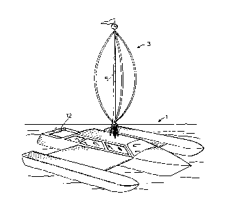
Figure 1 is a perspective view of a wind powered boat
according to a preferred embodiment of the present invention.
Figure 2 is a sectional view through the boat and
lower turbine region of the arrangement shown in figure 1.
Figure 3 is a perspective view of a brake or governing
device used for controlling speed of the turbine arrangement of
figures 1 and 2.
Figure 4 is a sectional view showing operation of the
braking or governing device of figure 3.

1i~7i~(~7~
1 3502E - 4 - 6805
DETAILED DESCRIPTION ACCORDING TO THE PREFERRED EMBODIMENTS OF
THE P~ESENT INVENTION:
Figure 1 shows a wind powered boat generally indicated
at 1 incorporating a vertical axis rotary turbine 3. This type
of turbine developed by a Frenchman, Darrius, with its
most-up-to-date construction includes a plurality of very small
lightweight vanes (usually two or three) which will rotate the
turbine regardless of wind direction and which has the
aerodynamic advantage that it will actually rotate faster than
the windspeed providing a very effective power source for the
boat. Furthermore because of the lightweight construction of
the Darrius type turbine it is easily positioned and supported
atop the boat.
In the preferred embodiment for use on a small craft
the actual boat itself has a catamaran construction giving
substantial width to the boat and providing a buffer to either
side of the turbine. In larger craft, such as ocean going
vessels, where the turbine is also particularly useful, the
craft will have more than enough width for required clearance
and will in many cases include a plurality of turbines for
powering the craft.

~ 7~ 07~
1 3502E - 5 - 6805
Figure 2 shows a center shaft 5 from the turbine which
extends downwardly through a housing 13 to a centrifugal water
pump 7. Water inlet 9 through the front of the boat to the
pump and water outlet 11 from the pump to the rear of the boat
are both located below water level in the boat.
lû The operation of the turbine for controlling the
centrifugal pump is extremely simple and efficent. More
particularly the turbine rotates regardless of wind direction
and through shaft 5 causes rotation of the impellor in the
centrifugal pump to draw water in through inlet 9 and to force
the water outwardly through outlet 11. This creates a low
pressure at the front of the boat from which the water is drawn
and provides a propelling stream of water through the back of
the boat to push the boat forwardly. It is to be noted that
outlet 11 is formed as venturi for increasing the flow velocity
2û through the outlet and adding to the propulsion of the outgoing
water stream.
The centrifugal pump itself other than its connection
with the wind operated turbine is of a standard pump
construction and therefore requires no further description.

1 3502E - 6 - 6805
As mentioned above the operation of wind turbine 3 is
extremely efficient. In fact it is efficent to the extent that
a governing or brake device is required to prevent over
rotation of the turbine. Such a device is shown in figures 3
and 4 and generally indicated at 15.
More particularly the braking device comprises a plate
17 fixed within the boat against rotation and fitted around
rotating shaft 5 with a drum like brake member 19 fitted over
plate 17. This brake member is connected through a pair of
cables 23 to centrifugally operated lever arms 25. For
mechanical advantage purposes the cables are fitted through
pullies 27 between the brake member and the lever arms which
are in turn mounted directly to shaft 5 through mounting collar
29.
The overall braking device is fitted within the
housing or storage chamber 13 as seen in figure 4 and operates
in the following manner.
The turbine rotates shaft 5 which in turn causes
rotation of the braking assembly. As the braking assembly
rotates the centrifugal forces acting on it cause levers 25 to
pivot upwardly thereby pulling on cables 23. The cables in
turn pull on drum brake 19 which includes a splined portion 19a

1~ 7~ ~7~
1 3502E - 7 - 6805
mating with splined portion 5a of shaft 5 which rotationally
couples the drum brake on the shaft but which also allows the
drum brake to climb vertically on the shaft.
The drum brake is further provided with an interior
brake pad 20 which with upward movement of the drum brake comes
into braking contact with the lower surface of plate 17. The
faster the shaft and lever arms rotate the greater the upward
pull on cables 23 resulting in increased friction directly on
the fixed plate. In other words the greater the tendency for
the turbine to rotate the greater the braking action so that
the braking assembly is in effect self adjusting and prevents
over rotation of the turbine.
The braking assembly is as mentioned above located
within a housing 13 which acts as a storage chamber for the
heat energy generated during braking. This heat energy can be
put to any desired use or additionally the arrangement could be
set up to produce different types of power such as electrical
energy which would also be put to different desired uses on the
boat.
In some cases it will be desired to allow rotation of
the turbine witho~t actually operating the centrifugal pump.
To this end shaft portion 5 is provided with a quick connect
disconnect coupler 31 as seen in figure 4 and located between

~7;~07~
1 3502E ~ 6805
the turbine and the pump. With the coupler in the connect
position the turbine will cause operation of the pump and with
the coupler in the disconnect position the turbine will rotate
without operating the pumpO
For steering purposes the boat is provided with a
rudder 12 as seen in figures 1 and 2. The rudder is used to
control direction of the boat and includes a water channel
which receives and redirects the flow from outlet 11 in the
direction of the rudder for steering the boat.
Although various preferred embodiments of the present
invention have been described herein in detail it will be
appreciated by those skilled in the art that variations may be
made thereto without departing from the spirit of the invention
or the scope of the appended claims.

Dessin représentatif
Une figure unique qui représente un dessin illustrant l'invention.
États administratifs

2024-08-01 : Dans le cadre de la transition vers les Brevets de nouvelle génération (BNG), la base de données sur les brevets canadiens (BDBC) contient désormais un Historique d'événement plus détaillé, qui reproduit le Journal des événements de notre nouvelle solution interne.

Veuillez noter que les événements débutant par « Inactive : » se réfèrent à des événements qui ne sont plus utilisés dans notre nouvelle solution interne.

Pour une meilleure compréhension de l'état de la demande ou brevet qui figure sur cette page, la rubrique Mise en garde , et les descriptions de Brevet , Historique d'événement , Taxes périodiques et Historique des paiements devraient être consultées.

Historique d'événement

Description Date
Inactive : CIB expirée 2020-01-01
Inactive : CIB de MCD 2006-03-11
Le délai pour l'annulation est expiré 2002-07-31
Lettre envoyée 2001-07-31
Inactive : TME en retard traitée 1999-11-26
Lettre envoyée 1999-08-03
Accordé par délivrance 1990-07-31

Historique d'abandonnement

Il n'y a pas d'historique d'abandonnement

Historique des taxes

Type de taxes Anniversaire Échéance Date payée
TM (catégorie 1, 7e anniv.) - petite 1997-07-31 1997-07-28
TM (catégorie 1, 8e anniv.) - petite 1998-07-31 1998-07-15
TM (catégorie 1, 9e anniv.) - petite 1999-08-03 1999-11-26
Annulation de la péremption réputée 1999-08-03 1999-11-26
TM (catégorie 1, 10e anniv.) - petite 2000-07-31 2000-07-26
Titulaires au dossier

Les titulaires actuels et antérieures au dossier sont affichés en ordre alphabétique.

Titulaires actuels au dossier
ROBERT HALL
Titulaires antérieures au dossier
S.O.
Les propriétaires antérieurs qui ne figurent pas dans la liste des « Propriétaires au dossier » apparaîtront dans d'autres documents au dossier.
Documents

Pour visionner les fichiers sélectionnés, entrer le code reCAPTCHA :


Pour visualiser une image, cliquer sur un lien dans la colonne description du document. Pour télécharger l'image (les images), cliquer l'une ou plusieurs cases à cocher dans la première colonne et ensuite cliquer sur le bouton "Télécharger sélection en format PDF (archive Zip)" ou le bouton "Télécharger sélection (en un fichier PDF fusionné)".

Liste des documents de brevet publiés et non publiés sur la BDBC .

Si vous avez des difficultés à accéder au contenu, veuillez communiquer avec le Centre de services à la clientèle au 1-866-997-1936, ou envoyer un courriel au Centre de service à la clientèle de l'OPIC.


Description du
Document 
Date
(aaaa-mm-jj) 
Nombre de pages   Taille de l'image (Ko) 
Page couverture 1993-10-08 1 11
Abrégé 1993-10-08 1 10
Dessins 1993-10-08 2 50
Revendications 1993-10-08 2 39
Description 1993-10-08 8 178
Dessin représentatif 2001-10-15 1 11
Avis concernant la taxe de maintien 1999-08-31 1 179
Quittance d'un paiement en retard 1999-12-09 1 171
Avis concernant la taxe de maintien 2001-08-28 1 179
Taxes 1996-06-12 1 65
Taxes 1995-07-05 1 63
Taxes 1994-07-26 1 39
Taxes 1993-07-22 1 30
Taxes 1992-07-23 1 31