Note: Descriptions are shown in the official language in which they were submitted.
~2~23>7~
TOY BUILDING BLOCK FOR CONSTRUCTION SET
`: :
Back~round of the Inventlon
The present invention relates to building blochs and in par-
ticular to toy building blocks for construction sets.
.
In European patent publication number 0,116,519 and U.S.
:patent 4,556,397 toy building blocks for construction sets
are disclosed. Such building blocks haYe side walls and a
wall extendlng~perpendicular thereto which is providea on ~:
one side with two rows of coupling pins and on the other side
wlth counter coupling sockets whl~ch cooperate wlth the coupl-
ing plns to provide a mechanical coupling or clamping effect
between two such blocXs. Every other coupling pin of each
row is provided with a conductive surface and the alternate
plns are electrically insulated. One row of pins is offset
with respect to the other row by one coupling pin in the
dlrect~ion~of the~rows~ A:contact bar lS mounted on the other
side of the wall along;ea;ch longitudinal sidewall and is in
:electrlcal contact with the conductive coupling pins of the
:corresponding row:and has a contac-t face for making electrical
contact with a row o~f conductive coupling pins of an adjacent
:: :
.
- :
' ~ ~ ~ ,' ` " ' ''
, . , ~ . , ,
. . .
~, ', : ~
:~L2~23~7~
21125-179
coupled block. During coupling of two such blocks a short
circui~-proof coupling of two separa~e circuits i~ possible in the
longitudinal direction or vertical thereto. However, if a model
is built by electrically coupling such prior art buildiny blocks
in more than two planes a problem arises ln ~hat the electrical
circuits may be shorted. This is particularly so when a loop is
formed during the construction of the model.
`~ It is an object of the present invention to provide a
bullding block of the aforementioned type with which an absolute
short circuit-proof coupling of two electrically separated
conductors may be attained even if a large number of such blocks
are coupled to each other and even if electrical loops are formed.
Surprisingly, with the building blocks of the present
invention short circuits eannot be caused between the two
`~; alectrical conductors even if the coupling pins of the building
blocks cross in a zig-zag arrangement or a structure is formed of
a large number of such blocks. As a result, the present building
blocks permit even an inexperienced user or a child to form
electrical circuits without problem.
Accordingly, the invention herein comprises a building
block for a toy construction set comprising: a top wall having an
outer sur~ace and an inner surface; a side wall extending from
said top wall; a plurality of coupling plns on the outer surface
of said top wall; said coupling pins each having electrically
conductive maans and said pins being arranged in at least two
equally spaced rows forming at least two equally spaced columns of
pins, the rows and columns being orthogonally directed; means for
:j
,,*., ~,
'; ~ ~
. .
.,~ , . .
,
~,:' ' ,'
: , .
- . : : . :
~2~2~
2112~-179
electrically connecting alternate coupling pin conductive means of
one row with alternate coupling pin conductive means of an
adjacent row whereby no coupling pin is electrically connected to
the coupling pin in neither the immediately adjacent row, nor the
immediately ad~acent column, thereby forming two separate
electrical conductors; and counter coupling means for engaging
pins of another block, said counter coupling means being on said
top wall inner sur~ace and including said side wall.
An exe~plified embodiment oE the building blocks of the
present invention along with a method of making ~he same is
explained in more detail forthwith in conjunction with the
drawings which illustrate the ~ollowing:
.
: .
:,
:
:' ~
, : :
2a
~ ' .
:. ~ , ' ' :
y~
Brief Description of the Drawin~s:
,
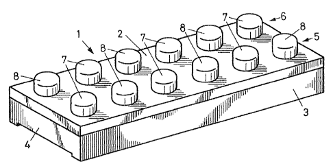
Fig. l is a perspective view of a building block in accord-
ance with the present invention;
Figs. 2 to Fig. 5 are perspective views oE the individual
components of the building block of Fig. l, set
forth in the sequence of assembly;
Fig. 6 is a plan view of the underside of the upper cover
plate depicted in F1g. 2;
Fig. 7 is a longitudinal sectional view taken long line
VII-VII of Fig. 6;
Fig. 8 is a cross sectional view taken along line VII-VII
of Fig. 6;
Fig~. 9 ;is a top;~plan v1ew~of the~lower support part de-
picte~d~1n Fig.~S
Fig ~10~ is a v1ew of the~bottom side of the lower part
dep~icted in~F1g.~S;~
Fig.~ll is a longitud1nal sectional view taken along line
XI-XI in Fig. 9; and
F1g~.~12~ 15 a cro~s sect1ona1 view taken along line XI1-XII
of~Fig~. 9. ~ ~ ~
etailed Descr1ption of the Preferred Embodiment
Referr;ing~`to Fig~ t can~be~seen that the outer shape and
dimensions of the present building block are quite similar
::
:'' . . . .. : ' ',
:: ~ . . ~ . -
': ,` . ' ,,.' :,, ' ' ` ' '
' ' ` ,: , ~,
, . : . .
: :: '
7~
-- 4 --
to building blocks which have been available for some time
under the registered -trademark "LEGO". Thus, the building
block consists of a general]y rectangular plastic body 1
which is open on its underside. The building block has a
top wall 2, long sidewalls 3 and short sidewalls 4. The top
wall is provided with two parallel rows 5, 6 of cylindrical
coupling pins 7, 8 arranged side-by-side which permit me-
chanical coupling in a conventional manner with sockets
within the hollow underside of a similar building block by
plugging the one into the other. The building block of
Fig. 1 differs from prior art blocks, however, in that each
of the coupling pins 7, 8 has a conductive metallic surface
encompassing at least the outer face of the coupling pins.
~: :
~ ~ .
As~wlll be explained~in more detall, the coupling pins are
connected with each other in two groups in such a manner
that all of the coupllng plns 7 form~a first electrical
conductor~and all of the coupling pins 8 form a second elec-
trical conductor.~The~ connection of the coupling pins is
effected through the use of two zig-zag members inserted
:
within the buildlng block.~ The coupling pins of each member
`~ ~ are displaced with respect to those of the other by the
longitudlnal distance between two adjacent coupling pins.
: -
~ ; The components of the building block of Fig. 1 are set forth
~; :
individually in sequence in Figs. 2 to 5 in the order of
assembly~ Thus, in Fig. 5 the bottom structural part is
:
.
: .:
: . , , . ' ' . ,
' ' " ~: : ' ' '
'
- . ~
, ~ :
~72~
depicted comprising a generally rectangular support part 9.
Support part 9, which is formed of plastic is hollow (al-
though this cannot be seen). The top surface 10 of support
part 9 is provided with a plurality of openings, recesses,
and protrusions including:
- two rows of slotted openings ll disposed along and ad-
jacent to the longitudinal sidewalls 3. The slots are
~ aligned in the longitudinal direction of the coupling
-~ pins 7, 8 of Fig. 1;
- round holes 12 positioned between adjacent slots 11 and
also including two disposed along the center line of
~` support part 9 close to the short walls 4;
rectangular recesses 13 disposed at an angle of 45 with
respect to the slots 11 and generally positioned along
the center line of support part 9 between the rows of
slots, the alternate recesses being displaced by about
90 with respect to each other. Each of the recesses 13
is provided at its center along its longitudinal edges
with a pnir of protrusions 14.
~: :
~:
~ ~ The function of the aforementioned openings, recesses and
: .
protrusions will become apparent from the following descrip-
tion of the other structural parts of the building block of
Fig. 1.
,
.
"
.
. .
3 27;~3
In Fig. 3 and 4 there are depicted tape-like members 15 and
16 containing the coupling plns or cylinders 7 and 8, respec-
tively. The coupling pins 7, 8 comprise hollow cylinders ar-
ranged in zig-~ag fashion along tapes 15 and 16, respec-
tively. Thus, coupling pins 7 are connected to each other
by the tape-like conductor segment 17 (Fig. 3) and coupling
pins 8 are connected to each other by the tape-like conduc-
: :
tor 18 ~Fig. 4). As can be seen, the conductor segments 17
of Fig. 3 are bent downwardly. A downwardly directed prong
~ . .
19 having an elongated tip is provided at the underside ofeach of the coupling pins 7, 8. The width of each prong 19
corresponds to the length of the slots 11 of support part 9.
The length of each prong 19 is somewhat less than the height
of the longitudinal s1dewalls 3 of support part 9. It should
be apparent that the entire tapes 15, 16 may each be formed
of a single piece of metal tape.
A~fourth structural part ls~depicted~in Fig. 2~and com- ~
prlses a plate-like, relatively thln cover 20 for the build-
ing block. Cover 20 is formed of plastic and comprises a
rectangu1ar~shape havlng~the same~dimensions as support
part 9. Cover 20 is~ provided with holes~21 through which
the~coupling plns 7, ;a pass. The underside of the cover 20
is provided with elongated pins 22 having a thickness gener-
ally corresponding to the diameter of holes 12 of part 9
and aligned with the holes. The end of each of the pins 22
;` : :
is conical.
-
'
:
~2~7237g
-- 7
Reference is now made to Fig. 6 which depicts the undersideof the cover part 20 and to Figs. 7 and 8 which are sectional
views thereof. Thus, the holes 21 for the coupling pins 7
and 8 can be se~n in Fig. 6 and the elongated pins 22 can
be seen in Figs. 6 to 8. Fig. 6 also shows that the cover
part 20 is provided with elongated rectangular recesses pro-
vlded on its underside along the center line of the cover
part which are disposed at an angle of 45 between adjacent
holes 21 of the same row and on the~diagonal with respect
to the two longitudinal rows of holes. In addltion, it can
be seen that the recesses are alternately displaced with
respect to each other by 90. Protrusions 24 are provided
in pairs along the longitudinal edges of each of the re-
cesses 23.
Detalls of the support part 9 can be seen ln Figs. 9 to 12.
Flg~ 9~illustrate~s the~top~of the~support part 9. Flg. lO
depicts the underside of the top. Referring to Fig. 9 the
~; :
slots ~11 for prongs 19 of the metaIlic strips 15 and 16~can
be seen~as well as the holes 12 for the cover part pins 22
and~the~recesses 13. Flg. lO also illustrates the slots ll
and the;holes~l2.~In addltlon,~Fig. 10 shows that the under-
side~of support;part 9 is~provided with elongated sockets 25
which serve as mechanical counter-coupling members for the
coupling pins 7, 8 when~two simllar blocks are plugged to-
gether. The sockets 25 as well as the recesses 13 and pro-
trusions 14 are~ also shown, ln section, in Figs. 11 and 12.
: ' ~ .' ' ' ' -
. : ' . .
.
~IL272;~79
Thus, Figs. 6 and 9 show that the top of support part 9
as well as the underside of cover part 20 are provided with
similar rectangular recesses 13 or 23, respectively, and
pairs of protrusions 14 or 24, respectively in correspond-
ing locations. It should be noted, however that the angular
orientation of the recesses 13 and 23 are displaced by 90.
This will become apparent when it is realized that the under-
side of the cover part 20 (Fig. 6) is to be mounted on the
top of support part 9 ~Fig. 9).
For a further understanding of the building block of the -~
present invention the assembly of the four components of
the block will now be discussed. The components comprise:
the support part S (Fig. 5); the metallic tapes 15 and 16
with coupl1ng pins 7 and:8, respect1vely, (Figs. 3 and 4);
and the~:cover part 20.
In the~first ~as;sembly step the prongs 19 of the metallic
tape 16:(which contains cbupllng pins a) are inserted into
the slots 11 of the support part 9 and the tape 16 is
pressed:into position on`the top of the support part 9.
As a result the downwardly bent conductor segments 18 of
~ ~: : : :
the conductor:tape 16 seat in the recesses 13 of the sup-
port part 9. The prongs 19 of the metallic tape lS (which
: contains coupling~pins 7) are~then inserted into the re-
maining slots 11 of the support part 9 and the tape 15 is
' ~ :
.
. .
: : . .
~27X~,~
then pressed into position. Since the conductor segments of
tape 15 are bent upwardly they will rest on the protrusions
14 and thus are physically as well as electrically spaced
apart and separated from the conductor segments 18 of tape
16. In the final assembly step the cover part 20 (Fig. 2)
is mounted over the partlal assembly with the coupling pins
7, 8 passing through the holes 21 of the cover part and the
pins 22 of the cover part being inserted into the holes 12
of the support part 9 whlch is facilitated by the conical
shape of the ends of pins 22. The pins 22 are then ultra~
sonically or thermally anchored in position. Since ultra-
sound energy may be applied to the unit to aid .in introduc-
ing the pins 22 into holes 12, this energy may also be used
to weld;the pins in position. Alternatively the pins 22~may
first be introduced into the~holes 12 and thereafter the ex-
posed ends of the pins 22 which protrude through~the top
fa=e~of~the support~p~r~9 are heat welded
As stated, when the cover part 20 lS mounted on the support
part~9 the upwardly bent conduotor segments 17 of tape lS
are dlsposed ln~the recesses;23 of the cover part 20 whlle
the conductor segments~18~;of tàpe 16 are supported on the
protrusions 24 of the c~over part. Thus, each of the conduc-
tor ségments 17~, 18 lS retalned by corresponding protrusions
14 or 24 adjacent the recesses 23 or 13. This insures that
a sufficLent electrLcal separation will be maintained between
,
.
.
.
:. , :, ' -
:~' : ' : ' .
'
~z~
-- 10 --
the conductor segments without requiring the use of any
additional insulating member.
It should be apparent that the relatively easy assembly of
only four components as described above may readily be
automated and practiced at high speed.
As can be seen from Figs. 3 and 4 the prongs 19 o~ the me-
tallic tapes 15 and 16 terminate in curved ends. When the
building block is assembled, the curved ends engage the
inner sides of the longitudinal sidewalls 3 of the support
part 3. The prongs 19 are formed of a yielding metal and,
as a result, when a block is pugged into another similar
block an electrical contact is made between the coupling
pins 7, 8 of the one~block and the prongs l9;of the other
block.~ In addltion, by dlmensloning the bullding~block;l,
including the coupling pins 7,~8~and the counter coupling
sockets 25 to conform to thoseof a conventional building
block~(such as~the previously mentioned LEGO~ building
block)~the building block 1 can be mechanically coupled
to~a conventional block~
Ihe~b~;ldl~g blr-k 1 h~s~two ~epa~a~e elec~rical circults
contained~therein one defined by the metallic strap 15 and
the other by the metallic strap 16. If a number of building
blocks l are coupled to one another the two clrcuits will
:, :
:'
~'
'. '.' '` ~ ' , "
~'
:':
: ' `: . .: .
1;~7X;~7~
- 11 -
always stay separated and short circuiting between the two
is prevented as long as at least two conductive coupling
pins of the one building block are coupled to two sockets
: of the other. This is true regardless of the complexity
~ of the model formed with the blocks.
:
~` : While the above invention has been described with coupling
:~ : pins;and sockets, it should be appreciated that other coupl-
: ing members could also be used, such as pins and sockets
having different geometric shapes such as for example, a
:
: square cross section.
~,; ,
:
,
'' "'
.
.
.
' ' ' ' ' ' ~ ' '