Note: Descriptions are shown in the official language in which they were submitted.
~2t7;;~
--1--
FEMORAL TRIAL PROSTFIESIS/~ASP ASSEr~L'~
This inven~ion relates to an instrument for
preparing the proximal femur to receive a proximal femoral
prosthesis. The instrument is a combination of a novel
handle assembly for securely holdiny a trial prosthesis/rasp
which is used to prepare the femur. The handle assembly is
then removed leaving the trial prosthesis/rasp in the femur
to accomplish trial reduction of the hip joint.
During hip surgery involving the replacement of the
proximal femoral head using a proximal femoral prosthesis,
the proximal femur must be prepared to receive the stem of
the proximal femoral prosthesis. A number of techniques have
been developed to accomplish the insertion of such
prostheses, and such techniques typically involve the use of
a rasp to accomplish the shaping of the proximal femur. Some
techniques employ a rasp attached to a handle which is only
used to prepare a socket in the proximal femur. A separate
trial prosthesis is then inserted in the socket to accomplish
reduction (i.e., proper sizing of a permanent femoral
implant).
To achieve the best fixation of the permanent
femoral implant, it has become a common practice to employ a
combination femoral trial prosthesis/rasp to prepare the
socket. The trial prosthesis/rasp is then left in the socket
and a femoral prosthesis head is placed on a post extending
from the trial prosthesis/rasp to accomplish reduction. The
post may also be used to assist in preparation of the calcar
surface. The trial prosthesis/rasp is then re~oved and a
permanent femoral prosthesis is inserted into the prepared
socket which remains basically unchanged since the rasping
procedure was completed.
~1~
` `'`' .
. , . .:: - . .
; : .. . . , . ~
,,
--2--
A number of instruments to hold the trial
prosthesis/rasp have been suggested. It is important that
the trial prosthesis/rasp be held rigidly. U.S. Patent Mo.
4,306,550 to Forte (lssued December 22, 1981~ shows a handle
containing a releasable chuck to engage the post on the trial
prosthesis/rasp. Other instruments using handles with chuc~s
to hold the trial prosthesis/rasp are shown on payes 19-23 of
a brochure entitled "The Total System" from Zimmer U.S.A.,
Inc. of Warsaw, IN and in item 16 (~rt. Nr. 5104) in a
Brochure entitled "Trunnion-head total hip, operative
technique" from ALLO PRO AG, Dorfstrasse 13, CH-6340
Baar/Zug. These chuck-type instruments are somewhat
complicated to manufacture.
As part of "The PCA~ Total Hip System", the
Orthopaedics Division of Howmedica, Inc. of Rutherford, N.J.
sells a Broach/Trial Stem Handle (Catalog No. 6079-0-000) for
use with Broach/Trial Stems (Catalog Nos. 6079-0-001 to -007
and 6080-0-001 to -007) wherein the Handle receives the
trunnion (post) on the Stem within a coupler which is closed
by means of a moveable arm and held shut by moving the arm
against the handle forming the main body. The coupler al~o
has a pin extending from its end which appears to engage with
the llpper part of the Stem on which the part is located.
Howmedica, Inc. also sells a Femoral Stem Extractor (Catalog
No. 6079-6-400) which appears to be a locking set of pliers
which is used to extract a femoral prosthesis stem from the
femur, but does not appear to be useful for inserting a
femoral trial prosthesis/rasp. These Howmedica devices are
described on pages 8, 14-17, and 43 of their brochure number
H4139 15M 1/84 B and on pages 42-49 of the surgical procedure
(FIGS. 38a - 44) found between pages 38 and 39 of that
brochure.
" ,:
. . , , :., - -:
:~
: .
. ~
--3--
Instruments employing screw-lock or push-pin
mechanisms to affix the trial prosthesis-rasp to the handle
are shown in brochure noO Y-BMT-010/U90183 entitled "CFE
TAPERLOC Hip System Surgical Technique" from ~iomet, Inc. of
l~arsaw, IN (spring-loaded button), and in brochure no.
20Ml183 0611-52 entitled "the AML~ Total Hip System with
Porocoat~" as Broach Handle 2002-22 from DePuy, Inc. of
Warsaw, IN (screw-lock). A femoral trial prosthesis andr
prosthesis Introducer/Extractor (Catalog No. JA 101)
employing a locking pin which passes through the handle and
the prosthesis is shown on page 90 (pages 43 and 44 show its
use) of a brochure entitled "The Poro Metal cementless total
hip prosthesis" distributed by Daumer International, P.O. Box
2229, 5632 Wermelskirchen, West Germany (page 91 shows a
Catalog No. JA 601 reamer which is not detachable or useful
as a trial prosthesis).
U.S. Patent No. 3,818,514 to Clark (issued June ~5,
1974) shows a protective sheath for a femoral prosthesis head
which employs a sheath lined with a compressible material
which fits about the prosthesis neck and possibly the head to
securely engage the prosthesis and to aid in the insertion of
the prosthesis into a prepared socket in the proximal femur.
The compressible material prevents damage to the head when
the prosthesis is pounded into the socket, but does allow the
prosthesis to move relative to the sheath.
There is still a need for an instrument which will
hold a femoral trial prosthesis/rasp rigidly in place during
use, but which permits simple engagement and disengagement of
the trial prosthesis/rasp.
It is one object of this invention to provide a
proximal femoral trial prosthesis/rasp assembly for use in
hip implant surgery. The novel handle assembly is easy to
use, but is very effective in rigidly grasping the trial
., , : ., :, :.
: : : :,.~ :
--4--
prosthesis/rasp while it is being used or removed frorn the
prepared bone socket.
The novel handle assembly grips the trial
prosthesis/rasp in a secure manner by clamping over and
locking onto a post located on the upper end of the trial
prosthesis/rasp. The handle assembly preferably comprises a
straight member which has a recess on its lower end for
reception of one half of the post in locking engagement and a
pivotable lever attached to the straight member which
contains an opposing recess which fits over the remainder of
the post when a screw located in the upper end of the lever
is tightened to bring the two lower ends of the handle
together over the post. By turning the screw, the lower ends
of the straight member and the lever are forced together and
the trial prosthesis/rasp is rigidly affixed to the handle
assembly in a rigid, but positive, manner. Preferably, the
lower end of the handle assembly is designed to cooperativelY
engage the upper end of the trial prosthesis/rasp at a
location separated from the post to further lend rigidity to
the entire trial prosthesis/rasp assembly.
Upon completion of the preparation of the bone
socket, the trial prosthesis/rasp is left in the femur and
the handle is disengaged from the post simply by turning the
screw. A trial reduction is then performed using the
embedded trial prosthesis/rasp. Preferably, the post is
adapted to receive a femoral prosthesis head for
accomplishing the trial reduction. When the redustion is
complete, the handle is reattached to the post and the
femoral trial prosthesis/rasp is removed from the bone socket
to permit fixation of a permanent proximal femoral prosthesis
to the femur in the prepared bone socket.
The above and other objects, features and
advantages of the present invention will become apparent to
.: . ;. : - , " ~
, ,~ . : . . :
:, ... .
--5--
those skilled in the art upon an examination of the following
description and drawings.
The present invention, therefore, provldes a
a femoral trial prosthesis/rasp assembly for use in the
implantation of a proximal femoral prosthesis, said assembly
comprising:
a trial prosthesis/rasp comprising a first
elongated member having a tapered and slightly curved
configuration extending from a relatively wide upper end
towards a narrower lower end, said member having a cutting
portion extending from said upper end downward over at least
a portion of its surface and having cutting teeth projecting
from the surface of said cutting portion, said first member
further having a post affixed to said upper end, and
a handle assembly adapted to releasably engage said
post and said upper end of the first member in a
predetermined orientation with respect to said handle
assembly, said handle assembly comprising:
a second elongated member having a lower end which
contains a recess adapted to receive a portion of said post
in close-fitting and locking engagement, said post having a
configuration which permits said locking engagement, said
second member having an upper end which is adapted to be
manually engaged and to be struck by a hammer to facilitate
use of the trial prosthesis/rasp to form a pros~hesis socket
in the femur,
a lever having a lower end which contains a recess
adapted to receive a portion of the post which is opposite
that which is engaged by ~he recess in the second elongated
member, a second opposlng end, and
a pivot pin means interconnecting said lever and
said second member at a point between the ends thereof
whereby the post is received and rigidly engaged within said
: . , ,., . .:
,
.
72~2~
-5a-
recesses when the lower end of said lever is biased in the
direction of the lower end of the second member by
a screw means which cooperatively engages and
passes through the upper end of said lever and is adapted to
bias said upper end of the lever away from the upper end of
the second member and cause the opposing lower ends of the
lever and second member to close and engage said post when
the screw means is turned in one direction and to permit sai~
lower ends to open and release said post when the screw means
is turned in the opposite direction.
In the Drawingso
FIG. 1 is an exploded view of the novel handle
assembly of the present invention.
FIG. 2 is a side view of lever 302 taken along line
2-2.
FIG. 3 is a view of the lower end of lever 302
taken along line 3-3.
FIG. 4 is a side view of member 102 taken along
line 4-4.
FIG. 5 is a view of the lower end of member 102
taken along line 5-5.
FIG. 6 is a plan view taken from the side of the
trial prosthesis/rasp assembly of the present invention which
comprises trial prosthesis/rasp 602 locked in handle assembly
100 .
FI~. 7 is a partial side view of assembly of FIG. 6
taken along line 7-7.
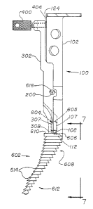
Referring now to the drawings, FIG. 1 depicts a
preferred form of the handle assembly 100 which is shown in
exploded form and comprises an elongated member 102 having a
lower end 104 containing a recess 106 wherein portion 107 of
recess 106 is deeper than portion 108 to permit a close-
fitting and locking engagement with one-half o~ post 604 as
shown in FIG. ~. Sur~ace 110 of end 104 is angled and thus
'1irregular" (i.e., not planar and perpendicular to the
central long axis of member 102) to enable it to mate with
i.. ~..
- : .,-,; . .,
.
. . : - .. , - : .
: ' ' : ' :;` :
- ~z~
-5b-
surface 610 of trial prosthesis/rasp 602 and retain trial
prosthesis/rasp 602 in a preselected orientation with respect
to handle assembly 100. Projection 112 ex~tends away from
surface 110 and is adapted to closely fit within recess 700
in trial prosthesis/rasp 602 to further lend rigidity to the
, ~
.
` ,~ J
' ~
,
:.' - ` ' ' . '' ~ i' '
:' ' : ` '' ' '' ' : :
:; ' ' ', , ~, ,...... ', ',, :
~7~
--6--
trial prosthesis/rasp 602 when it is engaged by handle
assembly 100.
The upper end 114 of member 102 is of sufficient
length to be manually engaged and can contain optional angled
holes 116 and 118 to provide a means to extrac* the trial
prosthesis/rasp assembly from the femur by placing a
conventional "tommy bar" (not shown) through holes 116 or 118
and pulling on the bar as a handle. Holes 116 and 118 are
placed at an angle (e.g., typically 15) with respect to the
prosthesis to be inserted so that the "tommy bar" can be used
as an alignment guide to assist the surgeon in preparing the
bone socket in accordance with well known surgical procedures
for femoral rasps. ~ne hole is angled for use on the left
femur and the o~her is angled for use on the right femur.
The top of upper end 114 contains plate 120 which
provides a surface on handle assembly 100 which can be struck
by a hammer during surgery. Member 102 further contains a
bore 122 located between ends 104 and 114. A small portion
121, 123 of member 102 in the vicinity of bore 122 is wider
than the remainder of member 102 to facilitate pivoting of
lever 302 relative to member 102.
Pin 200 is passed through bores 322, 122 and 323 to
pivotally interconnect lever 302 with member 102. The
diameter of pin 200 is slightly larger than the diameter of
bores 322 and 323 and is slightly smaller than the diameter
of bore 122 (or vice-versa) to permit pin 200 to be retained
within the bores and to allow lever 302 to pivot relative to
member 102. Pin 200 could also be a bolt or screw which is
passed through bores 322, 122, and 323 and fixed within the
bores by means of a locknut.
Lever 302 has a lower end 304 containing a recess
306 which is directly opposite to and corresponds with recess
106 when ends 304 and 104 are pivotally biased together.
~ . . - : ;. . ~ :
,
. :: ~ .: . .
` : ;: - .: . ',., . . .,.,., ` ;
-7-
Recess 306 is composed of portion 307 which is deeper than
portion 308 to permit a close-fitting and locking engagement
with the other half of post 604. The recess need not engage
the entire surface of the post as long as the post can be
lockingly engaged within the recesses.
In FIG. 6, post 604 is shown in the preferred
generally cylindrical configuration and, more preferably,
portlon 605 is adapted to receive a femoral prosthesis head
for use in the aforementioned trial reduc~ion procedure.
Post 604 may be symmetrical from top to bottom (as shown) or
can be tapered with a narrower top diameter which becomes
wider as surface 610 is approached (e.g., a conventional
"Morse" tapered post can be used). Post 604 need not be
generally cylindrical, but can be square or diamond-shaped.
In the latter cases where a square or
di~mond-shaped post is used, surfaces 110 and 310 could be
planar and perpendicular to the central long axis of member
102 rather than irregular and the trial prosthesis/rasp would
be held in the desired preselected orientation with respect
to the handle by means of the manner in which the recesses
engage the post. In any case, the recesses must be designed
to closely fit and lock the post to the lower ends of the
lever and the elongated member forming the handle assembly.
Bores 322 and 323 are located between lower end 304
and upper end 314 of lever 302 in such a position and
relative to bore 122 of member 102 such that end 304 is
biased directly against end 104 when screw 400 which passes
through threaded passage 326 in end 314 is turned to a
sufficient extent that lower surface 404 contacts and presses
against surface 124 of member 102 and pushes end 314 away
from surface 124. Screw 400 can be hand tight~ned or a lever
can be placed through bore 406 in knurled handle 408 to exert
the desired degree of biasing force on lower ends 104 and
...
.. .. .
--8--
304. A hex head bolt or other screw or biasing means could
also be used in place of screw 400 with equally effecti~e
results. As shown in FIG. 6, recesses 106 and 306 are
situated directly opposite each other when ends 104 and 304
are biased together to firmly engage post 604. Screw 400 is
simply turned in the opposite direction when the surgeon
desires to release post 604, and thus the trial
prosthesis/rasp 602, from the handle assembly 100.
Member 102, pin 200, lever 302, and screw 400 are
preferably made of a noncorrosive, surgical grade of metal
such as surgical stainless steel or some other metal commonly
used for the construction of surgical instruments. Trial
prosthesis/rasp 602 can also be made of such a metal. As
long as the material is medically acceptable and of
sufficient strength to be useful, the actual nature of the
material used forms no part of the present invention.
FIG. 2 depicts a side view of the outer surface o
lever 302 and FIG. 3 shows an end view of lever 302 with
interior structures shown as dotted lines so that the
positioning of the various bores and recess 306 can more
readily be understood. Similarly, FIG. 4 depicts a view of
the side of member 102 showing surface 124. FIG. 5 shows an
end view of member 102 viewed from end 104.
FIG. 6 depicts handle assembly 100 in locking
engagement with trial prosthesis/rasp 602 to form the trial
prosthesis/rasp assembly of the present invention. Trial
prosthesis/rasp 602 is an elongated member having a tapered
and slightly curved configuration extending from a relatively
wide upper end 608 towards a narrower lower end 612. Its
configuration is generally similar to the configuration of
the proximal femoral prosthesis which is ultimately to be
implanted in the ~emoral bone socket. Trial prosthesis/rasp
602 has a cutting portion extending substantially over its
`' ' '
: .
~7~7
g
entire surface although in some cases it may be desirable to
only have the cutting portion eY~tend from upper end 608
downward for one half to two-thirds of its length. Trial
prosthesis/rasp 602 contains a plurality of cutting teeth 614
forming the cutting portion of the txial prosthesis/rasp 602.
The cutting teeth may be coarse, fine or a combination of
different types. Coarse cutting teeth are shown to simplify
the drawing.
In the preferred embodiment shown, generally
cylindrical post 604 has a wider portion 605 and a narrower
portion 606 which is engaged by recesses 106 and 306 in a
close-fitting and locking manner. Surface 610 of trial
prosthesis/rasp 602 mates with surfaces 110 and 310 to hold
the trial prosthesis/rasp 602 in a preselected orientation
with respect to the handle assembly 100. The direction in
which lever 302 pivots about pin 200 is shown by reference
arrows 616.
FIG. 7 more clearly shows the optional, but
preferred, manner in which projection 112 is closely engaged
within recess 700 to further rigidly engage trial
prosthesis/rasp 602 and align it with handle assembly 100.
The manner in which the femoral trial
prosthesis/rasp assembly o the present invention is used has
been briefly described above and further details on the use
of a trial prosthesis/rasp instrument will be readily
apparent to those skilled in the art as evidenced by some of
the surgical procedure brochures noted.
Other modifications and variations in the trial
prosthesis/rasp assembly of the present invention will become
apparent to those skilled in the art from an examination of
the above specification and accompanying drawings.
Therefore, other variations of the present invention may be
- : - : . ~ ::: :
:: : : , . ,
` ' '`; ' ' .` 'I`', .~ ' `'`' ,'',` :
~.~7~
--10--
made which fall within the scope of the appended claims even
though such variations were not specifically discussed a~ove.
.
::~
~. ~
:~ :
:
,
, _
. : : ,
~:`