Note: Descriptions are shown in the official language in which they were submitted.
TOLL FRAUD CONTROL
Technical Field
This invention relates to communication switching
syskems and particularly to a method of and a system for
precluding call communications from propagatiny through a
telephone network until valid answer supervision is received
for the call.
Background of the Invention
An industry has grown and flourished in both
advising and achieving the placing of telephone calls on a
fraudulent basis through telephone switching systems,
particularly in the toll interconnect network. Such an
industry is known as "blue box" and "black box" fraud.
By way of illustration, a "blue box" call involves
a user originating two calls, one legitimate, the other
fraudulent, to a four wire switching system office via a
communication line utilizing in-band single frequency (SF)
supervisory and multiple frequency (MF) address tones. While
receiving an audible ringing indication for the legitimate
call, the "blue box" user applies a SF tone to the call
connections to simulate a disconnect of the legitimate call
to the four-wire office. The "blue box" user immediately
removes the SF tone which is recogni~ed by the four-wire
office as a new call origination and then is enabled
effectively to dial the fraudulent call by MF signaling over
the established connection through the four wire office. At
most, the "blue-box" caller pays for the first le.gitimate
call and places the second call at a reduced rate or free of
~2~3~
-- 2 --
charge. Typically, the "blue bo~" user will initially try
to place the first call to a "800" number so that the
"~00" number is billed for both calls~ When an "800"
number is unavailable, the "blue box" user will then
attempt to make a flat rate call such as to an information
operator.
With "black box" calls~ a user connects a "black
box" to a line to receive calls and circumvent billingO
The "black box" accomplishes this by generating an off-
hook signal on a called line just lon~ enough to tripringing and establish a talking path, but short enough to
prevent a valid call answer signal ~rom being returned to
the originating of~ice to bill the user for the call. In
addition, more sophisticated equipment such as a private
branch exchange may be configured not to return an answer
signal. Whatever the equipment or method, a fraudulent
call involves either avoiding or altering the billing
record and charges for the call.
Such fraudulent calls have stimulated the
telephone industry, particularly interconnect carriers, to
design systems for minimizing the effect o "black box",
"blue box", and other fraudulent calls through the
telephone network. Some such designs have included the
use of auxiliary techniques and special equipment for
~5 sensing the SF-MF tones which are introduced into the
network by fraudulent users and to disable the attempted
misuse of telephone networks when a fraudulent call has
been detected. However, such designs are typically
effective only to detect and disable "blue box" originated
calls outgoing from a toll interconnect network office,
not "blue box" calls incoming to a toll interconnect
network office or "blaclc box" calls.
Furthermore, "blue box" users have attempted to
make all of the special equipment busy by a multitude of
calls and overloading the system to the extent that it
must let through some of the fraudulent calls. The
special equipment is costly and complex~ delays the
..
.
,',
-- 3 --
completion of calls, and often involves the need for
substantial software or programming effort. It also
requires the telephone company, particularly an
interconnect carrier, to engineer an office for a larger
call handling capacity than is actually needed.
A problem of the prior art, there~ore, is that
no single arrangement has been found for preventing both
"blue box" and "black box" calls.
~mm~LyQf-~he Invention
The foregoing problem and associated
disadvantages are solved and a technical advance is
achieved in an illustrative embodiment of a switching
system in a telephone interconnect network by
automatically disabling communications over a call
connection following the establishment thereof and
removing the disabling of communications over the call
connection after a valid answer signal is received to bill
the user for the call.
The illustrative embodiment involves circuitry
in a digital switching system which includes an idle code
generator and a selector for inserting idle code
advantageously into the established transmit path of a
unidirectional call connection. As a result, the transmit
path is placed in a noncommunicative state, and the
transmission of communications from a calling to a called
line is precluded. The processor of the system assigns or
allocates separate transmit and receive paths to serve the
call. Furthermore, the idle code generator and selector
are advantageously included in the switching network of
the system and, in particular, the time slot interchange
unit of the switching network to minimize additional
circuitry, control software, and path setup time. A
selector control unit, which is activated by the program-
controlled processor, controls the operation of the
selector. The invention eliminates the need for costly
special equipment that first detects SF and MF tones and
then kills the call after detectin~ the fraudulent use.
~3~9
~ ds ~
One o the significant advantages of this
invention is that the illustrative method utili~ed in a
switching system virtuall~y eliminates "blue box" and
"black box" fraud calls by maintaining the established
received portion of a call connection in a communicative
state and automatically placing the established transmit
path of the call connection in a noncommunicative state
until a valid answer signal is received to bill the user
for the call. Prior art arrangements utilizing the SF-MF
designs at the toll interconnect network were successful
for warding off "blue box" calls, but were not equipped to
solve the "black box" problem.
In a program-controlled switching system
embodiment of this invention, a processor activates an
idle code generator to supply idle code to an established
transmit path thereby disabling communications during the
initial signal processing toward the called line. This
precludes the "blue box" user from sending any SF-MF
signaling tones to originate fraudulent calls through the
network. Additionally, communications are disabled on the
established transmit path to preclude the transmission of
communications from the caller to the called party until
valid answer supervision is received for the call and
verified at the caller destination. This prevents the
"black box" user from hearing any caller communication
until valid answer supervision is returned. Howeverl in
the illustrative embodiment, the receive path from the
called to the calling line is assiyned by the processor
and established to serve the call, and communications
propagate in the normal manner to permit the caller to
receive call progress signals or dialing instructions
while the call remains in the unanswered state.
After receipt of valid answer supervision, the
fraud control unit including the idle code generator,
selector, and controller under the control of the
processor advantageously withdraws idle code from the
transmit path to place the path in a communicative state
., ~
' ' '
~i~3~ .
-- 5 --
which enables the transmission of communications from the
caller towards the called destination.
Another aspect of this invention is that the
unidirectional paths of a call connection may also be
established independently of one another. Upon receipt of
a call from a calling line, a receive path is first
established to allow normal call progress signals to be
returned to the caller. After a valid answer signal is
returned for the call, a transmit path is then established
for the transmission of communications from the calling to
the called line. This method also prevents fraudulent use
of the toll interconnect network without first
establishing both transmit and receive paths and then
disabling communications over the established transmit
path.
B~i8f~Q~LiptiQn-o~-~h~ ~La_in~
FIG. 1 depicts an illustrative interconnect
carrier network interconnecting two local exchange carrier
networks;
FIG. 2 is a block diagram of an illustrative
toll switching system office included in the interconnect
carrier of FIG. l;
FIG. 3 is a block diagram of a fraud control
unit in the transmit portion of a switching and permuting
circuit of the switching system of FIG. 2; and
FIG. 4 depicts an illustrative method for
processing calls through the switching system of FIG. 2.
~Li~ion
Depicted in FIG. 1 is an illustrative toll
interconnect carrier network 100 including a plurality of
communication lines such as well-known four-wire trunk
group 150 interconnected by a plurality of toll switching
system offices such as 101 and 102 for serving a plurality
of local exchange carrier networks such as 103 and 104 via
four-wire trunk groups 151 and 152, respectively.
-- 6 --
Each communication line in a four-wire trunk
group~ includes circuitry and transmission facilities for
establishing two unidirectional call connection paths
between a calling and a called line. One of the two
unidirectional call connection paths designated the
transmit portion or path facilitates the transmission o~
communications in only one direction from the calling to
the called line, whereas the other unidirectional call
connection path designated the receive portion or path
facilitates the transmission of communications in the
opposite direction ~rom the called to the calling line.
Each of the toll offices in interconnect
network 100 includes an illustrative switching system for
and utilizes an illustrative method of processing calls
and, in particular, preventing fraudulent calls such as
well-known "blue box" and "black box" calls rom
propagating through the toll network. The use of these
so-called "blue boxes" and "black boxes" by unscrupulous
individuals avoids or alters the generation of records to
correctly bill ~or the call when calling through the toll
network. A more sophisticated form of abuse employs
"intelligent" equipment such as a private branch exchange
(PBX) or answering machines programmed not to return an
answer supervisory signal which initiates a billing record
typically at the originating office. The illustrative
system and method utilized in toll of~ices 101 and 102
prevents fraudulent calls by disabling communications over
an established transmit path from the calling to the
called line until a valid "answer supervision" signal is
received for the call. ~ommunications are maintained on
the established receive path from the called to the
calling line so that the caller will hear all o~ the
normal network signals such as ringing, busy, or recorded
announcements, but the disabled communications on the
transmit path make it impossible for the caller to be
heard by the person a~ the called line. Consequently,
both the caller and the called customer are frustrated,
-- 7 --
causing them typically to hang upO
Local network 103 includes a plurality of local
exchange telephone switching system offices such as 105-
107 which in turn serve a plurality of customers such as
one at telephone station set 108 connected to local
telephone office 105 via well-known two-wire communication
line 153. In addition, one or more o:E the local offices
such as 106, commonly known as an access tandem, may be
used to interconnect other local of:fices such as 105 and
107 via trunk groups 154 and 155, respectively.
Similarly, local network 104 includes a plurality of local
switching system offices such as 109-111 which in turn
serves customers at, for example, customer station set 112
and private branch exchange 113 interconnected as shown by
communication lines 156-159.
By way of example, each of local telephone
offices 105-107 and 109-111 may suitably be an electronic
program-controlled switching system such as the lA ESST~
switch available from AT~T~ This switch is disclos~d in
U.S. Patent No. 3,570,008, issued to R.W. Downing et al.,
on March 19, 1971, and similarly disclosed in ~h~ B~ll
~m Techni~l ~ournal, Vol. 43, No. 5, Parts 1 and 2,
September, 1964. An updated central processor suitable
for use in this switching system is described in The ~;3.1
~m Tech~ Qurn~l~ Vol. 56, No. 2, February, 1977.
These references may be consulted for a more comprehensive
understanding of the construction and operation of an
electronic program-controlled local switching system
office.
Each of toll switching system offices 101 and
102 is suitably an electronically program-controlled
switching system such as the 4ESSTM digital switch also
available from AT&T. This digital switch is described in
detail in ~ tem Technis~l ,IQ~;n~l, Vol. 56,
No. 7, September, 1977, and Vol. 60, No. 6, Part 2, July-
August, 1981. These references may be consulted for a
comprehensive understanding of the construction and
-- 8 --
operation of a toll switching system. Toll switching
system offices such as 101 and 102 selectively
interconnect individual trunks in response to routing
information such as the telephone numb~r of a called
customer line received from a local office~
Depicted in FIG. 2 is a block diagram of toll
switching system 101 which includes switching network 201
and central processor 202 interconnected by peripheral
unit bus 203. The switching network interconnects the
incoming and outgoing four-wire unidirectional call
connection paths of communication lines such as 250 and
251 in respective trunk groups 150 and 151 under the
control of program-controlled central processor 202. The
central processor includes central control 204, a number
of well-known program memories such as program store 205
for storing program instructions that control the
operation of the switch, and a number of well-known data
memories such as call store 206 for storing temporary call
data and translations information.
The majority of the logic, control, and
translations functions required for the operation of the
toll switching system are performed by central
processor 202. In response to a call, the central
processor assigns or allocates separate transmit and
receives paths to serve the call. A typical processor
suitable for use in the i.llustrative toll switching system
is described in ~hQ ~ Y~m ~hni_ I ~Q~n~
Vol. 56, No. 2, February, 1977.
Central control 204 is the information
processing unit of the system and executes the program
instructions resident in program store 205 using the call
processing data in call store 206.
Switching network 201 has a time-space-time
switching configuration utilizing time slot interchange
(TSI) units such as 207 and 208 and time multiplex switch
(TMS) unit 209. Time slot interchange unit 207 includes a
plurality of well-known switching and permuting circuits
- 9 -
such as 210 for receiving data via serial DS-120 format
unidirectional incoming path 252. In addition, time slot
interchange unit 207 includes another plurality of
switching and permuting circuits such as 211 for
performing the final space and time switching function
before transmitting the data on serial DS-120 format
unidirectional outgoing path 253. Similarly, time slot
interchange unit 208 includes a plurality of switching and
permuting circuits such as receive circuit 212 and
transmit circuit 213 for receiving and transmitting data
on respective unidirectional incoming and outgoing
paths 254 and 255.
Time multiplex switch 209 is a well-known two-
stage space division switch for interconnecting the
receive and transmit circuits of time slot interchange
units 207 and 208. As shown in the transmit portion of
the :Eour-wire call connection from calling line 153 to
called line 158 via interconnecting lines 250 and 251 of
FIG. 2, TMS path 256 connects incoming path 252 and
receive circuit 210 to transmit circuit 213 and outgoing
path 255. In the receive portion of the call connection
in the opposite direction from the called to the calling
line, TMS path 257 connects incoming path 254 and receive
circuit 212 to transmit circuit 211 and outgoing path 253.
25 Call connections through switching network 201 are
established under the control of central processor 202 via
peripheral unit bus 203.
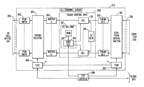
Depicted in FIG. 3 is transmit circui.t 213 of
time slot interchange unit 208. This well-known transmit
circuit described in the previously cited Bell ~y~em
Te~ , of September, 1977, includes 8X8
terminating serial switch 301, a plurality of timing
detectors such as 302, a plurality o:E buffer memories such
as 303, a recorrelator 304, and a plurality of PCM
35 transmitters such as 305 all under the control of time
slot counter 306, time slot memory 307, and time slot
interface controller 308 interconnected as shown.
-- 10 --
Interconnected between each o~ the timing detectors and
the buffer memories is fraud control unit 309 also under
the control of TSI controller 308. This fraud control
unit includes generator 310 for generating idle code for
each of the outgoing transmit paths served by the outgoing
transmit circuit and a plurality of selector circuits such
as 311 selectively operable for directing and inserting
either the idle code from the generator or the
communications on the transmit path from the caller into
buffer memory 307 for the final stage of time division
switching. Each selector is controlled by idle code
selector control unit 312 which is under the control of
central processor 202 via the TSI controller 308.
Selector controller 312 includes a well-known busy/idle
memory map in memory 313 for storing the busy/idle state
of each path served by transmit circuit 213 and well-known
control circuitry 31A for indicating the stored state of a
path to the associated selectors. For example, when an
idle state is indicated by controller 312, selector 311
directs and inserts the idle code from generator 310 into
buffer memory 303 indicative of an idle or
noncommunicative state o~ the path. When selector
controller 312 indicates a busy or communicative state,
selector 311 inserts the communications on path 256 from
the caller into buffer memory 303 for transmission on one
of the outgoing paths such as outgoing transmit path 255.
When a call for a four-wire call connection is
received by toll office 101, switching network 201 under
the control of central processor 202 establishes two
unidirectional call connection paths that are assigned or
allocated by the central processor to serve the call. To
prevent calls including fraudulent ones from propagating
through toll o~fice 101, central processor 202 sends an
order to fraud control unit 309 to disable communications
on the established transmit path from the calling to the
called line. As a result, the established transmit path
is maintained in a noncommunicative state. This is
accomplished by setting the state of the transmit path in
the busy/idle memory map of selector control 312 to idle.
When this idle state is indicated, selector 311 directs
and inserts idle code from generator 310 into buffer
memory 303 rather than communications on TMS path 256 from
the caller when in the busy state. Thus, any
communication from the calling to the called line is
prevented until a valid answer signal is received from the
called line. Since the established receive path is
maintained in a communicative state, call progress tones
such as ringing, busyr or recorded announcements will all
be heard by the callerO However, with the communirations
disabled on the established transmit path, it is
impossible for the caller to be heard by the person at the
called line or for a "blue box" user to forward signals
until a valid answer signal is returned for the call.
When a valid answer supervision is returned to
the toll office, as with most legitimate calls, the
central processor sets the busy~idle map for the call in
selector control 312 to the busy state. Selector 311
responds by inserting the communications on TMS path 256
from the caller into buffer memory 303 which is then
switched onto outgoing path 255 to the called line. When
answer supervision is not returned such as in the case of
a fraudulent call, idle code is continually inserted into
outgoing transmit path 255 from the calling to ~he called
line thereby maintaining the established transmit path in
a noncommunicative state.
Depicted in FIG~ ~ is a flow chart illustrating
the method of processing calls and, in particular,
preventing the completion of calls through a toll
switching system office until a valid answer supervisory
signal is received for the call. This method is
implemented by program instructions that are stored in the
central processor of a toll switching office and with the
previously-described fraud control unit in the transmit
portion of the switching and permuting circuit in the TSI
- 12 -
unit. For example, upon the receipt of a call from
calling customer line 153, the incoming call is routed
through switching network 201 to an outgoing trunk in a
well-known manner under the control of program
S instructions in central processor 202 (block 401). This
is accomplished by the central processor assigning or
allocating two unidirectional call connection paths to
serve the call ~block 402) and sending orders to the
switching network to establish the two assigned or
allocated unidirectional call connection paths through the
switching network to serve the call (block 403). The
established transmit path provides for the transmission of
communications from the calling to the called line,
whereas the established receive path provides for the
transmission of communications from the called line
towards the calling line.
The central processor then disables
communications on the transmit path from the calling to
the called line by sending a separate disable order to the
busy/idle memory map of selector controller 312 to
indicate an idle state to selector 311 for indicated
transmit path 255 (block ~04)~ The established receive
path is maintained in a communicative state to facilitate
the transmission of call progress signals to the calling
line tblock 405). Sensing the idle state, selector
control 312 directs selector 311 to direct and insert idle
code from generator 310 into buffer memory 303 for
transmission to the called line. The idle code inserted
on the transmit path is sent to the calling line and
maintains the path in a noncommunicative state
(block 405). The separate disable order does not
interfere ~7ith any of the normal call processing routines
executed by the processor and avoids the need for
executing two sets of orders to set up separate transmit
and receive paths at different times.
- 13 -
The toll o~fice normally waits for valid answer
supervision from the calling line for the call and
continues to maintain the transmit path in a
noncommunicative state until answer supervision is
received for the call. When valid answer supervision is
received from the calling line, the central processor
removes the disabling of communications on the transmit
path by simply sendin~ an order to set the busy/idle
memory map of selector control 31~ to a busy state for the
transmit path ~block 407). The selector for the
associated transmit path then inserts the communications
on transmit line 256 from the caller into buffer
memory 303 for transmission to the called line. The
withdrawa~ or removal of idle code from the transmit path
causes the transmit path to enter a communicative state
where caller communications pass freely from the calling
to the called line. When valid answer supervision i5 not
returned, the transmit path remains in a noncommunicative
state which will typically cause the caller to hang up.
As an alternative method of preventing
fraudulent calls through the network, the central
processor may be programmed in a well-known manner to
first establish a receive path from the called to the
calling line to allow normal call progress signals to be
heard by the caller. When answer supervision is returned
from the called line, the central processor sends a second
set oE orders to the switching network to set up a
separate transmit path from the calling to the called line
to complete the two way communication. This method
requires additional programming instructions and real time
on the part of the central processor r hut is an
alternative to the previously described method oE and
system for preventing calls from completing through a toll
switching system office until answer supervision is
received for the call.
It is to be understood that the above-described
system and method for preventing fraudulent calls from
completing through a switching network is merely an
illustrative embodiment of the principles of this
invention and that numerous other methods and apparatus
may be devised by those skilled in the art. In
particular, the communications on the transmit path may be
disabled at each switching system which is utilized to
complete a four-wire call connection between a called and
a calling line. Furthermore r one of the switching systems
such as the terminating toll office may be designated to
only disable communications on the transmit path at that
switch while the other switching systems complete a call
in a normal fashion. While the illustrative embodiment
discloses disabling communications on the transmit path or
maintaining the transmit path in a noncommunicative state
until answer supervision is received, the receive path may
be disabled instead of or in combination with the transmit
path of a four-wire call connection.