Note: Descriptions are shown in the official language in which they were submitted.
~3~
"AIR- AND DUST-PROOF COVER FOR
FLUSH MOUNTING ~IRING FIXl'URE"
SPECIFICATION
T~CHNICAL BACKGROUND OF THE INVENTION
. . _ . . . _ . _ _ _
This invention relates to a cover which prevents air
and dust from entering a flush mounting wiring fixture.
In general, where the flush mounting wiring fixture is
ins-talled in a recess made in a building wall or the like
structural member, there often exists an opening or
clearance left around the wiring fixture, and it is likely
that, in a season involving, for example, a large
temperature difference between the interior and ex-terior
of a room, ambient air of a relatively low -temperature
comes through such clearance into the wiriny fixture of a
rela-tively high atmospheric temperature so as to cause
water condensed as droplets on electrically conductive
parts within the wiring fixture, and such en-try of ambient
air is accompanied with dust which also en-tering -the
fixture. With a provision of an air- and dust-proof cover
which encloses -the Élush moun-ting wiring fixture,
thereEore, -the ambient air and dust can be prevented from
entering the fix-ture and the water condensation and dust
stain within the fixture can be eventually prevented from
occurring.
DISCLOSURE OF PRIOR ART
~s known air- and dust-proof covers of the kind
referred to, the ones disclosed in U.S. Patent No.
4,345,693 to G.R. Balkwill et al. and U.S. Patent No.
! . 2
~.
.
'; ." ~ ....
~L~73~9~
4,408,695 as a continuation-in-part of the former may be
enumera~ed. In these Balkwill et al. paten-ts, there are
suggestad alr and moisture resistant covers formed in a
bottomed box shape with a plastic material, which is
` 5 opened on top side to house therein a flush mounting
wiring fixture to be installed in a structural member. In
these instances, the air and moisture resistant cover is
secured to the structural member together with the wiring
fixture for preventing air and moisture as well as dust
from entering the fixture.
When the air and moisture resistant cover of Balkwill
et al. is used, interconnection of such electrical wires
as VUF cables, VVF cables or the like terminals of the
wiring fixture is to be realized by passing the wires
through punched holes in the cover and connecting it to
the terminals, in which event the material oE the cover
will cllngingly engage about insulation coating of the
wires at the punched holes to provide a tight fitting, for
preventing the air entry to some extent. However, this
cover has such a problem thatl once the cover involves any
cr~ac]cing at the punched holes or any thermal contraction
due to a change in the ambient temperature, there occurs a
small gap between the wires and the cover at the punched
holes and the a.ir entry prevention becomes insufficient.
Japanese Patent ~ppln. Laid-Open (KOKAI) Publication
No. 60-180~11 of S. Kimura et al. may also be enumera-ted
as a prior art but substantially oE the same technical
level as that referred to in the above.
-- 3 --
- .. ....... ,;: . .. .. .
' '
.:,
TEC~INICAL FIEI.D OF THE INVENTION
A primary object of the present invention is, therefore, to
provide an air- and dust-proof cover which can enclose the wiring
fixture flush-mounted in a structural member with a sufficient
airtightness, while maintaining the sufficient airtightness also
at portions of the cover for passing therethrough the connecting
wires to the terminals of the wiring fixture, and thus can
prevent any condensation of moisture at electrically conductive
parts within the wiring fixture and any entry of dust or foreign
0 matter into the wiring fixture.
According to the present invention, the above object is
attained by providing an air- and dust-proof cover for a flush
mounting wiring fixture, the cover comprising a housing part for
housing therein said wiring fixture and to be accommodated in a
recess made in a building structural m~mber with the wiring
fixture housed, a flange part extended around the housing part
to lie over peripheral edges of the recess of the structural
member and having a reinforcing plate embedded therein, and
cylindrical parts respectively extruded both inward and outward
from the housing part and having therein a f].exible thin-wall for
penetrating therethrough connecting wires.
According to the air-and dust-proof cover of the present
invention arranged as above, the connecting wires are to be
connected to terminals of the wiring fixture housed in the
housing part by guiding a connecting end of
., .
.
...,
73~
the respective wires in-to each of the cylindrical parts,
breaking -the thin-wall in the cylindrical part wi-th tip
end of the wire and passing the wire -through the
cylindrical part up to one of the terminals, whereby the
cover can be prevented substantially from crac~ing a-t the
wire passing portion and from being affected by a
contraction due to any ambient temperature change, and the
cover can be provided reliably with a high airtightness.
Other objects and advantages of the present invention
shall be made clear from the following description of the
invention detailed with reference to preferred embodiments
shown in accompanying drawings.
BRIEF EXPLANATION OF THE DRAWINGS
.... . . . __
FIGURE 1 is a plan view in an embodimen-t of an air-
and dust-proof cover according to the present inven-tion;
FIG. 2 is a side view of the cover of FIG. 1, with a
part of the cover shown in section;
FIG. 3 is an endwise view of the cover of FIG. 1, with
a part shown in section;
FIG. 4 is a ragmentar~ perspective view as magnified
of the cover of FIG. ]., shown w.ith a mourlting means
including a clamp for installation of the cover in a
structural member;
FIG. 5 is a cross-sectional view of -the cover of FIG.
1 showing a state in which the cover is installed in a
recess in the structural member, with a flush mounting
wiring fixture housed in and secured to the cover;
FIG. 6 is a plan view in another embodimen-t of the
-- 5 --
3~
air- and dus-t-proof cover according to the presen`t
inventlon;
FIG. 7 is a side view of the cover of FIG. 6, with a
part of the cover shown in section;
FIG. 8 is an endwise view of the cover of FIG. 6, with
a part shown in section;
FIG. 9 is a cross-sectional view of the cover of FIG.
6, shown in a state in which the cover is installed in a
recess in a structural member wi-th a wiring fixture housed
in and secured to the cover; and
FI~7. 10 is a perspective view of still ano-ther
embodiment of the air- and dust-proof cover according to
the present invention, with a separator shown as
disassembled.
While the present inven-tion shall now be described
with reference to the preferred embodiments shown in the
drawings, it should be understood that the in-ten-tion is
not to limit the invention only to -the particular
embodiments shown but rather to cover all alterations,
modifications and equivalent arrangements possible wi-thin
the scope of appended claims.
DISCL,OSURE OF PREF'ERRED EMBODIMENTS
_ __ .... ~., .... .. _ __.
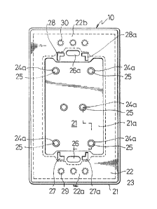
Referring to FIGS. 1 to 5, there is shown an air- and
dust-proof cover 10 in an embodiment according to the
p:resent invention, which is fitted into a recess 12 made
in a structural member 11 to accommoda-te therein a flush
mounting wiring fixture 13.' More specifically, the cover
10 is made of such a flexible material as a -thermoplastic
~, :
~2'73~
resin, rubber or the like, to have a box-shaped housing
part 21 for enclosing therein the flush mounting wiring
fix-ture 13 or, in other words, to have the fix-ture housed
therein. The housing part 21 is formed to have at its
opening edge an integral flange part 22 which extends
along i-ts entire periphery to be able -to lie over
peripheral edges lla of the recess 12 of the structural
member 11. Further, a reinforcing member 23 of a metallic
material, preferably an iron pla-te or the like is embedded
by insert molding in the flange part 22 alony the entire
periphery of the housing part 21 to prevent it from being
readily deformed. In this connecti.on, the housing part 21
may be made initially separately from the flange part 22
and then be integrally bonded thereto by an adhesive or
the like.
The housing part 21 is provided in its bottom wall 21a
with a plurality of cylindrical parts 24 which extrude
inward and outward at right ang].es w.ith respect to the
bottom wall 21a, at positions corresponding to
dispositions of terminals O:e the wiring fixture 13 to be
housed in the housing part 21. A portion 2gb of each
cylindrical part 2g extruded out Oe the bot-tom wall 21a is
made to be shorter than the o-ther inward extruded portion
24a of the same cyli.ndrical par-t while the both portions
2ga and 2gb are coaxial, and these cylindrical parts 2g
are formed respectively to have a thin-wall portion 25
which closes intermediately axial hole of the cylindrical
parts preferably with a thickness smaller than other
~L~'7~
por-tions of the housing part 21, so tha-t the thin-wal:L
portion 25 will be sufflciently flexible for being readily
broken by a leading end l~a oE connec-ting wires 14
provided inside -the struc-tural member 11 to pass -them
through the housing part~
In addition, the flange par-t 22 i.s provided in both
opposing edge parts 22a and 22b with thin-wall por-tions 26
and 26a which are located at positions opposed to each
other longitudinally through open end oE the housing part
21, for penetrating therethrough fastening screws 15 and
lSa, and on both sides of the respective thin-wall
portions 26 and 26a of the flange part 22 with two pairs
of L-shaped thin-wall portions 27, 27a and 28, 23a for
penetrating therethrough respective hook portions 17 and
17a of a clamp 16 for securing the Elange part 22 to the
peripheral edges of the recess 12 of the s-tructural member
11. I'wo sets of -thin-wall portions 29 and 30 may be
fur-ther provided in the vicinity of the thin-wall portions
26 and 26a oE the flange part 22 .Eor allowing set screws
(not shown) to be passed therethrough when a decorative
cover plate 18 of the :Eixture is to be secured to the
1ange part 22 as re~uired.
Now, explanation wi:Ll be made as to the manner in
which the air- and dust-proof cover 10 according to the
present invention is mounted to the structural member 11
as housed in its recess 12 together wi-th the wiring
fixture 13. First, the connecting ends 14a oE the wires
1~ of power supply wiring inside -the member 11 are
-- 8
inserted respectively into each of the extruded portlons
24~ of the cylindrlcal parts 24 outslde the bo-t-tom wall
21a, urged against the thin-wall portion 25 -to break it,
and led -through the inward protruded portion 24a of the
respec-tive cylindrical parts 24 in-to the interior of the
housing part 21. In this case, the flexible thin-wall
portion 25 broken by the connecting ends 14a of the wires
14 engages the periphery of the wires resiliently so as to
prevent air from passing through the broken thin-wall
portion 25. When -the Eull length of the cylindrical parts
24 is made long enough, the interior of these cylindrical
parts 24 can be maintained subs-tantially in a solid sta-te
with the wires disposed therein, the air-entry prevention
can be achieved in -this respect, too, and -the cylindrical
parts 24 can maintain the high non-ventila-tion property.
In addition, the outward protruded portions 24b of the
cylindrical par-ts 24 made relatively shor-ter are efEective
to prevent such disadvantages Erom occurring that the
leading ends 14a oE the wires urged into the outward
protruded portions 24b to break the thin-wall portions 25
therein may cause therm resiliently bowed -to entail in a
simultaneous bowing oE the inward extruded portions 24a
and to leave them as bowed even aEter the mounting, and
that the leadlng ends 14a may hit the inner periphery oE
the portions 24b to render the wire passing to become
troublesome. Accordingly, the wires 14 can be airtightly
passed througll the hous3tlg part 21 as guided substarltially
at right angles with respect to the bo-ttom wall 21a.
v~
3~
Nex-t, the hook portlons 17 and 17a of the clamps 16
and 16a are urged to penetrate through laterally ex-tending
lec~ par-ts of the L-shaped thin-wall por-tions 27, 27a and
2~3, 28a of the flange part 22, and are then shifted into
vert.ically extendlng par-ts of these thin-wall por-tion to
be hooked on the upper surface of -the flange part 22.
Here, threaded holes made in the clamps 16 and 16a are
posltioned to align with the other thin-wall portions 26
and 26a of the flange part 22, and the clamps 16 and 16a
are hung at their outward extended end onto inner side
face of the peripheral edges of -the recess 12 of the
struc-tural member 11. Then, a main body of such wiring
fix-ture 13 as a small switch, electrical ou-tlet or the
like is housed in -the housing part 21 so that peripherally
extended flange of a top plate of the fixture body will be
seated on the flange part 22 of the cover 10. The set
screws 15 and 15a are driven through the flange of the
fixture 13 and the thin-wall portions 26 and 26a of -the
flange part 22 of the cover 10 into the threaded holes of
the clarnps 16 and 16a -to fasten the fi~ture 13 against the
cover 10, while the flange part 22 of the cover 10 and the
flange of the wiri.ng fixture 13 are tightly secured by the
clamps 16 and 16a and set screws lS and l5a to the
per:ipheral edges or the recess 12 of the structural member
11, and therefore ttle wiring fixture 13 and the cover 10
are fixedly mounted to this structural member. In this
case, the airtightness can be achieved at the thin-wall
portions 26, 26a, 27, 27a, and 2~, 2~a, througll which the
-- 10 -- ,
3~
screws 15, 15a and hook portions 17, 17a of the clamps 16
and 16a are passed substantially in -the same manner as in
the case of the oregoing thin-wall portions 25, because
these thin-wall por-tions broken are to resilien-tly
intimately engage the screws and the hook portions.
Moreover, since -the flange part 22 of the cover 10 is
depressed by the fastening force of -the set screws 15 and
15a, the airtiyhtness can be further enhanced between the
peripheral edges lla of the structural member 11 and the
top pla-te of the wiring fixture 13. That ls, as a whole,
the wirlng flxture 13 can be housed a-t lts perlpheral slde
faces and bottom face in a space having a high
airtightness, while the top wall of the wiring flxture 13:
can be retalned also ln the airtlght s-tate wi-th lts own
alrtlgh-t s-tructure as has been well known.
Although the reinforclng plate 23 has been lllus-trated
by dotted lines as not éxpanded to a zone of -the flange
part 22 including the thln-wall por-tlons 26, 26a, 27, 27a,
28 and 28a in the Eoregoing arrangement, the reinforclng
plate 23 may be expanded to this zone and holes may be
made at positions corresponding to the respective
thin-wall port:ions in -the expanded reinforcing plate 23,
if required. While the th:ickrless of the respective
thin-wa:Ll portlons sholl].d depend on the s-trength of -the
connectlng en~s 14a o~ the cable 14 and so on, it is made
-to be, for example, about 1 mm. the perlpheral edges of
the flange part 22 are for~ned preferably to be sloped
outwardly as illustrated for the purpose of avoiding any
-- 1 1 --
. ~
~3~
deposition -thereon of dust. E'urther, it is possible to
mount the decorative cover pla-te 18 onto the wiring
fixture 13 except for an operating surface oE the fixture
13, in which event, too, the airtigh-tness may be
maintained in such that screws passed through a middl.e
frame (not shown) for mounting the cover plate 18 or
directly through the cover plate 18 are driven to further
penetrate through other thin-film portions 29 and 30
p.rovided in the flange part 22, so as to secure the cover
plate to the case 10 or fix-ture 13 in any known manner.
In addition, the airtightness at the respective thi.n-wall
portions through which the screws and the like members
~enetrate may be improved by applying an adhesive or the
like to these portions after fixa-tion of the members.
Refexring now to FIGS. 6 to 9 showing an air- and
dust-proof cover 40 in another embodimen-t of the present
invention, substantially the same cons-tituent members as
those in FIGS. 1 to 5 are denoted by the same reEerence
numerals but added by 30. While the embodiment oE FIGS. 1
to 5 is of the cover which is suitable for use in mounting
such wiring Eixture as the small switch of which operating
surface is to be projectecl, -the air- and dust-proof cover
40 of the present embodiment is suitable Eor use with such
a wiring fixture as an electrical outlet 43 having an
operating sur~ace not projected and can be covered with a
cover plate 49 through a decorative frame 48 when the
outlet is not used. In this case, a flange part 52 of the
cover 40 is provided at its ~our corners with L-shaped
- 12 -
~..
..
. : ,
~3~
projections 61, 61a, 62 and 62a which serve -to position
corresponding corners of the decorative frarme 48, so tha-t
the decorative frame 48 seated on the flange part 52
through these projections can be mounted on the :Elange
part 52 by means oE screws 46 (only one of which is
illustrated in FIG. 7) passed -through thin-wall portions
59 and 60 provided in the flange part 52. In an event
where an embedding box 50 is ernployed as embedded in a
struc-tural member 41 and a housing part 51 of the cover 40
with -the wiring fixture 43 housed therein is to be fi-t-ted
into -the embedding box 50, set screws 45 and 45a passed
through thin-wall portions 56 and 56a also in -the flange
part 52 are fastened into corresponding threaded holes in
the embedding box 50, and the cover 40 and wiring fixture
43 can be secured to the embedding box 50. I-t will be
appreciated that other arrangement and operation of the
presen-t embodiment are substantially the same as those of
the foregoing embodiment, and that the wiring fixture 43
is disposed in a highly airtigh-t space of the cover 40.
In FIG. 10, there is shown an air- and dus-t-proof
cover 70 in still another ernbodiment of the present
invention, in which substantially the same constituent
members as those of the embodiment shown in E'IGS. 1 to 5
are denoted by the same reference numerals but added by
60. In the present embodiment, the air- and dust-proof
cover 70 is of a type i.n which two of the covers of, for
example, FIGS. 1 to 5 are jointly arranged, and is
provided in middle position of opposing longer, inner side
- 13 -
~2~301~
walls and of inner bottom wall with a groove 93 which can
fittingly receive a separator 94. It will be understood that
this separator can electrically insulat.ingly separate a housing
chamber 81 of the cover 70 into two rooms so that, for example,
connecting ends of a low-voltage wire can be connected in one of
the rooms while connecting ends of a low-current wire can be
connected in the other room and thus different types of the
wiring fixtures can be fitted into the single cover 70. Other
arrangement and operation of this embodiment are substantially
the same as those of the foregoing embodiments, and the different
type wiring fixtures can be housed in the cover 70 as electrical-
ly isolated from each other and as disposed in a highly airtight
space of the cover 70.
- 14 -
. ...