Note: Descriptions are shown in the official language in which they were submitted.
~73135
APPARATUS FOR DETECTING POSITION OF FAULTY LIGHT
EMITTING ELEMENT IN LARGE SCREEN DISPLAY SYSTEM
BACKGROUND OF T~E INVENTION
Field of the Invention
The present invention relates to an apparatus
for detecting the position of any faulty light emitting
element upon occurrence of failure in one Gr more of
multiple display elements arrayed on the screen of a
large-sized display system.
Description of the Prior Art
In the recent sports stadiums or the like such
as baseball stadiums, succor stadiums and so forth where
multiple spectators gather, there is practically used a
large Screen display system - e.g. known by the trade
name of Aurora Vision or Diamond Vision - which is
equipped with a multiplicity of light emitting sources
arrayed in columns and rows to constitute a large-sized
screen and displays still images, motion images, charac-
ters and so forth on such screen for giving specific
information to the spectators.
The above large screen display system principally
comprises a display means including a large-sized screen,
a power supply panel and a display controller; and an
- 1 -
~273135
operating means including a computer, a character e~iting
terminal, a screen control terminal and a special effect
switcher. The large-sized screen is composed of a
multiplicity of light emitting elements such as incandescent
lamps or light source tubes of recently developed high-
luminance CRTs which are arrayed in columns and rows
vettically and horizontally to constitute a combination of
many units in accordance with the screen size, wherein each
unit is composed of a predetermined number of such elements
as, for example, 4 x 8 = 32.
When there occur faults of multiple light emitting
elements in the display means constituting the large screen,
the information such as images or characters displayed on
the screen fail to be transmitted properly to the
spectators, so that fast replacement or repair of the faulty
elements is necessary. And to perform such repair, it is
requisite to first detect which of the multiple light
emitting elements are faulty.
To enahle the prior art to be explained with the
aid of diagrams, the figures of the drawings will first be
listed.
Fig. 1 is a front view of a conventional apparatus
for 3etecting the position of a faulty light emitting
element in a large display system;
Fig. 2 is a right side view of the apparatus shown
in Fig. l;
Fig. 3 is a block diagram of an apparatus of the
present invention for detecting the position of a faulty
i;273~3S
light emitting element in a large screen display system;
Fig. 4 is a flow chart schematically showing the
steps of a blank display test conducted in an exemplary
position detecting apparatus of the invention;
Fig. 5 (a), (b) and tc) are front views
respectively showing a CRT screen, a large display screen
and enlarged light emitting elements of one display unit in
the test of Fi~. 4;
Fig. 6 schematically illustrates how data are
transferred between the component devices in the test of
Fig. 4;
Fig. 7 is a flow chart schematically showing the
steps of a cross pattern display test conducted in another
exemplary position detecting apparatus embodying the
invention;
Figs. 8 (a), (b) and (c) are front views
respectively showing a CRT screen, a large display screen,
and enlarged portions of light emitting elements crossed in
a column and a row; and
Fig. 9 schematically illustrates how data are
transferred in the test of Fig. 7.
In the prior art, there is known one exemplary
apparatus of Figs. 1 and 2 for positional detection of
faulty light emitting elements, wherein a large screen 2 of
a large-sized display system 1 is composed of a
multiplicity of display units 3 ... and is connected to an
- unshown display controller. Each of the display units
- 3 -
~:27:~S
3 consists of, for example, an array of 32 light emitting
elements 4 (eight in a row and four in a column) such as
incandescent lamps or high-luminance CRTs (cathode-ray
tubes), and the elements 4 are assorted in three primary
colors as red (R), blue (s) and green (G). In an arbitrary
display unit 3n out of the entire units 3 in Fig. l, the
light emitting elements 4 are arrayed as illustrated.
For detection of any fault such as breaking or
luminance reduction in the individual light emitting
elements 4 ... of the display unit 3n, a faulty-element
position detecting apparatus lO is employed. The detecting
apparatus lO principally comprises a power supply 11 fed
with external detecting power via a power cable 12, and a
detector 21 disposed above the power supply ll and serving
to detect the position of each faulty light emitting
element. An operating panel 13 is disposed on the front
of the power supply ll and is equipped with a voltmeter
14, an ammeter 15, a selector switch 16 for selecting a
desired lighting display mode such as lighting of all
elements of a unit or lighting of half elements of a unit
or lighting of each element of a unit and a lighting switch
17 for simultaneously turning on the entire light emitting
elements in the display unit 3. Three cables extending fro~ the
detector 21 have, at the fore ends thereof, plugs connectable
to connectors (not shown) of the display unit 3. The cables
-- 4
~Z731~S
consist of an output data cable 22, a set/reset signal
cable 23 and aDC power/AC power cable 24 for respectively
supplying an output data signal, a set/reset signal and
a DC power/AC power from the detector 21 to the display
unit 3. Light acceptant parts 25 ... for insertion of
luminous parts pointed ends of the light emitting elements
4 ... on the back of the display unit 3 are arrayed on
the front of the detector 21 correspondingly to the light
emitting elements 4 ..., and unit testing positioners 18
and 19 are disposed in front of the light acceptant parts
25 above the pwer supply 11. A luminance adjusting dial
assembly 26 is disposed above the light acceptant parts
25 ... of the detector 21 so that, for example, the
luminance of red ligh emitting elements R can be adjusted
by a dial 26a, the luminance of blue light emitting
elements B by a dial 26b, and the luminance of green light
emitting elements G by a dial 26c, respectively. On the
panel where 'he luminance adjusting dial assembly 26 is
located, pairs of light emitting diodes (LEDS) 27 and
28 are provided for the individual light emitting elements
of the display unit 3. For example, each pair of such
LEDs consists of a diode 27 turned on at the luminance of
a predetermined low level and a diode 28 turned on at the
luminance of a predetermined high level.
In the faulty-element position detecting apparatus
10 having the above-described structure, the following
æ7~L~S
operation is performed.
First, as shown in Fig~ 1, an arbitrary display
uni~ 3n in the large screen 2 of the large display system
1 i5 removed from the screen 2. Then the display unit 3n
is slid as shown in Fig. 2 along the unit testing posi-
tioners 18 and 19 located above the power supply 11 of
the position detecting apparatus 10, and luminous parts
as pointed ends of the light emitting elements 4 are
inserted in~o the light acceptant parts 25 ... of the
detector 21 in the position detecting apparatus 10. And
simultaneously the lighting test cables 22 - 24 are
connected to unshown connectors of the display unit 3n.
In a test for detecting any fault such as
breaking of the light emitting elements 4 ..., the lighting
switch 17 is turned on to supply power to the display
unit 3n through the cables 22 - 24, and the operator
visually checks whether the entire li~ht emitting elements
4 ... (e.g. 32 elements in the example illustrated) arrayed
in the display unit 3n are turned on. In case one of the
light emitting elements 4 ... fails to be turned on, the
faulty element 4n is replaced.
Subsequently, when detecting whether luminance
reduction is present or not in any of the light emitting
elements 4 ..., scale "ALL" is selected by the selector
switch 16 after placing the display unit 3n at a pres-
cribed position. Since the entire light emitting elements
-- 6 --
~731:~S
~ ... of the display unit 3n are turned on, it is possible
by adjustment of the individual dials 26 to check whether
a predetermined luminance as a whole is retained or not
from turn-on of the LEDs 27 and 28.
Relative to the conventional faulty-element
position detecting apparatus of the aforementioned struc-
ture that performs the above operation, an exemplary
circuit configuratior. is disclosed in Patent Publication
No. S5 (198G) - 749 issued from the Japanese Patent
Office. However, "Electric Display Board Monitoring
Apparatus" according to the above invention is not equipped
with a circuit to conduct a luminance reduction test. In
the aforementioned procedure, the operator detects a faul-
ty lightemitting element 4n visually with his naked eyes
by sequentially turning on the light emitting elements
4. Meanwhile the apparatus disclosed in the above patent
publication is e~uipped with "a circuit for scanning and
detecting the presence or absence of a breaking signal",
so that it is capable of automatically counting the number
of faulty light emitting elements by means of a counter
and displaying the positions thereof in a continuous
lighting test mode selected by setting at scale "SEQ".
However, there still exist the following problems
in such conventional detecting apparatus.
Firstly, in conducting the above test by se~uen-
tially removing the entire display units 3 ... incorpo-
-- 7
~313S '
rated in the large screen 2 of the large display system
1 and setting each display unit in the detecting apparatus
10, an excessive burden is imposed on the operator and,
with dimensional increase of the large display system 1,
positional detection of faulty light emitting elements is
operationally complicated to consequently bring about a
failure in achieving complete and precise maintenance of
the large display system 1.
Secondly, in case no scanning detection circuit
is provided, the detection is dependent mostly on the
visual inspection by the operator, and therefore exact
positional detection of a faulty light emitting element
is not attainable. And even with the provision of a
scanning detectiGn circuit, visual inspection is still
requisite in the process of finding, out of the large
screen 2, the display unit 3n where the faulty light
emitting element is existent, hence rendering accurate
detection of the faulty portion impossible.
Thirdly, in the conventional position detecting
apparatus where the scale "ALL", "HALF" or "SEQ" is
selected by the test-mode setting switch 16 to conduct a
test in each selected mode as well as a lighting test and
a luminance reduction test, it is impossible to individually
detect a breaking fault or luminance reduction with respect
-- 8 --
1~73~13S
to any specific light emitting element 4, and regardless
of such inevitable removal of each display unit 3 from
the large screen 2 for testing, the detecting operation
is rather rough and exact control is not achievable for
the system, hence lacking in reliability for detection of
any faulty light emitting element.
And fourthly, for enabling continuous use of the
large display system 1, it is necessary to install a
large-sized position detecting apparatus 10 which is
dimensionally a multiple of the display unit 3 and, as
the number or size of display units 3 ... becomes
greater with further dimensional extension of the display
system 1, there arise some problems to be taken into
consideration, such as increased economical burden on
purchasers, need of a sufficient space for installation
of the position detecting apparatus and so forth.
SUMMARY OF THE INVENTION
In the apparatus of the present invention for
detecting the position of a faulty light emitting element
in a large screen display system, it is a first object to
enable an operator to perform the positional detection of
any faulty light emitting element without the necessity
of removing any display unit from a large screen, thereby
~273135
alleviating the working burden on the operator.
A second object of the invention resides in
mechanizing, by a combination of a CRT display and a
keyboard, the detection of a faulty display unit in the
large screen and also the detection of a faulty light
emitting element in the display unit that have been
executed heretofore merely by visual inspection of the
operator, thereby achieving accurate positional detection
of any faulty light emitting element.
A third object of the invention is to realize
facilitated detection of the exact position of any faulty
light emitting element in a specific display unit by the
above combination of a CRT display and a keyboard, hence
enhancing the reliability in the detecting operation.
And finally a fourth object of the invention is
to reduce the overall production cost as well as to
minimize the required space for installation by incorpo-
rating a faulty-element position detecting apparatus in
the large screen display system.
For attaining the objects mentioned, in the
apparatus of this invention designed for detecting the
position of a faulty light emitting element in a large
screen display system which is equipped with at least a
character processor and a motion image processor as
-- 10 --
~73i~.~;
display control means, there are included a CRT display
device for displaying the positions of light emitting
elements being driven out of a multiplicity of elements
arrayed in colu~ns and rows, and an input device connected
to both the CRT display device and the character processor
and serving to turn on or off a group of light emitting
elements in a desired area by inputting a drive command
signal to the motion image processor via the character
processor.
DETAILED DESCRIPTION OF THE PREFERRED EMBODIMENTS
Hereinafter an exemplary embodiment of the present
invention will be described with reference to the
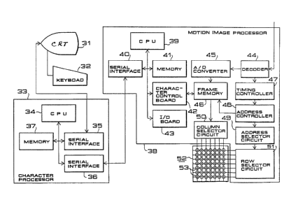
accompanying drawings. In Fig. 3, there are shown a CRT
display 31 having a character display function; a keyboard
32; a c'naracter processor 33 for executing video display,
digital display or special effect display; a CPU
~,,
~3~
board 34; a serial interface 35 for transferring data to
and from the CRT display 31; a serial interface 36 for
transferring data to and from an undermentioned motion
image processor 38; a memory board 37; the motion image
processor 38 for executing video display by processing
video signal, or executing digital display or sPecial
effect display in response to diyital signal received from
the character processor 33; a CPU board 39; a serial
interface 40 for transferring data to and from the charac-
ter processor 33; a memory board 41; a character controlboard 42 for processing the character display; an input/
output board 43; a decoder 44 for decomposing the received
video signal into three color components of red, green and
blue and generating a synchronizing signal; an A/D
converter 45 for converting three video (analog) signals
of red, green and blue into digital signals; a frame
memory 46 including a video memory, video mask memory or
character memory in conformity with each purpose and
serving to store the video data converted into a digital
form or the character data or mask data transferred from
the character control board 42; a timing controller 47
for generating video data write addresses and A/D con-
version sampling pulses; an address controller 48 for
generating video data read addresses and character data
- 12
~73~i
write/read addresses; an address selector circuit 49
for generating addresses and set/reset pulses used to
set or reset the signal for turning on or off undermen-
tioned light emitting elements 53, a column selector
circuit 50 for selectively latching 16 dots of the data
read out from the frame memory 46 and transferring the
latched data to the display board 2; a row selector
circuit 51 receiving the set/reset pulses and the addresses
and sending 8 bits of the set/reset signal at a time to
the display board; a display board 52; and light emitting
elements 53.
In the above embodiment, the following operation
is performed as shown in the flow chart of Fig. 4. To
begin with, an explanation will be given on the term
"blank display test" (hereinafter abbreviated to BDT).
According to this test, the light emitting elements 53
of an arbitrary display unit 54 are turned off in a state
where a video is presented on the display board 52 as
illustrated in Fig. 5 (b), and the position of the faulty
light emitting element 53n is detected by adjusting the
display unit to be positionally coincident with the element
53n. First, a video display (VD) key is depressed [ST-l].
Then the CPU board 34 receives VD data and sends a video
display command to the motion image processor 38 [ST-2].
~73~ 3~5
In response to this command, the video data is written
and read so that the video is presented on the display
board [ST-3].
Subsequently, a blank display test (BDT) key is
depressed ~ST-4]. Then the CPU board 34 receives blank
display data and reads out from the memory board 37 the
data for presenting a display test pattern of Fig. 5 (a)
on the CRT display 31, thereby displaying the image of
a blank pattern on the CRT screen as shown in Fig. 5 (a)
[ST-5]. In this stage, if a faulty light emitting element
53n is existent in the display unit 54, half the heaters
of one unit 54 are not energized as shown in Fig. 5 (b)
due to the fault of one light emitting element 53n, so
that the element 53 ... constituting half the unit are
turned off. Therefore, noting the dark portion of the
large display screen 52, a display unit 54 in the vicinity
thereof is designated with the X and Y positions [ST-6~.
Such designation is transmitted via the CPU 34 of the
character processor 33 to the CPU 39 of the motion image
processor 38 and, in response to the blank display test
(BDT) command, the CPU 39 writes and reads the address of
the light emitting elements 53 of the above display unit
54 in and from the frame memory 46, thereby turning off
the entire liyht emitting elements 53 of the desi.gnated
_ 14
~Z73~5
display unit 54 simultaneously [ST-7]. Fig. 6 shows how
the data are transferred between the character control
board 42 and the frame memory 46 in this step.
The data of the CPU board 39 representing one
address is composed of 8 bits, while the data of the
character control board 42 is composed of 16 bits.
Therefore the latter data ("l" or ~o~) is divided, when
written in the memory, into two at the least significant
bit of the address signal from the CPU board 39. Upon
completion of such writing, the CPU board 39 transfers
the data from the character control board 42 to the video
mask memory included in the frame memory 46 [ST-7]. In
the frame memory, the address of the video mask memory
and the address of the video memory are corresponding to
each other at l:l, so that the data written in the video
mask memory decides whether the data of the video memory
corresponding to the address is valid or invalid. For
example, the video data is rendered invalid when the
data is "l". In other words, the light emitting element
53 is turned off.
Upon termination of transferring the data to
the video mask memory, the mask data is read out and
merely the video data corresponding to the address repre-
sented by the mask data "0" is fed to the display board,
~313~;
tnereby turning off only the light emitting elements 53
of the display unit designated with, e.g. X -- 1, Y = 1.
In case the display unit turned off is not
coincident with the faulty light emitting element 53n, an
operation is so performed as to attain positional coin-
cidence therebetween by depressing the keys ~ , ~, ~ and -
~on the keyboard [ST-8] When the CPU board 39 receives
each key code, the X or Y value stored in the memory
board 41 is renewed. For example, 1 is added to the X
value in response to a key code -~ . And the result is
transmitted ~o both the CRT display 31 and the motion
image processor 38. Then the renewed X and Y values are
presented on the CRT display 31 [ST-9], while writing and
reading the data into and from the memory are executed
in the motion image processor 38 in accordance with the
X and Y values, so that the light emitting elements 53
of the display unit represented by the X and Y values are
turned off [ST-10].
The blank pattern display test is conducted in
the procedure mentioned above, and thus positional detec-
tion can be performed in a state where the display unit
including the faulty liaht emitting element 53n is k~pt
attached to the large display screen.
Now another embodiment of the invention will be
_ 16 _
~73~3~a
described with reference to Fig. 7 and the following.
Explaining first the term "cross display test" (CDT),
it is carried out by simultaneously turning on light
emitting elements 53 arrayed in a column X and a row Y
as shown in Fig. 8 (b) and (c), and then adjusting the
intersection of the column and the row to be positionally
coincident with the faulty light emitting element 53n,
thereby detecting the position thereof.
The steps of such cross display test are shown
in the flow chart of Fig. 7. In conducting the cross
display test, first the screen of the display board 52
is cleared, and then a cross display test (CDT) key is
depressed [ST-l]. In response to the CDT data, the CPU
board 34 reads out from the memory board 37 the data for
presenting the display test pattern (DTP) of Fig. 8 (a)
on the CRT display 31 [ST-2]. In Fig. 8 (a), ~ represents
the position of the light emitting element, and ~ repre-
sents the position of the display unit including such
light emitting element. First, the values of X = 1 and
Y = 1 are transmitted to the CRT display 31 [ST-3], where
X represents a horizontal address on the display board 52
and Y represents a vertical address thereon. Since the
CPU board 34 is transmitting the data of CDT mode to the
motion image processor 38, when the X and Y values are
~3~5;
designated by the keyboard 32 [ST-4], the CPU board 39
writes the data in the memory board 41 of the character
control board 42 in accordance with such X and Y values
[ST-5]. In Fig. 9, there is shown a procedure of writing
the data in the case of X = 1 and Y = 1. Fig. 9 i5 a
model diagram illustrating how the test data from the
CPU board 34 of the character processor 3 is written in
the character control board 42 of the motion image
processor 38. First, the CPU board 34 sends the test
data read out from the memory board 37 via the serial
interface 35 to the CRT display 31 and, after confirming
it, calls via 8-bit address buses Do, Dl .... D7 the test
data written in the memory board 37, i.e. the data corre-
sponding to the character control board 42. And posterior
to conversion of the test data into serial data by the
motion image processor 36, the CPU board 34 transmits the
serial data as cross display test data via the serial
interface 40 to the character control board 42 [ST-6]. As
mentioned previously, the data of the CPU board 39 repre-
senting one address is composed of 8 bits, while the dataof the character control board 42 is composed of 16 bits.
Therefore the latter data ("1" or "0") is divided, when
written in the memory, into two at the least significant
bit of the address of the CPU board 39. Upon completion
~ 18
~7~
of such writing, the CPU board 39 transfers the data from
the character control board 43 to the character memory
included in the frame memory 46 and, after termination of
the transfer, reads out the data [ST-7] and transfers it
to the large display screen 52 for visual presentation
thereon [ST-8]. This step is shown in Fig. 8 (b), where
the light emitting elements of one column and one row are
so turned on as to mutually intersect at the respective
X and Y values.
Subsequently, the light emitting elements of one
column and one row thus turned on are shifted vertically
and horizontally by manipulating the keyboard 32 while
watching the large display screen and the CRT test screen
(Fig. 8 (a)) [ST-9]. The values designated by the key-
board 32 are processed by both the CPU board 34 of the
character processor 33 and the CPU board 39 of the motion
image processor 38, and the addresses of the individual
light emitting elements 53 in the designated column and
row are written in and read out from the frame memory
46, whereby the entirety of such elements are turned on
simultaneously [ST-10]. Whether the faulty light emitting
element 53n is positioned at the column-and-row inter-
section is read out from a combination of the large display
screen 52 and the X and Y values on the CRT screen 31
-- 19
~73~3~-
[ST-11]. And when the position of such faulty element
is coincident with the intersection, the X and Y values
at the time are checked to termjnate the positio~al
detection. In case no coincidence is attained, the X
and Y values are redesignated [ST-12] and the on-state
light emitting elements are shifted vertically and
horizontally [ST-13], whereby the position of every
faulty light emitting element 53n can be detected.
For example, if there exist two faulty light
emitting elements 53n as shown in Fig. 8 (c), one faulty
element 53nl at the intersection of column X = ~ and
row Y = ~ is first detected, and then another faulty
element 53n2 at the intersection of column X =~ + 3 and
row Y = ~ is detected with rightward shift of three
columns.
Thus, as described hereinabove, the following
effects are achievable in the apparatus of this invention
designed for detecting the positions of faulty light
emitting elements in a large screen display system.
Firstly, the position of any faulty light emit-
ting element can be detected by contrasting the CRT with
the large screen and turning on or off an arbitrary group
of light emitting elements without removal of any display
units thereof that constitute the large screen, hence
_ 20
~273135
simplifying the work for positional detec-tion and realizing
complete and exact maintenance of the large screen display
system.
Secondly, any fault position can be accurately
located by the use of accessory devices to automatically
store or prin-t the coordinate values of the on-state or
off-state light emitting elements displayed on the CRT
screen. Consequently, even after turning off the entirety
cf the large display screen, it is still possible to
repair or replace any faulty light emitting element with
a normal one without failure.
Thirdly, remarkable effect can be accomplished
particularly in the cross pattern display test for posi-
tional detection, wherein light emitting elements of one
column and one row are turned on out of those arrayed in
multiple columns and rows, and the faulty light emitting
element is positionally so adjusted as to coincide with
the intersection of the column and the row, thereby
attaining desired positional detection with precision to
eventually enhance the reliability in the operation.
And fourthly, in the large screen display system
equipped with a display means and a control means, mere
additional connection of a CRT and a keyboard to the
operating part of the control means eliminates the
1;~73i:~;
necessity of providing a separate large detecting appara-
tus, hence reducing the production cost and minimizing
the space required for installation.
- 22 -