Note: Descriptions are shown in the official language in which they were submitted.
~ .
~L ~ 3~L~
The invention is related to electrically actuated lock mechanisms
and, in particular, to an electrically actuated lock n~chanisln for the rear
deck lid of an automotive vehicle.
Lock mecllanisms for the rear deck lid of automotive vehicles are
well known in the art. In general, most of the rear deck lid lockiny mecha- -
nisms are purely mechanical and incorporate a latch n~mber entrapping a
mating member, such as a lock bar. The locking mechanism may be attached to
the rear deck lid and the mating lock bar attached to a structural element
of the vehicle below the lower extremity of the rear deck lid opening, or
the locking n~chanisnl may be attached to a structural member of the vehicle
and the lock bar attached to the rear deck lid. Normally, the mechanical
locking mechanisnls are locked by slamming the rear deck lid closed causing
the lock bar to engage the latch member displacing it to a locked position
in which the lock bar is entrapped by the latch member. The latch member
is mechanically released from its locked position by the rotary motion of a
key actuated lock.
In recent years, rear deck lld lock mechanisms have been deve-
loped which permit the lock mechanism to be electrically unlatched from
- inside the vehicle's passenger compartment, as well as externally unlatched
by means of the key lock. Typical electrically released rear deck lid lock
mechanislns have been dis~losed in Quantz, U.S. Patent No. 3,917,330, and
;~'` " - 1-
,,j
~A
Allen, U.S. Patent No. 3,504,511. Additionally, power locklng
mechanisms have been incorporated into the rear deck locking
mechanism to displace the latch member to its locked position.
Peters, in U.S. Patent Nos. 3,580,623 and 3,596,484, discloses a
hydraulic mechanism for displacing the latch member to the locked
position when the rear deck lid is closed. Alternatively, sellot
et al, U.S. Patent No. 4,395,064, discloses a rear deck having an
electric motor connected to a lock member and a latch member by a
pair of lost motion links. De Claire et al, ~.S. Patent No.
3,332,713, discloses an electrically driven latch closure having
a motor driven rack engaging a toothed sector of the latch member
to rotate the latch member between its open and latched position.
Oishei, U.S. Patent No. 3,113,447, and Lentz et al, U.S. Patent
No. 3,016,968, disclose a pneumatically operated latch closure
mechanism. Garvey et al, U.S. Patent No. 2,B96,990, discloses a
rear deck lid closure mechanism having an electrically driven
~ack screw for lowering the rear deck lid to its closed position
after the latch mechanism has engaged the lock bar.
The invention is an improved rear deck lid lock
mechanism which may be unlocked with a conventional key lock or
by an electrical actuator remotely actuated from inside the
vehlcle's passenger compartment and may be latched by forceably
slamming the rear deck lid to its closed position causing the
latch member to move to its locked position or by lowering the
deck lid with a force only sufficient for the lock bar to dis-
place the latch member towards its locked position. The latch
member thereafter will be electrically returned to its locked
posltion.
According to one aspect thereof the present invention
provides a locking mechanism for entrapping a lock bar compris-
ing: a support frame; a lock member pivotally attached to said
support frame, said lock member having a first arm with a lock
dog; latch means having a latch member pivotally attached to said
support frame and displaceable between an open and a locked
- 2 -
.~ _
. .
-- ~
- : : ~. . -
. ' .
.~, . -
~2'7~4
position, said latch member having a dog catch engaging said lock
dog to lock said latch member in said locked position, and a
catch slot recelving said lock bar in said open position and
entrapping said lock bar in said locked position; resilient means
for producing a first force biasing said latch member towards
said open position and a second force biasing said lock member
towards a locked position engaging said lock dog with said dog
catch, a housing attached to said support frame; a cam gear ro-
tatably disposed in said housing, said cam gear having a prede-
termined cam surface; an electric motor for rotating said camgear; at least one stud, protruding from said cam gear, engaging
said latch means as said cam gear rotates to displace said latch
member to its locked position, said at least one stud further
engaging said lock member to disengage said lock dog from said
dog catch; and cam actuated switch means responsive to the
rotation of said cam gear to provide electrical power to said
electric motor, said cam actuated switch means having a first and
a third spring contact each adapted to receive electrical power
from an external source, and a second spring contact disposed
intermediate said first and third spring contacts, said second
spring contact being connected to said electric motor and having
a first position electrically contacting said first spring
contact and electrically separated from said third spring
contact, a cam follower disposed between said predetermined cam
surface of said cam gear and said second spring contact for dis-
placlng said second spring contact from said first position to a
second position and a third position in response to the rotation
of said cam gear, said second spring contact in said second
posltion being electrically separated from said first spring
contact and electrically contacting said third spring contact and
said second spring contact in said third position displacing said
third spring contact from an initial position to an elevated
position, and retainer means for retaining said third spring
contact in said elevated position, said retainer means further
belng responsive to the dlsplacement of said latch member from
said open position towards said locked position to release said
- 3 -
i~"l~
,
~Z~3~4
third spring contact allowing it to return to said initial
position.
The invention is an electrically actuated rear deck lid
loc~ mechanism having a support frame, a lock member pivotally
attached to the support frame having a first arm with a lock dog,
and a latch member pivotally connected to the support frame which
is displaceable between an open and locked posi~ion. The latch
member has a dog catch which engages the lock dog to lock the
latch member in the locked position. A catch slot receives a
lock bar in its open position and entraps the lock bar ln the
locked position. Resilient means produce a first force which
biases the latch member towards the open position and further
produce a second force which biases the lock member to engage the
lock dog with the dog catch for pivotally displacing the lock
member against the force of the resilient means to thereby
disengage the lock dog from the dog catch. The lock mechanism
further consists of a cam gear having a cam surface of a prede-
termined contour, an electric motor for rotating the cam gear,
and at least one stud protruding from the cam gear which engages
the latch member with the rotation of the cam gear to displace
the latch member to its locked position. A cam actuated electri-
cal switch is responsive to the displacement of the latch member
; from lts open position towards its closed position for providing
electrical power to the electric motor and responsive to the
- contour of the cam surface for terminating the electrical power
to the electric motor.
In one embodiment of the present invention said cam
surface comprises the upper surface of said cam gear and at least
i one bi-level arcuate cam groove provided in the upper surface of
said cam gear, said bl-level cam groove having an intermediate
level extending in the direction of the cam gear's rotation a
first predetermined circumferential distance relative to said at
least one stud and having a contiguous lower level extending a
second predetermined circumferential distance in front of said
, :
- 3a -
11 ~
: _ .
--
- ~ . .
12~732i4
intermediate level in the direction of sald cam gear~s rotation
and wherein said cam follower on said contiguous lower level of
said bi-level cam groove allows said second spring contact to
assume said first position and make electrical contact with said
first spring contact, said cam follower on said intermediate
level of said bi-level cam groove raises said second spring
contact to said second position, and said cam follower on said
surface of said cam gear raises said second spring contact to
said third position and raises said third spring contact to said
elevated position. Suitably said at least one stud comprises two
studs diametrically opposed to each other on the surface of said
cam gear and wherein said at least one bi-level cam groove com-
prises two bi-level cam grooves diametrically opposed to each
other. Desirably the mechanism includes a key actuated cam
rotatably attached to said support frame ad~acent to said lock
member, said key actuated cam operative to pivotally displace
said lock member a distance sufficient to disengage said lock dog
from said dog catch in response to being rotated by a key
operated lock.
In another embodiment of the present invention the
mechanism includes a key actuated cam rotatably attached to said
support frame ad~acent to said lock member, said key actuated cam
operative to pivotally displace said lock member a distance
sufficient to disengage said lock dog from said dog catch in
response to being rotated by a key operated lock. Suitably said
latch means comprises a bypass cam pivotally attached to said
support bracket ad~acent to said latch member and means for
mechanically engaging said bypass cam with said latch member
forcing them to pivot together, and wherein said at least one
stud engages said bypass cam to displace said latch member to its
; locked position, and wherein said key actuated cam comprises
means for disengaging said latch member from said bypass cam.
Desirably said means for mechanically engaging comprises a raised
dog provided on said latch member engaging one edge of said
bypass cam to prohibit independent rotation of said latch member
- 3b -
.
.: .: .
, . .
'
~L2732~4
towards the unlocked positlon and a tab provided on said bypasscam engaging an edge of said latch member to prohibit independent
rotation of said bypass cam towards the unlocked position and
wherein said means for disengaging is a ramp surface displacing
said bypass cam from said latch member in response to the
rotation of said key actuated cam, said ramp surface displacing
said bypass cam a distance sufficient to disengage said one edge
of said bypass cam form said raised dog permitting said latch
member to be displaced to the unlocked position independent of
lo said bypass cam-
The present invention again provides a lockingmechanism for engaging a lock bar to secure a rear deck lid of an
automotive vehicle having a key operated lock, said locking
mechanism comprising: a support bracket; a latch member pivotally
attached to sald support bracket, said latch member having a
catch slot engaging said lock bar to lock said rear deck lid when
sald latch member is in a locked position; a bypass cam pivotally
;~ attached to sald.support bracket ad~acent to said latch member;
~ 20 means for mechanically engaglng said bypass cam with said .latch
~ member forcing them to plvot together; lock means pivotally at-
tached to sald support member, sald lock means havlng a first
posltlon latchlng sald latch member ln said locked posltion and
being displaceable to a second positlon releaslng said latch
member: means for independently biaslng said bypass cam and said
latch member towards an open position in which said lock bar is
disengaged from said catch slot, said means for independently
biasing further biasing sald lock means to latch said latch
member in said locked posltlon an electrlcal actuator responsive
to the engagement of said lock bar ln said catch slot to piv-
otally displace said latch member to said locked position and
responsive to an unlock signal for displacing said lock means to
said second position to release said latch member from its locked
-: position; and a cam movably attached to said support bracket and
responsive to the actuation of said key operated lock to displace
: said lock means to said second position releasing said latch
: `'
- 3c -
k~
, :~
- ~
,
.
- - : -
. .: . : .
i2~3;~'1 4
member from its locked position and to displace said bypass cam
disabling said means for mechanically engaging said bypass cam
with said latch member thereby permitting permit said latch
member to independently pivot to said open position. Suitably
said electrical actuator comprises: a cam gear having a
multilevel cam surface; an electric motor for rotating said cam
gear; at least one stud protruding from said cam gear operative
to engage said bypass cam and to displace said bypass cam and
said latch member to sald locked position, and said at least one
stud further being operative to engage said lock means to
displace said lock means to said second position; and switch
means responsive to the displacement of said bypass cam and said
latch member towards said locked position for providing electri-
cal power to said electric motor to rotate said cam gear displac-
ing said bypass cam and said latch member to said locked positionand responsive to a first contour of said multilevel cam surface
to terminate the electrical power to said motor after said latch
member is in said locked position and responsive to an unlock
signal to provide electrical power to said motor to rotate said
cam gear to temporarlly dlsplace sald lock means to said second
position and responsive to a second contour of said multilevel
cam surface to terminate the electrical power to said motor after
said lock means has returned to said first position.
,
The present invention further provides a locking
mechanism for engaging a lock bar to secure a rear deck lid of an
automotive vehicle having a key operated lock, said locking
~: mechanlsm comprising: a support bracket a latch member pivotally
attached to said support bracket, said latch member having a
catch slot engagable with said lock bar in an open position and
;~ ~ entrapping said lock bar to lock said rear deck lid in a closed
: positlon; a bypass cam pivotally attached to said support bracket
:~- ad~acent to said latch member; means for mechanically engaging
sald bypass cam with sald latch member forcing them to pivot
together; lock means plvotally attached to sald support bracket,
~ said lock means having a first position latching said latch
: ~ - 3d -
,,~
:,
,~
~.. ..
~. , - .
,. :
, ', ~ ~ '
~, : . .
i27~2~4
member in said locked position and displaceable to a second
position releasing said latch member; means for biasing said
latch member and said bypass cam towards saia open position and
said lock means to said first position, said means for biasing
further biaslng said bypass cam towards said latch member; an
electric actuator responsive to the displacement of said latch
member from its open position by said lock bar to pivotally dis-
place said bypass cam and latch member to said locked position
and responsive to an unlock signal for displacing said lock means
lo to said second position releasing said latch member from said
lock position; and a key actuated cam for displacing said lock
means to said secon position in response to being rotated by said
key operated lock, said key actuated cam having means for
displaying said means for mechanically engaging to permit said
latch member to pivot independently of said bypass cam.
Thus the invention provides a lock mechanism which may
be mechanically or electrically locked or unlocked. Another
ob~ect of the invention is to provide a lock mechanism in which
the electrical locking mechanism does not interfere with the
mechanical locking of the lock mechanlsm. The invention also
provides a lock mechanlsm in which the electrical locking
mechanlsm ls free of all the mechanlcal forces applled to the
latch member when the latch member is in lts locked posltion.
- The present invention will be further illustrated by
~-~ way of the accompanying drawings in which:-
Figure 1 is a plan view of the rear deck lid lock
mechanism in the locked position.
~.
' ~
- 3e -
. ~
g~: ~
~
.: .. ~ . '
. -: ~ ' :
.
214
Figure 2 is a plan view of the lock mechanisnl in tl-e locked posi-
tion with the electr;cal lock mechanism removed;
Figure 3 i5 a plan view of the lock mechanism in the open posltion
with the electrical lock mechanism removed;
Fiyure 4 is a partial cross-sectional view of the electrical
locking mechanism taken along lines 4-4 of Figure 1;
Figure 5 is a front elevational view of the cam gear;
Figure 6 is a partial cross-sectional view of the cam gear taken
along lines 6-6 of Figure 5;
Figures 7, 9, 1~, and 11 are partial cross-sectional views of the
electrical switch showing the position of its elements during various stages
of its operational cycle;
Figure 8 is a partial view of the housing showing the details of
the leaf spring relative to the post;
Figure 12 is a plan view of the lock mechanism showing the path
followed by the studs during the rotation of the cam gear;
Figure 13 is a plan view of an alternate embodiment of the lock
mechanism;
Figure 14 is a plan view of the alternate embodiment in the locked
state with the electrical actuator removed;
Figure 15 is a plan view of the alternate embodiment in the
unlocked state with the electrical actuator removed;
Figure 16 is a cross-sectional view of the lock mechanism taken
through section line 16-16 of Figure 13;
~ ~ 4
: -
1273214
Flgure 17 is a plan view of the cam gear;
Figure 18 is a cross-sectional view of the cam gear
taken through the cam groove 176 taken along line 18-18 of Figure
17-
.
Figure 19 is a circuit diagram showing the relationshipof the switch 178 to the motor 164;
Figure 20 is a partial cross-sectional view showing the
details of the post lock;
Figures 21 through 23 show the state of the switch 178
at various stages of operation;
Figures 24 and 25 are plan and front vlews of the key
actuated cam;
Figures 26 and 27 are partial side views showing the
relationshlp between the latch member and bypass cam in the
engaged and disengaged positions, respectively, and
Figure 28 is a plan view of the locking mechanism with
the latch member disengaged from the bypass cam.
The~ details of a first embodiment of an electrically
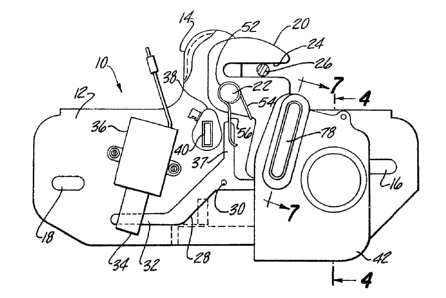
actuated rear deck lid lock mechanism 10 are shown in Figures 1
through 12. Referring first to Figure 1, the deck lid lock
mechanism 10 includes a support bracket 12 having an extension 14
protruding therefrom, and two mounting slots 16 and 18. As is
known in the art, the deck lid lock mechanism may be attached to
the vehicle's trunk lid or to a portion of the vehicle's frame
~ust below the trunk lid opening, depending upon the design of
the vehicle.
A latch member 20, shown in the locked position, is
- 5 -
. '
,' ~- -- '
: , -
~ '
1.2~7321A
pivotally connected to the horizontal support bracket 12 by means
of a first pivot pin 22. The latch member 20 has a laterally
offset catch slot 24 which is
.. 35
- 5a -
.
,~
- ' :
$273:2~4
located above the hori~ontal portion of the bracket 12 and captlvates d lock
bar 26 mounted on the rear deck lid when the latch member 20 is in the
locked position, as shown, preventing the rear deck lid from being raised.
A lock melnber 28 is pivotally connected to the bracket 12 by a
second pivot pin 30 and locks the latch member 20 in the locked position as
shall be explained with reference to Figure 2. A leg 32 of the lock member
28 is captivated in an actuator arm 34 of a solenoid 36 attached to the sup-
port bracket 12. The solenoid 36 is connected to the vehicle's power supply
through a switch (not shown) conveniently located in the vehicle's passenger
o B compartment. ~ cam 38 has an elongated slot 40 for receiving the
elongated extension bar of a manually key operated lock mechanism (not
shown,) such as is ordinarily provided on the vehicle for manually unlocking
the trunk lid. An elec~rical lock mechanism 42, which llas a cam actuated
electrical switch mechanism 78 as shown in Flgure 7, automatically returns
the latch member 20 to its locked position when the rear deck lid is lowered
sufficiently to trip the latch member 20 as shall be explained hereinafter.
Referring now to Figures 2 and 3, the electrical lock mechanism 42
is removed to show the details of the latch member 20 and the lock member
28. The lock member 28 has a second arm 44 extending generally normal to
a vertical arm 37. At the end of the second arm 44 ~s a dog 46 which enga-
ges a dog catch 48 provided at the extremity of a lower extension 50 of the
latch member 20. A coil spring 52, wound around the first pivot pin 22, has
a first leg 54 which engages the latch member 2~ below the first pivot pin
22 and produces a force which biases the latch member 20 to rotate ;n a
counterclockwise direction about the first pivot pin 22. A second leg 56 of
the coil spring 52 engages the vertical arm 37 of the lock member 28, pro-
ducing a force biasing the vertical arm 37 of the lock member 28 into enga-
gement with the cam 38 and the dog 46 into engagement with the dog ca~ch 48
of the latch member 20.
Rotation of the cqm 38 in a clockwise direction, as viewed 1n
Figure 2, by means of the manually key operated lock mechanism, or act~-
--6--
.
~7~2~4
vating the solenoid 36 to retract the actuator arm 3~, will rotate tlle lock
member 28 in a cl ockwi se direction di sen~agin~ the dog 46 from the dog catch
48 of the latch member 20. The coil spring 52, acting on the latch member
20, will cause the latch member to rotate in a counterclockwise direction to
that of the position shown in Figure 3. As shown in Fiyure 3, the lock bar
26 engages the lower surface of the catch slot 24 at a polnt laterally off-
set from the first pivot pin 22 such that a force applied to the latch
member 20 by the lock bar 2G will tend to rotate the latch n~mber 20 towards
the closed posi tion.
Cooperation of an external curved surface 58, opposite the dog 46,
and a curved surface 60, opposite the dog catch 48, will cause the lock
member 28 to be displaced against the force of the coil spring 52 when a
sufficient force is applied to the latch n~mber 20 urging ;t toward its
locked position. Once the dog catch 48 passes the dog 46, the force
opposing the coil spring 52 returns the latch member 28 to its locked posi-
tion with the vertical arm 37 engaging the surface of the cam 38 and the dog
46 engaging the dog catch 48 in order to lock the latch member 20 in its
locked position.
~eferring to Figure 4, the electrical lock mechanism includes a
housing 62 attached to the support bracket 12 with a plurality of screws
(not shown). Attached to the housing is a fractional horsepower electric
motor 64 which drives a cam gear 66 through a series of speed reproduction
gears, collectively designated as gear train 68.
A pair of diametrically opposed studs 70 and 72, attached to the
cam gear 66, protrude from the cam gear 66 and are operative upon rotation
thereof to engage the edge of the latch member 20 and return the latch
member 20 to its locked position. The two studs 70 and 72 are provlded on
the cam gear 66 so that the cam gear 66 only needs to rotate through one
-~ half of a revolution during each operating cycle. This reduces the time and
~0 electrical power required tl~o complete each locking cycle.
-7-
~;2732i.4
As shown ln Figure 5, the cam gear 66 also has a pair
of diametrically opposed accurate cam grooves 74 and 76 formed in
its upper surface lmmediately preceding each of the studs 70 and
72 in the control gear~s direction of rotation as shown by arrow
77 in Figure 5. The accurate cam grooves 74 and 76 cooperate
with the cam actuated electrical switch mechanism 78 embodied in
the housing 62 of the electrical lock mechanism 42 to lock and
rest the switch mechanism.
The details of the cam actuated electrical switch
mechanism 78 are shown in Figure 7. In Figure 7, the cam
actuated electrical switch mechanism 78 is shown in an open
state, which occurs after the locking cycle is completed, and
remains in this state until the rear deck lid is opened. Figure
9 through 11 show the state of the cam actuated electrical switch
mechanism 78 during sequential stages of the locking cycle.
Referring first to Figure 7, the cam actuated electrical switch
mechanism 78 includes a pair of spring contacts 80 and 82,
separated at one end by an insulating washer 84. One of the
spring contacts 80 and 82 ls connected to the vehicle's source of
electrical power, such as the vehicles battery, and the other
spring contact is connected to the electric motor 64. A collar
86 lnsulates a cap screw 88 and washer 90 from the spring
contacts 80 and 82. The cap screw 88 and the washer 90 clamp the
sprlng contacts 80 and 82 to a land 92 formed in the housing 62
at the bottom of an elongated cavity 94. Each of the spring
contacts 80 and 82 is dimpled to form a pair of opposing
electrical contacts 96 and 98, respectively. A cam follower 100
is provided in a first aperture 62a formed through the land 92
dlrectly above the path of the opposed arcuate grooves 74 and 76.
Flgure 7 shows the cam follower 100 ln the arcuate groove 74
formed in the top surface of the cam gear 66. The spring contact
80 produces a force urging the cam follower 100 to engage the
bottom of the accurate cam groove 74 when the spring contact BO
is lylng substantlally parallel to the surface of the land 92.
- 8 -
, ~ , .
,
. ~. .
~2`732~
As shown in Figure 9, a cylindrical post 102 is
attached at one end lOl to the end of the spring contact 82,
which is slidably received in a
.,
'
~ ,~
:,
- 8a -
~ ; .
, .
:",;
: ., ~ , . . . . , - . . -
: ~ . . .
; ' :
2~4
second aperture 62b ~n the land 92. In the open stat~ of the cam actuated
electrial switch mechanism 7~, the cylindrical post 102 is held in a raised
position by a leaf spring 104 engaging in lts rest position the other end of
the cylindrical post 102. The leaf spring 104 is held in position in the
housing by pressing it through a slit formed through a leg 108 of the
housing ~2, as shown in F~gure 7 and 8. Fi~ure 8 is a view of a portion of
the housing 62 directly below the cylindrical post 102.
As shown, the leaf spring 104, in its rest position, lies directly
beneath the cylindrical post 102 and is operatively displaced to the posi-
tion shown in phantom by the latch menlber 20 when the latch member 20 ~s in
its open position, as shown in Figure 3. With the leaf spring 104 ~-
displaced, as shown by the phantoln line of Figure 8, the cylindrical post
B ~ c~
102 is urged by the ~ 2 through the second aperture 62b in the
land 92 to engage the top surface of the latch member 20 as shown in Figure
9. In this position, the lower surface 102a of the cylindrical post 102 is
below the upper edge 104a of the leaf spring 104, thereby preventing the
leaf spring 104 from returning to its rest position when the latch member 20
is subsequently withdrawn from this positlon by the closing of the rear deck
lid. The electrical contacts 96 and 98 remain spatially separated when the
bottom of the cylindrical post 102 is resting on the top surface of the
latch member 20, as shown in Figure 9.
When the rear deck lid is closed, the lock bar 26 engages the
latch member 20 causing it to pivot in a clockwise direction about the
first pivot pin 22, displaclng the latch member 20 from below the cylindri-
ca1 post 102. This permits the spring contact 82 to displace the cylindri-
cal post 102 further down until the electrical contact 98 engages the
electrical contact 96, as shown in Figure 10. When the cylindrical post 102
is in its descended position, the latch member 20 is prevented from
returning to its full open position, as shown in Figure 3, resulting in the
lock bar 26 being entrapped in the catch slot 24 even though the rear deck
lid is not fully closed. Th~e engagement of the electrical contacts 96 and
g
.
.
12732~4
98 provides electrical power to the electric motor 64 which initiates the
rotation of the cam gear 66. As the cam gear 66 rotates, the cam follower
100 initially rides in the bottom of one of the cam grooves 74 or 76. At
the end of ~he cam groove 74 or 76 the cam follower 100 rises to the top
surface of the cam gear 66, as shown in Figure 11. The raising of the cam
B follower 100 out of the cam grooves 74 or 76 causes it to raise the spring
contacts 80 and 82 upwardly, as shown. During the raising of the spring
contacts 80 and 82, the electrical contacts 96 and 98 remain engaged with
each other and continue to supply electrical power to the electric motor 64.
sgc~. ;~ C l~ bc~
lU The raising of the ~ntoe~ hwJ~ 80 and 82 by the cam follower 100 riding
on the top surface of the cam gear 66 li~ts the cylindrical post 102 above
the upper edge 104a of the leaf spring 104 permitting the leaf spring 104 to
return to its rest position d~rectly below the lower surface 102a of the
cylindrical post 102. In this state of the cam actuated electrical switch
mechanism 78, the electr;c motor will continue to rotate the cam gear 66
until the next cam groove is encountered. When the next cam groove is
encountered, the cam follower 100 will descend into the next sequentlal cam
groove and the cam actuated electrical switch mechanism 78 ~ill return to
its initial state, as shown in Figure 7, terminating the supply of electri-
cal power by the electric motor 64 and, thereby, terminating the rotation of
the cam gear 66.
As previously indicated, the two studs 70 and 72, protruding from
the lower surface of the cam gear 66, engage the edge of the open latch
; member 20 and rotate the latch member in a clockwlse direction to its locked
position, entrapping the lock bar 26 ln the catch slot 24. This is more
clearly shown in Figure 12 in which the circle designated 110 defines the
.
external rotational path of the studs 70 and 72. In Figure 12, position "A"
desfgnates the posltion of the stud 70 when the cam actuated electrica~l
switch mechanism 78 is in its open position, as shown in Figure 7. When the
cam actuated electrical switch mechanism is c1Osed, the stud 70 will rotate
in a counterclockwise direction from position "A" and, after a predete~mined
10-
~ ~ .
: '~
.~; ~ ..
i2~ 4
rotation of the cam gear 66, will engage the edge of the latch member 20.
Continued rotation of the cam gear 66 to position "B" will displace the
latch member 20 towards its locked position a distance sufficient to cause
the dog 46 of the lock member 28 to engage the dog catch 48 of the latch
member 20, as shown ~n phantom, securing the latch member 20 In its locked
position. After the latch member 20 is secured in its locked position, the
cam gear 66 will continue to rotate disengaging the stud 70 from the latch
member 20. The cam gear 66 will continue to rotate until the cam follower
100 of the cam actuated electrical swltch mechanism 78 encounters the cam
groove 76 associated with the diametrically opposed stud 72 where the
electrical contacts 96 and 98 separate, as shown in Figure 7. The separa-
tion of the electrical co;ntacts 96 and 98 causes the motor to stop with the
stud 70 at position "C", which is d;ametrically opposite to its starting
position "A".
The operation of the rear deck lid lock mechanism is as follows:
When it is desired to open the rear deck lid, the operator
may either activate the solenoid 36 from a remote location inside of the
vehicle or may rotate the cam 3~ by means of the manual key operated lock
mechanism. Activating the solenoid 36 or rotating the cam 38 rotates the
lock member 28 in a clockwise direction, as viewed in Figures 2 and 3,
disengaging the dog 46 from the dog catch 48, allowing the coil spring 52 to
rotate the latch member 20 to its open position. With the opening of the
latch member 20, the lock bar 26tdisplaced upwardly slightly raising the
deck lid. The lock bar 26 is now clear of the catch slot 24, permitting the
rear deck lid to be raised manually or under the influence of biasing means
(not shown). If the rear deck lid is spring-loaded, it will automatically
rise to its fully open poslt~on. The opening of the latch member 20 a~so
displaces the vertical leaf spring 104 permitting the cylindrical post 102
- to descend and engage the top surface of the latch member 20, setting the
3~ electrical locking mechanis~ for lts closing cycle.
.
:' ~.' ' '- .
. .
1273Z~4
The rear deck lid may be closed by either of two methods. First,
the deck lid may be closed in the convent~onal manner by applying a force
sufficlent for the lock bar 26 to rotate the latch n~mber 20 to its locked
position with the dog 46 engaging the dog catch 48. In the alternative, the
deck lid may be locked only using a force sufficient to displace the latch
member 20 away ~rom under the cylindrical post 102 which causes the contacts
96 and 98 of the cam actuated electrical switch mechanism 78 to close and
energize the electric motor 64. The electric motor will then drive the cam
gear 66 and the stud 70 or 72 w;ll d;splace the latch member 20 to its
locked position as previously described, locking the deck lid in its closed
position.
An alternate embodiment of the electrically actuated rear deck
lock mechanlsm is shown ~n F~gure 13. This alternate embodiment ~s func-
tionally similar to the first embodiment shown in Figure 1, however, the
requirement for a solenoid, such as the solenoid 36, to unlatch the lock
mechanisln has been eliminated and an electrical bypass cam has been added.
Referring to Figutlt13, the lock mechanism has a support bracket 112
B corresponding totsupport bracket 12 of the first embodiment and includes a
latch member 120 corresponding to the latch member 20 and a bypass cam 210.
The latch member 120 and bypass cam are p~votally connected to the support
bracket 112 by means of a first pivot pin 122. The latch member 120 has a
laterally offset catch slot 124 which captivates the vehicle's lock bar 26
as prev;ously described and a raised dog 125 which engages an edge of the
bypass cam 210.
~: 25 A lock member 128 is pivotally connected to the bracket 112 by a
second pivot pin 130 and locks the latch member 120 in its locked position
as previously described. A vertical arm 137 of the lock member 128 engages
the surface of a key actuated cam 138 rotatably attached to the suppo~t
bracket 112 as more clearly shown in Figure 14. The cam 138 has a slot 140
for receiving the extension bar of a manually operated lock mechanism (not
shown), such as is normally prov;ded for manually unlocking the rear deck
-12-
,
127~2~A
lid lock l~chanism. The key actuated Cdlll 13~ also has a ralnp surface 139 as
shown in Fiyures 2~ and 25 wh;ch lifts the bypass cam 21~ disengaging it
~roin t~e latch melllber s dog 125, as s~lall be explained hereinafter. An
electrical lock actuator 142 which has an electric motor 164 and a cam
actuated single pole double throw switcn mechanism 178 automdtically
returns the latch melllber 12~ to its locked position as previously described
with reference to the first embodiment and will unlatch the lock mechanism
in response to the yeneration of an elèctrical unlatch signal.
Referring now to Figures 14 and 15 the electrical lock actuator
142 is removed to show the details of the latch member 120 bypass cam 210
and lock melnber 128. The lock n~mber 128 has a second arm 144 extending
generally normal to the vertical arm 137. A doy 146 provided at an inter-
mediate location along the second arm 144 is engaged by a dog catch 148 pro-
vided at the extremity of t~le latch l~mber 120. A coil spring 152
circumscribing the first pivot pin 122 biases the bypass cam 210 to rotate
~LS~ ~)) ~6~j,
in d counterclockwise direction about the first pivot pin 122 and~the lock
member 128 into engagement with the cam 138. In the locked position of the
lock mechanis~ the dog 146 engages the dog catch 14~as shown e~ Figure 14
and as previously described with reference to the first embodiment. The
2~ coiT spring 152 also produces a force biasing the bypass cam 210 towards the
latch menlber 120. The bypass cam 210 has a tab 212 whicll engages the mating
edge of latch melllber 120 so that the latch l~mber 120 is forced to rotate
with the bypass cam 210 in tne counterclockwise direction. A second spring
153 independently biases the latch rnember 1?0 towards the unlocked position.
Unlatching of the dog catch 148 from the dog 146 may be
accomplished mechanically by the manual rotation of the key actuated cam 138
by a key inserted in the rear deck lid lock or electrically as shall be
explained hereinafter. The locking function of the alternate embodiment is
similar to that previously described with reference to the first embodiment.
The details of~the electrical lock actuator 142 are shown in
-13-
:
.
~273~14
Figure 16. Referring now to Figure 16 the electrical lock actuator 142
includes a housing 162 which is attached to the support bracket 12 by a
plurality of screws (not shown). Attached to the housing 162 is a frac-
tional horsepower electr;cal motor 164 which drives a cam gear 166 through a
gear train 168.
A pair of diametrically opposed studs 170 and 172 protrude from
the cam gear 166 and are operative upon rotation of the cam gear 166 to
engage the edge of the bypass cam 210 and return the latch ~ember 120 to its
latched position and upon further rotation to engage the end of the lock
member's second arm 144 releasing the latch member's dog catch 148 from the
dog 146. As in the f;rst embodiment, the two diametrically opposed studs
170 and 172 are provided so that the cam gear needs to rotate only through a
half of a revolution for each complete operational cycle.
As sllown in Figures 17 and 18, the cam gear 166 has a pair of
diametrically opposed arcuate cam grooves 174 and 176 provided in its upper
surface immediately preceding each of the studs 170 and 172 in the direction
of rotation indicated by arrow 177. As shown in greater detail in Figure
18, both of the cam grooves 174 and 176 are bi-level sucll that the leading
sections 173, are deeper than the trailiny sections 175. The bi-level
yrooves 174 and 176 cooperate with the switch mechanism 178 embodied in the
housing 162 to lock or release the latch member 120.
In Figure 16, the electrical lock actuator 142 is shown with the
lock mechanism in its locked state with the stud 170 in the position "A" as
illustrated ~ Figure 15. In this position a cam follower 200 is in the
deepest section, section 173, of ~he cam groove 174 or 176 and the center
spring contact 181 is in electrical contact with t~ lower spring contact
180. The center spring contact 181 is connected to the motor 164, as ~hown
in Figure 19, while the lower spring contact 180 is connected to the source
of electr;cal power 183 through an unlock switch 185. The spring contact
-14-
~2~ 1A
181 produc~s a force on th~ cam follower 200 causing it to follow th~ Con-
tour c~ the car,l gear 166. A post 202, which is sli~bly received in an
aperture in the housing 162, is attached at one end to a third contact
spring 182. In the locked state, the post 202 is held in an elevated posi-
B tion by a post lock which may be a spring,\as the leaf spring 104
illustrated in Fiyure 8,or a post bar 204 biased by a spring 203 as
illustrated in Figure 20. The post bar 204 is functionally the same as the
leaf spring 104 and holds the post 202 in its highest elevated position when
the lock mechanism is in its locked state. In the highest elevated position
of the post 202, the spring contact 182 is disengaged from the spring con-
tact 181. The post bar 204 is displaced from under the post 202 by the
bypass cam 210 when the lock mechanism is unlatched, permitting the post 202
to descend to an intermediate level which prevents the post bar 204 from
assuming a position under the post 202 untll the post 202 is again raised to
its highest elevated position by the cam follower 2U0 acting on the spring
contact 182. The spring contact 182 produces a force on the post 202,
: urging it downward to its lowest permitted level.
Referring now to Figure 19, when the unlock switch is depressed,
the motor 164 is energized through the electrical contact between the spring
contacts 180 and 181 which causes the cam gear to rotate displacing the stud
170 from position "Al' to position "B", as shown in Figure 15. During this
~1 ~56~,c, ~
rotation, the stud 170 engages the end of the lock member's~arm 144
disengaging the dog 146 from the dog catch 148, and releasing the latch
member 120. The latch member 120 and bypass cam 210, biased by the coil
spring 152 and spring 153, will rotate to the open position as shown in
Figure 15.
When the stud 170 reaches position "B", the cam follower 200~rlses
up in the upper level section 175 of the arcuate bi-level groove 174 or 176
which displaces the spring contact 181 upward a distance sufficient to break
the electrical contact betweèn the spring contacts 180 and 181 but not high
enough to make electrical contact between the spring contacts 181 and 182,
-15-
as sho~n in Fi~ure 21. In this state, electrical power to the motor 164 is
terminlted, causing the cam gear 166 to stop with the stud 170 in position
"B" and the stud 172 in position "C".
The lock næchanism will remain in this state until an attempt is
matle to close the rear deck lid. As discussed with reference to the first
embodiment, when the rear deck lid is closed sufficiently to displace the
latch member 120 and the bypass cam 210 from under the post 202, the post
202 will descend under the bias of the spring contact 182, and the spring
contact 182 will make electrical contact with the spring contact 181, as
shown ln Figure 22. Electrical contact of the spring contact 182 with the
spring contact 181 wlll provide electrical power to the motor 164 and therby
rotate the stud 172 from position "C" to position "A", as shown in Figure
15. The stud 172 will engage the e~ge of the bypass cam 210 and rotate it
in a clockwise direction. The edge 214 of the bypass cam 210 will engage
the latch member's raised dog 12~ and rotate the latch member 120 along with
the bypass cam 210 towards the latched position. At the position "D" the
stud 172 will have rotated the bypass cam 210 and latch member 120 a
distance sufflcient to cause the dog 146 to engage the dog catch 148,
locking the latch member 120 in the latched position. As the cam gear 166
is being rotated, the cam follower 200 will rise out of the cam groove 174
or 176, raising both spring contacts 181 and 182 to their maximum heights,
as shown in Figure 23. ~he spring contact 182 will elevate the post 202 to
a height sufficient to permit the post bar 204 to be displaced under the
post 202 by the spring 203 thereby holding the post 202 in its elevated
position. When the stud 172 reaches position "A", the cam follower 200 will
fall in the section 173 of the next cam groove, returning the switch mecha-
nism 178 to the state shown in Figure 16, which is the latched state of the
lock mechanism.
, .
If the latch member 120 is released by manually rotating the cam
138 by means of the key lock~, the bypass cam 210 will displace the post bar
204 such that when the rear deck lid is closed sufficiently to displace the
- -16-
1273214
bypass c~m 210 from under the post 202, the post 202 will descelld permitting
the spriny contact 182 to rnake electrical contact with the spring contact
181 and energizing the motor 164 to lock the latch member 120 in the dog
146, as previously described. If the rear deck lid is slalluned down hard
~ enough to lock the latch member 120 in the doy 146, the ~ost 202 will
descendJenergizing the Inotor which will continue to run until tne stud 170
B or 172 assumes position "A", as shown in Fiyure 15.
If the latch D~mber 120 is released from the doy 146 but the rear
deck lid does not open due an accumulated weight, such as a heavy snow, the
motor will drive the cam gear 166 until the stud 170 or 172 reaches position
"A" and then will stop. The bypass cam will not have moved far enough to
displace the post bar 204; therefore, the spriny contact 181 remains
separated froln the spring contact 180 by the caln follower. To activate the
lock mechanislll, the rear deck lid must be lifted a distance sufficient to
cause the bypass cam 210 to displace the post bar 2~4. This prevents con-
tinuous recycling of the lock mechanism when the rear deck lid does not open
after the latch nlember 120 is released.
The function of the bypass cam 210 will be explained with
reference to Figures 15, 26, 27, and 28. The bypass cam 210 is rotatably
connected to the latch member 120 by means of the raised dog 125 and the tab
212, so that the two will pivot together about the pivot pin 122 as shown on
Figures 15 and 26. The coil sprlng 152 produces a force biasing the bypass
cam 210 towards the latch member 120 so that the raised dog 125 will engage
the edge of the bypass cam 210 as shown in Figure 26.
As illustrated in Figure 15, if there is an electrical failure or
a failure of the electrical lock actuator 142 which results in the cam gear
166 stopping with one of the studs 170 or 172 in the position designated
"D", or any other nearby position, the stud will prohibit the bypass cam 210
from rotating to the unla~ched position shown. Under this condition, the
latch member 120 may still be released to the unlatched position by rotating
the key actuated ca0 138 to the position shown in Figure 28. In this posi-
-17-
~2732~4
tion, the ramp surface 139 of the key actuated cam 138 will lift
the bypass cam 210 above the upper surface of the dog 125, as
shown in Figure 27. The rotation of the key actuated cam 138
will also displace the lock member 128, releasing the latch
member 120 from the dog 146. With the bypass cam 210 in the
raised position, the latch member~s dog 125 is disengaged and the
latch member 120 is free to rotate to the unlatched position,
independently of the bypass cam 210, as shown in Figure 28. AS
previously indicated, the latch member 120 is independently
blased by the spring 153 to rotate to the unlatched position.
Therefore, when the rotatlon of the bypass cam 210 to the
unlatched position is prohibited by one of the studs 170 or 172,
the electrically actuated lock mechanism may still be manually
unlocked using the conventional key lock.
One advantage of the rear deck lid lock mechanism is
that the locking of the rear deck lld ln lts closed posltion ls
assured, lndependent of the closing force. Another advantage of
the rear deck lld lock mechanism is that the deck lld does not
have to be slammed down to set the latch member ln its locked
posltlon. Still another advantage of the rear deck lid lock
mechanlsm ls that the deck lld may be locked mechanically or
electrically. A further advantage is that once the latch member
` is in the locked position, the electrical locking mechanisms
disengaged from the latch member and all subsequent forces
applied to the deck lid are sustained by the mechanical elements
of the lock and not by any of the components ln the electrlcal
locklng mechanlsm. Still another advantage of the lock mechanlsm
is that is may be manually unlatched using the conventional key
lock in the event of an electrical failure.
::
:
- 18 -
::
~"
,
,
.