Note: Descriptions are shown in the official language in which they were submitted.
-- 1 --
This invention relates to an improved pre-pasted
wallpaper trough assembly having a thin wall plastic tray and
two roller bars.
In the prior art, for example ~cCURDY in U.S.A. patent
4,244,320 issued 13 January, 1981, discloses a Wallpaper
Trough Assembly submerging in water a wetting rod fixedly in
the trough and directing the pre-pasted roll or partial
wallpaper to travel underneath the rod and thus through the
water in the trough before exiting. The wallpaper roll rests,
in part, against the wetting bar and also against the side
wall of the trough and the wallpaper travels underneath the
rod. As the thickness of the wallpaper roll diminishes, the
wallpaper roll falls to the bottom of the trough 12 and wedges
itself between the wetting rod 14 and bottom and wallpaper
travel is impeded.
When cut lengths of pre-pasted wallpaper are put in this
trough they also wedge themselves, inevitably, between the
horizontal wetting rod 1~ and bottom and complete wetting of
the paper i5 never easily achieved.
Reid et al in U.S.A. patent 2,~98,883 issued 11 October,
1959, discloses an Apparatus for Wetting a Roll of Pre-pasted
Wall Paper wherein the total roll is submerged and carried in
part by a hanger. In a variation thereof the roll is
positioned on a hanger above the water level to pass through
the water and under a "u-shaped" rack having a wetting bar
portion which ensures wetting. Travel of the paper through
the water in both variants is impeded because of use of wire
hangers and the paper binds.
Though both of these prior art references were intended
to pre-wet pre-pasted wallpaper when on a single roll, they
address the issue poorly and do not address the need of
pre-wetting strips of pre-pasted wallpaper which have been cut
to specific lengths prior to the wetting.
It is an objective of the invention to provide a water
trough which, on the one hand, holds an elevated roll of
wallpaper above the water line in the trough but allows the
wallpaper, to be rolled off the roll through the water in the
.
2--
trough under a wetting bar and to be easily pulled and managed
thereby and to be subsequently cut as required.
It is a further object of the invention to provide two
bars, a fixed wetting bar or rod mounted in the water under
which the wallpaper travels so as to ensure wetting and
another paper holding, a movable bar that at a first paper
roll carrying station carries a roll of wallpaper at an
elevation above the water level so as to allow the wallpaper
to travel, when pulled, into and through the water underneath
the wetting rod and thence to exit from the water trough.
It is also an object to the invention to provide means
to locate the movable paper holding rod at a second station
that is at an elevation below the water level in the trough so
as to allow pre-cut lengths of pre-pasted pre-cut wallpaper to
be rolled from the second station while submerged within the
water trough under the wetting rod so that the cut length may
bè removed in a wet condition from the trough.
The invention therefore contemplates a wallpaper trough
comprising:
(a~ a first fixed rod and a second movable rod, each
with ends
(b) a preformed flexible unitary container including a
longitudinal backside, bottom, and front side having an
essentially vertical lower segment stepping through an
inter~ace into an outwardly projecting inclined upper
segment, and opposite ends, the ends adapted to carry
the fixed rod at an elevation between the bottom and
interface, and means to provide a first station for
holding the movable rod at an elevation above the
interface and a second station ~or holding the movable
rod at an elevation below the interface.
The invention will now be described by way of example
and reference to the accompanying drawings in which:
Figure 1 is a perspective view of the invention;
Figure 2A is a section along line II-II of figure 1 with
the movable rod is located in its first station;
.. ....
-- 3 --
Figure 2B is a section along II-II of figure 1 ~7ith the
movable rod located in its second station position.
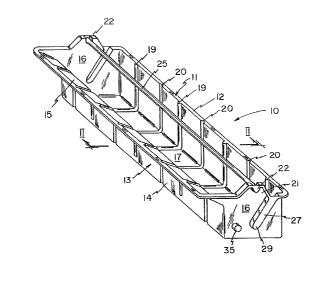
Referring to figure 1, A wallpaper water trough is
generally shown as 10 and includes a pre-formed Elexible
polystyrene container 11 with essentially one vertical side
wall 12, an opposite side wall 13 having a lower vertical
segment 14 and an upper inclined segment 15, and opposite
complimentary end walls 16 all integrally moulded with an
essentially flat and unitary bottom 17.
Since the container 11 is thin walled in order to add
rigidity integrally moulded therewith are lateral ribs
generally indicated as 19 and 20. The ribs 19 are inwardly
protruding while ribs 20 are outwardly protruding and appear
from the interior of the container as lateral recesses.
Each end wall 16 has an upper upright portion of 21
centered along its upper margin with an arcuate recess 22
therein that establishes a first wallpaper holding station 22
for a movable wallpaper carrying rod or bar 25. This rod 25
carries a roll of wallpaper 30.
The end walls 16 are also moulded so as to define an
angulated slot 27 whose bottom 29 at opposite ends is at an
elevation which will be below the water line in the trough.
The water line generally is located at or slightly below
the interface between the vertical segment 14 and the
angulated segment 15 of the front wall 13 as seen in figure 2.
A fixed wetting rod or bar 40 is fixedly positioned at
an elevation slightly below the bottom 29 of the slot 27 and
this rod 40 is the wetting bar underneath which the wallpaper
30 travels as seen in figures 2A and 2B. In that respect each
end wall 16 has a cylindrical recess 35 that protrudes beyond
the outside surface of the end 16 and accomodates opposite
ends of the fixed wetting rod 40 so that the ends of the rod
,40 nest in -the recess formed by the cylindrical protrusions
35. The rod 40, if fabricated from polystyrene or even wood,
and because of the length of the trough is approximately
24" ~60cm) or more, the natural flex in a rod allows it to be
-- 4 --
relatively easily inserted into the recesses 35 so as to hold
the wetting rod 40 rigid in its fixed position while still
allowing that rod to be removed for cleaning of the trough.
Referring to figure 2A the arrows indicate how the
wallpaper is rolled off from the first s~tation 22 through the
water W in the trough, underneath the Eixed rod 40, and
exiting in the manner shown.
When pre-cut sheets of the roll of wallpaper are put on
the movable paper holding rod 25 and that rod 25 is placed
into the second station 29, as shown in the cros~ sectional
figure 2B, the individual sheet of wallpaper is passed under
the fixed rod 40 and pulled in accordance with the arrow
shown, no paper binding occurs.