Language selection

Search

Patent 1273383 Summary

Third-party information liability

Some of the information on this Web page has been provided by external sources. The Government of Canada is not responsible for the accuracy, reliability or currency of the information supplied by external sources. Users wishing to rely upon this information should consult directly with the source of the information. Content provided by external sources is not subject to official languages, privacy and accessibility requirements.

Claims and Abstract availability

Any discrepancies in the text and image of the Claims and Abstract are due to differing posting times. Text of the Claims and Abstract are posted:

  • At the time the application is open to public inspection;
  • At the time of issue of the patent (grant).
(12) Patent: (11) CA 1273383
(21) Application Number: 514732
(54) English Title: DEFOGGING AND DEICING SHIELD STRUCTURE
(54) French Title: ECRAN A ELEMENT DE DESEMBUAGE ET DEGIVRAGE
Status: Deemed expired
Bibliographic Data
(52) Canadian Patent Classification (CPC):
  • 309/5
  • 2/72
  • 2/80
(51) International Patent Classification (IPC):
  • H05B 3/26 (2006.01)
  • A42B 3/24 (2006.01)
  • A61F 9/02 (2006.01)
(72) Inventors :
  • HOLLANDER, JAMES M. (United States of America)
(73) Owners :
  • HOLLANDER, JAMES M. (United States of America)
(71) Applicants :
(74) Agent: SWABEY OGILVY RENAULT
(74) Associate agent:
(45) Issued: 1990-08-28
(22) Filed Date: 1986-07-25
Availability of licence: N/A
(25) Language of filing: English

Patent Cooperation Treaty (PCT): No

(30) Application Priority Data:
Application No. Country/Territory Date
853,169 United States of America 1986-04-17

Abstracts

English Abstract


ABSTRACT OF THE DISCLOSURE


An improved defogging and deicing shield structure
suitable for use as a face shield in combination with a
protective helmet or for use in goggles comprising at
least two spaced coextensive lenses. The inner surface
of one lens is imprinted with an electrical circuit in a
predetermined pattern. The resistance of the circuit
being sufficient to generate heat effective to defog or
deice the exterior surface of the other lens when the
circuit is connected to a direct current power source.


Claims

Note: Claims are shown in the official language in which they were submitted.


The embodiments of the invention in which an exclu-
sive property or privilege is claimed are defined as
follows:
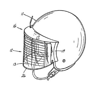
1. In a protective helmet and face shield
assembly including fastener means for securing the
shield releasably to the helmet and hinge means
between the fastener means and the shield permitting
relative motion between the shield and the helmet an
improved face shield comprising:
at least two spaced, plastic lenses provid-
ing a field of view, one lens defining a face lens
and another lens defining a weather lens, a surface
of one of said lenses being printed with an electri-
cally conductive circuit of an ink having a metallic
content substantially throughout said field of view,
said circuit being arranged upon said surface in
accordance with a pattern of spaced, continuous,
generally parallel lines, said lines a-t maximum width
and minimum spacing occupying no more than about
eight percent (8%), per unit area, of said field of
view, said circuit having sufficient electrical
resistance to create heat effective to inhibit
formation of fog, ice or frost upon the face shield,
and said pattern of lines being effective to provide
maximum light transmission and visibility there-
between through said shield.

2. The assembly of claim 1, in which the
lenses are coextensive and the region between the
spaced lenses defined an air space.

3. The assembly of claim 1, in which the
circuit is printed upon an inner surface of one of
said lenses.

11

4. The assembly of claim 3, in which the
circuit is printed upon the inner surface of the face
lens.

5. The assembly of claim 2, in which the
periphery of the coextensive lenses is provided with
seal means protecting the air space against undesir-
able exterior fluid and particulate matter.

6. The assembly of claim 5, in which the seal
means includes an elongated peripheral spacer formed
integrally with one of said lenses.

7. The assembly of claim 6, in which the seal
means comprises a combination of said spacer and a
suitable adhesive or bonding agent.

8. The assembly of claim 4, in which the
printed electrical circuit develops sufficient
resistance to electrical current to create heat in
said air space.

9. The assembly of claim 8, in which the
printed circuit develops a power density throughout
said one of said lenses when energized by a 12 volt
a.c. or d.c. power source effective to create heat
sufficient to eliminate fog or mist and to melt snow,
ice, slush and the like accumulating on the outer
surface of the weather lens.

12


10. The assembly of claim 9, in which the
material from which the lenses are fabricated and the
power density are selected to optimize defogging and
deicing without deleterious effect upon the lens
material.


11. The assembly of claim 9, in which the
power density ranges from 0.30 to 0.60 watts per
square inch of face lens within said circuit pattern.


12. The assembly of claim 11, in which the
material from which the face lens is manufactured is
selected from the group consisting of polycarbonates,
butyrate and acrylics.


13. The assembly of claim 1, in which the
printed circuit includes opposed bus bars each
connected to an insulated electrical conductor and
the conductors lead to an a.c. or a d.c. power source.


14. The assembly of claim 2, in which the air
space defines a thermal insulator blocking excessive
heat loss through the weather lens and minimizing
power consumption.

13


15. The assembly of claim 13, in which one
insulated conductor is replaced partially by an
extension of one bus bar.

16. The assembly of claim 1, in which a portion
of the pattern includes spaced parallel lines having
a width ranging from 0.010 to 0.030 inches, a thick-
ness less than 0.0005 inches and which are spaced
apart a distance ranging from .375 to 1.00 inches
measured from the center of each line.

17. A face shield comprising at least two
plastic lenses providing a field of view, one lens
defining a face lens and another lens defining a
weather lens, said lenses being coextensive and being
separated by spacer means defining an appreciable air
gap between lenses, the inner surface of one lens
being printed with an electrically conductive circuit
of an ink having a metallic content arranged in
accordance with a predetermined pattern, said pattern
defining spaced parallel lines or ribbons of printed
indicia where the lines range in width from 0.010 to
0.030 inches and in thickness less than 0.0005 inches
and are spaced apart a distance ranging from 0.375 to
1.00 inches measured from the center of each line or
ribbon, said lines at maximum width and minimum
spacing occupying no more than about eight percent
(8%), per unit area, of said field of view.

18. The face shield of claim 17, in which the
spacer means defines a peripheral bead formed
integrally with said weather lens.
14


19. The face shield of claim 18, in which portions
of the perimeter of said coextensive lenses are air closed
by seal means protecting the inner surfaces of the lenses
against entry of undesirable particulate and fluid matter.


20. The face shield of claim 17, in which the weather
lens is of a thickness ranging from 0.050 to 0.100 inches
and the face lens is of a -thickness ranging from 0.020 -to
0.040 inches.


21. The face shield of claim 17, in which the lenses
are spaced apart a distance ranging from 0.050 to 0.250
inches.


22. The face shield of claim 21, in which the weather
lens is of a thickness ranging from 0.050 to 0.100 inches
and the face lens is of a thickness ranging from 0.020 to
0.040 inches.


23. The face shield of claim 17, 20 or 21, in which
the lens printed with said circuit is said face lens.


24. The face shield of claim 18 or 19, in which the
lens printed with said circuit is said face lens.


25. A face shield of claim 17, 20 or 21, in
which the lens printed with said circuit is said
face lens and said circuit has sufficient electrical
resistance to warm said air gap and said weather and
face lenses to keep said face lens free of fogging
and inhibit formation of fog, ice or frost
on said weather lens.


26. A face shield of claim 18 or 19, in which
the lens printed with said circuit is said face
lens and said circuit has sufficient electrical
resistance to warm said air gap and said weather and
face lenses to keep said face lens free of fogging
and inhibit formation of fog, ice or frost on said
weather lens.


27. The face shield of claim 17 or 21, in
which the lens printed with said circuit is said
face lens and said circuit has sufficient electrical
resistance to warm said air gap and said weather and
face lenses to keep said face lens free of fogging
and inhibit formation of fog, ice or frost on said
weather lens; said weather lens having a thickness
ranging from 0.05 to 0.100 inches, and said face
lens having a thickness ranging from 0.020 to
0.040 inches.
16


28. The face shield of claim 18 or 19, in which
the lens printed with said circuit is said face lens
and said circuit has sufficient electrical resistance
to warm said air gap and said weather and face lenses
to keep said face lens free of fogging and inhibit
formation of fog, ice or frost on said weather lens;
said weather lens having a thickness ranging from
0.05 to 0.100 inches, and said face lens having a
thickness ranging from 0.30 to 0.040 inches.

29. A defogging and deicing shield structure in
the form of goggles comprising at least two plastic
lenses providing a field of view, defining an eye
lens and a weather lens, spacer means for creating an
air gap between lenses, an electrically conductive
circuit of an ink having a metallic content printed
on an inner surface of said eye lens effective to
warm said air space and said weather lens when said
circuit is connected to a 12 volt course of a.c. or
d.c. current to inhibit formation of fog, ice or
frost upon said weather lens, said circuit defining
space parallel lines or ribbons of printed indicia
where the lines range in width from 0.010 to 0.030
inches and in thickness less than 0.0005 inches and
are spaced apart a distance ranging from 0.375 to
1.00 inches measured from the centre of each line or
ribbon, said lines at maximum width and minimum
spacing occupying no more than about eight percent
(8%), per unit are, of said field of view.

30. In a protective helmet and face shield
assembly including fastener means for securing the
shield releasably to the helmet and hinge means
between the fastener means and the shield permitting
relative motion between the shield and the helmet an
improved face shield comprising:

17

at least two spaced, plastic lenses provid-
ing a field of view, one lens defining a face lens
and another lens defining a weather lens, a surface
of one of said lenses being printed solely by silk
screening with an electrically conductive circuit of
an ink having a metallic content, substantially
throughout said field of view, said circuit being
arranged upon said surface in accordance with a
pattern of spaced, continuous, generally parallel
lines, said lines at maximum width and minimum
spacing occupying no more than eight percent (8%),
per unit area, of said field of view, said circuit
having sufficient electrical resistance to create
heat effective to inhibit formation of fog, ice or
frost upon the face shield, and said pattern of lines
being effective to provide maximum light transmission
and visibility therebetween through said shield.

31. The assembly of claim 30, wherein said
field of view is otherwise free of coatings or films.

32. The assembly of claim 30, in which the
lenses are coextensive and the region between the
spaced lenses defines an air space.

33. The assembly of claim 32, in which the air
space defines a thermal insulator blocking excessive
heat loss through the weater lens and minimizing
power consumption.

34. The assembly of claim 32, in which the
periphery of the coextensive lenses is provided with
seal means protecting the air space against undesir-
able exterior fluid and particulate matter.

18


35. The assembly of claim 34, in which the seal
means includes an elongated peripheral spacer formed
integrally with one of said lenses.


36. The assembly of claim 35, in which the seal
means comprises a combination of said spacer and a
suitable adhesive or bonding agent.


37. The assembly of claim 30, in which the
circuit is printed upon an inner surface of one of
said lenses.


38. The assembly of claim 37, in which the
circuit is printed upon the inner surface of the
face lens.


39. The assembly of claim 38, in which the
printed electrical circuit develops sufficient
resistance to electrical current to create heat in
said air space.


40. The assembly of claim 39, in which the
printed circuit develops a power density when
energized by a 12 volt a.c. or d.c. power source
effective to create heat sufficient to eliminate
fog or mist and to melt snow, ice, slush and the
like accumulating on the outer surface of the
weather lens.

19


41. The assembly of claim 40, in which the
material from which the lenses are fabricated and
the power density are selected to optimize defogging
and deicing without deleterious effect upon the lens
material.


42. The assembly of claim 40, in which the
power density ranges from 0.3 to 0.60 watts per
square inch of face lens within said circuit pattern.


43. The assembly of claim 42, in which the
material from which the face lens is manufactured is
selected from the group consisting of polycarbonates,
butyrates and acrylics.

44. The assembly of claim 30, in which the
printed circuit includes opposed bus bars each
connected to an insulated electrical conductor and
the conductors lead to an a.c. or a d.c. power
source.


45. The assembly of claim 44, in which one
insulated conductor is replaced partially by an
extension of one bus bar.


46. The assembly of claim 30, in which a portion
of the pattern includes spaced parallel lines having
a width ranging from 0.010 to 0.030 inches, a thick-


ness less than 0.0005 inches and are spaced apart a
distance ranging from 0.375 to 1.00 inches measured
from the center of each line.

47. The face shield of claim 30 or 46, in which
the weather lens is of a thickness ranging from 0.050
to 0.100 inches and the face lens is of a thickness
ranging from 0.020 to 0.040 inches.

48. A face shield of claim 17, in which the
lens printed with said circuit is said face lens.

49. A face shield of claim 48, in which said
circuit has sufficient electrical resistance to warm
said air gap and said weather and face lenses to keep
said face lens free of fogging and inhibit formation
of fog, ice or frost on said weather lens.

21

Description

Note: Descriptions are shown in the official language in which they were submitted.


```` ~7;~


BACKGROUND OF THE INVENTION
The present invention rela~es to shield structures
and relates, in particular, to such structures which are
useful in combination with a protective helmet or in
goggles including means incorporated in the shield for
effecting a defogging or a deicing function.


- PRIOR ART
Prior art shield structures are disclosed and
described in U.S. Patent ~os. 3,024,341 issued March 6,
1962 to Ogle et al. entitled Hea~ed Face Plate For

,
Pilot's Helmet, 3,727,235 issued April 17, 1973 to
Fisher entitled Retractable Face Protective Assembly and
4,575,875 issued March 18, 1986 to Dawson et al.
entitled Detachable Visor For A Motorcycle Helmet.
The '341 patent discloses an elec~rically
conductive transparent film deposited on a transparent
visor of an aircraft halmet. Alternatively, the film is
sandwiched between two transparent laminated sheets.


The '235 patent shows a single lens shield which
is releasably attached to a helmet and includes means
for effecting relative motion between the shield and
the helmet. As is most apparent in Figs. 19 and 20
the shield includes a defogging means 426 comprising
air flow directing panel means 450.
The '875 patent shows a detectable visor 10
having a recess 32 facilitating attachment of the
visor to the helmet. The recess is then filled with
a panel 40. An air flow deflector panel 50 is
attached to the underside of the visor.
- While electrically conductive films are operative
to defog aircraft helmets the films usually create a
tinting effect reducing light transmission with some
reduction in visibility. Without doubt, these losses
present no problem and, in fact, are probably an aid
to a flyer ranging high above clouds where one needs
protection from the bright sun.
In contrast, shield requirements in surface
applications including night operations require maxi-
mum light transmission with maximum visibility.
Consequently, the present invention
seeks to provide a shield structure useful


~ 73~

in combination with a helmet or in goggles which
inhibits the formation of fog, ice or frost upon the
shield while providing maximum light transmission and
maximum visibility, day and night.
A further feature of the invention is the pro-
vision of a shield structure comprising at least two
lenses spaced apart by an air gap.
further feature of the invention is the pro-
vision of multi-lens shield structure or device in
which the inner face of one lens is imprinted with an
electrically conductive circuit arranged in a pre-
determined pattern to provide maximum light trans-
mission and good visibility to the user.

A still further feature of the invention is the
provision of a shield device having a relatively heavy
gauge weather lens spaced from a relatively light gauge
` face lens.
A further feature of the invention is the pro-

vision of a printed electrically conductive circuit onthe inner surface of the face lens.
A still further feature of the invention is the
provision of a thermal insulating barrier in the form
of a gap between the face lens and the wather lens to
minimize heat loss through the weather lens.


~ _


.
: .

~'~7~
_
~6-154


A shield structure for defogging, deicing, and
defrosting embracing certain features of the present
invention may comprise at least two spaced lenses one
lens defining a face lens and another lens defining a
weather lens one of said lenses being imprinted, with an
electrically conductive circuit, said circuit being
arranged upon said lens in accordance with a
predetermined pattern.
The term "lens" is intended to denote sheets or
plates of relatively flexible, highly transparent
material having planar or curved surfaces usually
fabricated from synthetic compounds.
Other features and advantages of the present
invention will become more apparent from an examination
of the succeeding specification when read in conjunction
with the appended drawings, in which:


BRIEF DESCRIPTION OF THE DRAWINGS
Fig. 1 is a perspective view of the shield device
of the present invention assembled to a helmet.
Fig. 2 is a front elevational view of the
illustration of Fig. 1.
Fig~ 3 is a vertical section of the shield device
of Fiq. 2 taken along the line 3-3 and as viewed in the


direction of the arrows.


-
~6-154


Fig~ 4 is a partial view, enlarged, of the interior
of the left side of Fig. 2, and,
Fig. 5 shows a goggle embodiment of the shield
structure.


DESCRIPTION OF THE PREFERRED EMBODIMENT
Referring to the drawings in particular to Figs. 1,
2, 3 and 4 reference numeral 11 designates a helmet
having a face shield 12. The shield 12 is releasably
attached to the helmet and is movable relative to the
helmet in well known fashion.
The shield includes a weather lens 13 and a face
lens 14 supported in a visor 16 having a peak 17 and
sidewalls 18 and 19.
The weather lens has a thickness ranging from 0.050
to 0.100 inches and the face lens has a thickness
ranging from 0.020 to 0.040 inches.
Preferably the lenses are fabricated from synthetic
materials such as polycarbonate, butyrate or acrylic
resins.
The lenses 13 and 14 are spaced apart to define an
air gap 21 providing a thermal insulator between lenses.
Spacing between lenses is maintained by peripheral
spacer means which is developed in several ways.


~7~33

86-l54


For example, one portion of the periphery of the
shield includes a bead or spacer 22 molded integrally
with the weather lens.
Spacing is maintained at the top of the shield by
slots formed in the underside of the peak. That is,
weather lens 13 engages slot 23 and face lens 14 engages
slot 24.
To enhance durability and increase strength the
respective lenses may also he fitted into slots formed
in the visor sidewalls 18 and 19.
It is also within contemplation of the invention to
use spacer means in the form of a separate gasket-like
member of a thickness sufficient ~o maintain desired
spacing between lenses.
It is desi~able to maintain an air gap between
lenses ranging from 0.050 to 0.250 inches.
In order to seal the air space or air gap 21
against undesirable particulate and liquid matter from
the atmosphere a seal means such as an adhesive or other
suitable bonding agent is applied between the peripheral
bead (or gasket-like material, as the case may be) and
the lenses. Alternatively, the seal means may take the
form of adhesive tape 26 as shown in Figs. 2 and 3.
An electrically conductive circuit is imprinted by
silk screening or similar procedures upon the inner

73;~
surface 25 of the face lens 14 defining a predeter-
mined pattern of clrcuitry. The pattern takes the
form of generally parallel lines 27-27 spanniny the
shield and joining bus bars 28 and 29 at the
extremities of the lines.
Each line has a width ranging from 0.010 to 0.030
inches, a thickness of less than 0.0005 inches; and the
lines are spaced vertically at a distance ranging from
0.375 to 1.00 inches measured from center to center
of each line. Thus, at maximum width (0.030 inches)
and at minimum spacing tO.375 inches) lines of con-
ductivity occupy no more than about 8%, per unit
area, of the field of view of the face shield.
The circuit is printed with an ink having a
metallic content calculated to create an optimum
resistance and an optimum power density per unit
area.
For example, a 7.2 ohm resistant circuit will
produce 20 watts over a 50 square inch area creating
an optimum power density of 0.40 watts per square
inch of shield area when energized by a typical
twelve (12) volt a.c. or d.c. current power source.
A power density ranging from 0.30 to 0.60 watts per
square inch is operable.


, .
;'`
~ ~ 8 -

.

~7;~

This circuitry generates heat ir. the air space
or air gap 21 keeping the face lens free of fog
created by heavy breathing while defogging, deicing
and defrosting the weather lens. The weather lens
in combination with the insulating air gap minimizes
heat loss to atmosphere.
The electrical circuit is completed by imprinted
bus bars 28 and 29 connected to insulated conductors
31 and 32, respectively. The conductors 31 and 32
are connected to a power source such as a 12 volt
a.c. or d.c. power source (not shown).
If suitable, the length of conductor 31 can be
reduced by extending the bus bar 28 across the upper
end of the face shield.
If desirable, a switch means may be included in
the circuitry calling for "on" or "off" as well as
"high" and "low" power.
The Fig. 5 embodiment of the invention dis-
closes the shield device in a goggle application
where the circuitry includes imprinted conductors
270-270, bus bars 280 and 290 insulated conductors
310 and 320 connected to a suitable a.c. or doc~
power source.
The lens structure of the goggles of Fig. 5 is
generally the same as that of the shield 12 on a
smaller scale.


~s ~

~33~3
'
It is to be understood that the inventionis not
limited to the illustrations described and shown
herein, which are deemed to be merely illustrative
of the best modes of carrying out the invention,
and which are susceptible of modification of form,
size, arrangment of parts and details of operation.
The invention rather is intended to encompass all
such modifications which are within its spirit and
scope as defined by the claims.


-- 1.0 --


~ .

Representative Drawing
A single figure which represents the drawing illustrating the invention.
Administrative Status

For a clearer understanding of the status of the application/patent presented on this page, the site Disclaimer , as well as the definitions for Patent , Administrative Status , Maintenance Fee  and Payment History  should be consulted.

Administrative Status

Title Date
Forecasted Issue Date 1990-08-28
(22) Filed 1986-07-25
(45) Issued 1990-08-28
Deemed Expired 1998-08-28

Abandonment History

There is no abandonment history.

Payment History

Fee Type Anniversary Year Due Date Amount Paid Paid Date
Application Fee $0.00 1986-07-25
Maintenance Fee - Patent - Old Act 2 1992-08-28 $50.00 1991-08-23
Maintenance Fee - Patent - Old Act 3 1993-08-30 $50.00 1992-09-09
Maintenance Fee - Patent - Old Act 4 1994-08-29 $5.00 1993-09-01
Maintenance Fee - Patent - Old Act 5 1995-08-28 $75.00 1994-07-28
Maintenance Fee - Patent - Old Act 6 1996-08-28 $75.00 1996-01-05
Owners on Record

Note: Records showing the ownership history in alphabetical order.

Current Owners on Record
HOLLANDER, JAMES M.
Past Owners on Record
None
Past Owners that do not appear in the "Owners on Record" listing will appear in other documentation within the application.
Documents

To view selected files, please enter reCAPTCHA code :


To view images, click a link in the Document Description column. To download the documents, select one or more checkboxes in the first column and then click the "Download Selected in PDF format (Zip Archive)" or the "Download Selected as Single PDF" button.

List of published and non-published patent-specific documents on the CPD .

If you have any difficulty accessing content, you can call the Client Service Centre at 1-866-997-1936 or send them an e-mail at CIPO Client Service Centre.


Document
Description 
Date
(yyyy-mm-dd) 
Number of pages   Size of Image (KB) 
Representative Drawing 2001-09-19 1 12
Description 1993-10-08 9 234
Drawings 1993-10-08 2 78
Claims 1993-10-08 11 319
Abstract 1993-10-08 1 14
Cover Page 1993-10-08 1 15
Correspondence 1998-12-01 4 136
Fees 1997-09-08 2 68
Fees 1996-01-05 6 322
Correspondence 1995-11-24 1 35
Correspondence 1995-12-12 1 18
Correspondence 1995-12-11 1 25
Fees 1995-11-24 2 110
Fees 1994-07-28 3 213
Correspondence 1994-10-07 1 15
Correspondence 1995-08-28 2 47
Fees 1993-09-01 1 36
Fees 1992-09-09 1 41
Fees 1991-08-23 1 34