Note: Descriptions are shown in the official language in which they were submitted.
1 INDICATOR LIGHT COVER FOR VEHICLES AND THE LIKE
BACKG~OUND OF THE INVENTION
The present invention relates to indicator liyhts
for vehicles, and the like, and in particular to an
improved, heated cover therefor.
Contemporary vehicles include indicator lights,
such as turn signals, back-up lights, brake lights,
emergency flash~rs, and the like to alert okher motorists as
to vehicle activity. Such indicator lights are typically
covered with a removable, ~ranslucent cover that is normally
in the form of a lens.
Conventional indicator lights for vehicles
experience some rather significant problems on a wintry day.
~rozen particulate can form on the exterior sur~ace of the
cover, thus preventing those viewing the indicator light
from recognizing the signal being transmitted. This can
lead to hazardous results when the driver brakes or
transmits a turn signa~, and the indicator light, which is
hidden by ice and snow, cannot be seen by those who are
following the vehicle. In particular, when an emergency
vehicle, such as a snowplow or school bus, is being used on
a wintry day, it is essential for facilitaking vehicle
safety, that drivers near the emergency vehicle see its
signal, whether the signal indicates turning, braking or
emergency in general.
SUMMARY OF THE INVENTION
One aspect of the present invention is to provide
an improved heated cover for covering an indicator light for
vehicles of the type having a self-contained electrical
system~ A bulb portion of the indicator light is
electrically connected to the electrical system of the
--1--
~L~7~3~
1 vehicle to selectively illuminate the bulb for indicating
vehicle activity. The cover is translucent, thermally
conductive, and has interior and exterior surfaces through
which light from the bulb is transmitted when the bulb is
illuminated and is operatively connected with the light. An
elongate electrical resistor is operably connected with the
cover, and arranged ther~on in a sufficiently widespread
pattern to heat at least a major portion of the exterior
~urface o the cover, yet permit light from the bulb to pass
through the cover. The resistor is connected to the
electrical system of the vehicle to induce an electrical
current through the resistor, thereby producing sufficient
heat in the cover to melt frozen particulate on the exterior
surface thereof for improved visibility of the indicator
light and related vehicle safety.
In one example of the present invention, the
indicator light includes a switch through which the flow of
electrical current can be regulated, and the bulb portion o~
the light comprises a 6, 1~, or 24-volt direct current
source. The interior surface of the cover includes a
plurality of circular grooves arranged in a concentric
pattern to form a lens that focuses light from the bulb.
The elongate resistor comprises a flexible wire formed in
concentric circular loops, and is received or positioned in
selected portions of the cover grooves to avoid interference
with the light transmitted by the bulb. Male and female
connectors are employed to operatively connect the reslstor
to the self-contained electrical system of the vehicle.
The principal objects of the present invention are
to provide an indicator light with a heated cover to melt
froæen particulate on the exterior of the cover. An
--2--
1~73~
1 electrical resistor is mounted on the cover, such that when
electrical current is in~uced in the resistor, sufficient
heat is produced in the cover to melt the ~rozen particulate
on the exterior sur~ace o~ the cover. rrhe melting of the
frozen particulate not only facilitates vehicle safety, but
also facilitates emergency winter services by snowplows,
ambulances, police cars and the like, by making their
move~ents more visible to other drivers. The indicator
light has an uncomplicated construction and is particularly
economical to manufacture, efficient in use, capable of long
operating life and well adapted for the proposed use.
These and other features, advantages and objects
of the present invention will be further understood and
appreciated by those skilled in the art by reference to the
following writken specification, claims and appended
drawings.
BRIEF DESCRIPTION OF_THE DRAWINGS
Fig. 1 is a partially schematic, fragmentary,
perspective view of a school bus including an e~ploded view
of an indicator light embodying the present invention;
Fig. 2 is a fragmentary, vertical cross-sectional
view of the indicator light taken along plane II-II of Fig.
l;
Fig. 3 is a rear-elevational view of a heated
cover portion o~ the indicator light;
Fig. 4 is a front-elevational view of the heated
cover;
Fig. 5 is a horizontal, cross-sectional view taken
along plane V-V of Fig. 3;
'7~
1 Fig. 6 is a circuit diagram depicting the
connection of the indicator light to a ~elf-contained
electrical system of a vehicle; and
Fig. 7 is a circuit diagram depicting an
alternative connection of the indicator light to a
self-contained electrical system of a vehicle.
DETAILED DESCRIPTION OF THE PREFERRED EMBODIMENTS
For purposes of description herein, the terms
"upper," "lower," "right," "left," "rear," ~'front,"
"vertical," "horizontal" and derivatives thereof shall
relate to the invention as oriented in Fig. l. However, it
is to be understood that the invention may assume various
alternative orientations and step sequences, except where
expressly specified to the contrary. It is also to be
understood that the specific devices and processes
illustrated in the attached drawings, and described in the
following specification, are simply exemplary embodiments of
the inventive concepts defined in th~ appended claims.
Hence, specific dimensions, and other physical
characteristics relating to the embodiments disclosed herein
are not to be considered as limiting, unless the claims by
their language expressly state otherwise.
The reference numeral 2 (Fig. 13 generally
designates an indicator light embodying the present
invention. Indicator light 2 is particularly adapted ~or
use on vehicles and the like, such as the illustrated school
bus 4. Indicator light 2 (Fig. 2) includes a heated cover
6, which is operatively connected to indicator light 2, and
comprises a thermally conductive, translucent cover plate 8,
having an exterior surface 10 and interior surface 12. An
elongate resistor 14 (Fig. 3) is operatively connected to
--4--
~ ~'7~
1 the interior surface 12 of cover plake 8 in a ~Jldespread
pattern to heat at least a major portion of khe exterior
surface 10 of cover plate 8. Resistor 1~ is electrically
connected to the electrical system 16 of vehicle 4 to induce
an electrical current through resistor 14, such that frozen
particulate on th~ exterior surface 10 of cover plate 8 is
melted for improved visibility at the indicator light 2, and
related vehicle safety.
Indicator light 2 is shown used in conjunction
with the illustrated school bus ~. However, indicator light
2 is equally applicable to other vehicles subjected to
extensive periods of wintry condikions, such as trucks,
snowplows, ambulances, fire engines, police cars and the
like. Indicator light 2 is particularly suitable ~or use on
vehicles, such as snowplows, which are used to aid society
in such tasks as clearing ic~ and snow from emergency
roadways or military runways which must always be kept clear
for purposes of national security. It is necessary that the
vehicle 4 have an electrical system 16, which typically
~0 comprises a battery and an alternator or the like.
Indicator light 2 includes a socket 34 (Fig. 2) which is
operatively connected to the vehicle electrical system 16
and a switch 36 by conductors 32 and 33, as illustrated in
Fig. ~. Switch 36 is preferably located in the cab or
driving compartment of vehicle 4 for easy access by the
vehicle operator. A fuse 70 is opkionally included with the
circuits of Figs. 6 and 7 to protect elongate resistor 14
from overloading current levels.
Receptacle 20 (Fig. 2), which is held into
aperture 22 at lip 21, includes a concave reflective surface
24 and mounting strip 26. Centered in reflective surface 24
-5-
3~
1 is a socket 34 which receives a bulb 35. Bulb 35 is
conventionally wired to transmit signals for indicating
turning, braking, etc. Closing o~ switch 36 provides
voltage and current to both bulb 35 and resistor 14 (Fig. 6)
as well as vehicle headlights (not shown) and optionally
other indicator lights 3 on vehicle 4 (Fig. 1).
Alternatively, the components could be rewired so that the
resistor 14 is responsive to one of two separate switches,
i.e., the switch 36 that controls the headlights and
indicator lights 2, or a switch 45 that controls each
resistor 14 associated with each cover 6 (Fig. 7). A diode
80 should be added to the circuit of Fig. 7 to avoid the
backflow of current through socket 34 and bulb 35 when only
switch 45 is closed.
A back-up light socket 37 and reflector plate 38
is mounted around the upper portion of receptacle 20 as
demonstrated in Fig. 2. Back-up socket 37 receives back-up
light bulb 39 and the back-up light socket 37 is
conventionally wired to electrical system 16 via wires 40
~o and 41 for purposes of illuminating back-up bulb 38 when
vehi~le 4 is placed in reverse gear. Mounting strip 26 has
apertures 28-31, one in each corner, for purposes of
mounting cover 6 thereon.
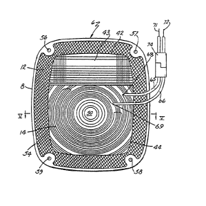
As best seen in Figs. 3 and 4, cover 6, which
illustratively is a lens, comprises a thermally conductive,
translucent cover plate 8 constructed from an integrally
molded plaskic. Although in the pre~erred embodiment cover
6 assumes a rectangular shape, cover 6 could just as easily
be circular in shape, or any other suitable shape. Cover
plate 8 includes an aperture 42 receiving a back-up light
cover 43, and has exterior surface 10 and interior surface
6--
1 12. A central section 17 compxising back-up ligh~ cover ~3
received in aperture 42, and a raisec! portion 18 providing a
running light/brake light lens. Surroundiny central section
17 is a smooth marginal portion l9. ~n the present
embodiment, indicator light 2 is covered by a lens 6;
howevsr, in okher embodiments various types of covers would
be suitable for employment as cover ~. For example, cover 6
could just as easily be a flat sheet of plastic or any other
suitable cover that would fit over aperture 22 for mounting
on strip 26. Additionally, in an alternative embodiment
cover 6 could be incorporated into a sealed beam unit.
A light focusing section 44 including a concentric
pattern of grooves 46 is molded on the interior surface 12
of cover plate 8 for purposes of focusing light rays from
bulb 35. Each groove 46 is defined by two, circular,
sloping ridges 48 (Fig~ 5) and grooves 46 extend radially
outward from the center 50 until terminating into a
reflective portion 52. Reflective portion 52, which is
comprised of longitudinally extending, pyramidally-shaped
projections (Fig. 5) on interior surface 12, surrounds
section 44 and aperture 42 for purposes of reflecting any
rays directed toward cover 6 in the dark. Increased
reflectivity enhances the safety of vehicle 4 by making it
more visible to approaching traffic at night, even when
parked along the side of a road with its lights turned off.
Encircling the interior surface 12 of cover plate 8 is
raised rim portion 54 in which four apertures 56-59 are
located--one in each corner.
Elongate resistor 14 is operatively connected in a
widespread pattern to cover plate 8 to heat at least a major
portion of the exterior surface lO of cover plate 8. The
-7-
~ ~73;~
l illustrated resistor 14 comprises a flexible wire that is
bent in such a way as ~o con~orm wi~h some of the grooves
46, as best demonstra~ed in Figs. 3 and 5. Resistor 14 may
be positioned or mounted in selected yrooves 46 with an
adhesive bond (Fig. 5), or inserted between the e~terior
surface lO and interior surface 12 of cover plate 8 during
the molding of the lens plate.
Electrical connector 63 (Fig. 3), in the present
embodiment, comprises wires 65 and 66 coupled with wires 71
and 72 via connector 740 Resistor 14 includes terminal ends
68 and 69 for purposes of electrically connecting resistor
14 using connector 63 to electrical system 16 to induce an
electrical current through cover 6. Illustrated wires 65
and 66 are soldered to resistor ends or terminals 68 and 69,
respectively, and coupled with wires 71 and 72 by way of a
splicing connector 74, to facilitate easy release of lens 6
from indicator light 2. In an alternative embodiment wires
65 and 66 can be spliced directly into bulb 35.
Consequently, a connection between electrical system 16 and
~0 resistor 14 is co~pleted upon inserting bulb 35 into socket
34.
In the preferred embodiment, the translucent cover
plate 8 is composed of an acrylic polymer such as polymethyl
methacrylate. Consequently, plate 8 is rigid so that it can
both be heated, and withstand adverse weather conditions,
without changing shape or losing its desired protective
form. The total length of copper wires 65, 66 coupled with
copper wires 71 and 72 by way of the rubber coated splicing
connector 74 is at least lO inches. Such length is great
enough to allow convenient attachment of resistor 14 to
socket 34. Resistor 14, which is composed of a highly
-8-
~3~
1 resistive metal, such as bare nickel or chromium, or
resistive paint or tape, has a resistance of approximately 6
ohms and draws a current of approximately 2 amps.
In one embodiment, resistor 14 is a~fixed to light
focusing section 44 as illustrated in Fig. 3. The resistor
14 follows a looping path from terminal end 68 to terminal
end 69. Beginning at end 69, resistor 14 completes a path
consisting of the bet~er part of one circle around center 50
and shifts by ninety degrees to the right crossing three
L0 grooves. After completing an arc of about 300 degrees in a
counter-clockwise direction, resistor 14 shifts by ninety
degrees to the right crossing two grooves. The outermost
arc of about 320 degrees terminates at end 68. In total,
three partial loops, covering the majority of light focusing
section 44 are formed. When resistive wire is used to form
the loops, the gauge of the wire will preferably vary
according to the area of focusing section 44. In other
words, for larger areas the gauge is preferably increased
and vice versa. The resistor 14 is illustratively arranged
in the above-mentioned path, coated with epoxy cement, and
allowed to set for a suitable period of time. By affixing
the resistor 14 to light focusing section 44 in three evenly
spaced partial loops, heat i6 dissipated over the entire
portion o~ section 44, constituting 41% of the area of cover
6. Since the area of light focusing section 44 is 18 square
inches, and the conventional electrical system 16, which in
the illustrated embodiment, operates at 12 volts, the power
dissipated across section 44 is 1.3 watts/in2. Residual
heat is transferred from light focusing section 44 to brake
light cover 42 and reflective portion 52 causing any frozen
particulate to be melted from the exterior surface 10 of
_9_
~7~
1 cover plate 8.
METHOD OF ASSEMBLY
Explanation of the assembly of indicator light 2
is made by reference to Figs. 1, 2 an~ 6. Wires 71 and 72
are operatively conneated in parallel with bulb socket 34 as
illustrated in Figs. 2 and 6, so that when switch 38 is in
the "on" position, current is induced in resis~or 14. Cover
6 is secured to mounting strip 26 (Figs. 1 and 2) by
aligning apertures 28-31 with apertures 56-59, respectively,
and fastening cover ~ by using round head machine screws
76-79, or other similar fasteners.
Due to the construction of indicator light 2,
cover 6 is easily fastened onto indicator light 2 for use
during wintry periods as a replacement for a conventional
lens, and disassembled and stored otherwise. Thus,
indicator light 2 is adaptable for quick installation, for
use during the winter, on any suitable vehicle in order to
melt frozen particulate on the exterior surface thereof for
improved visibility of said indicator light and related
vehicle safety. Making indicator lights visible during
periods of wintry conditions is not only advantageous
because it allows those following the vehicle to be more
aware of that vehicle's intentions with respect to braking,
turning, etc., but also because it enhances emergency winter
services. For instance, a snowplow employing the present
indicator light is more visible to other vehicles, thus
affording them the opportunity to take any necessary safety
precautions.
In the foregoing description, it will be readily
appreciated by those skilled in the art that modifications
may be made to the invention without departing from the
--10--
~73~
1 concepts disclosed herein. Such modi~ications are to be
considered as included in the following claims unless these
claims by their language expressly state otherwise.
;,, ' ~ ,
~7~
- SIIPPLEME~TARY DISCLOSURE
Alterna e Embo~
Referring to Figs. ~ and 9, another pre~erred
embodiment o~ indicator light 2 i~ illustrated. A~ wlll be
recognized, indicator light 2a i8 con~txucted and operakes
in a fa~hion similar to previously dascribQd indicator liyht
2. There~ore, corrQsponding element~ o~ indicator light 2a
are given rs~Qrence numeral~ correspondlny to thQ re~erence
numerals o~ indicatox light 2, with tha addition o~ a 8U~iX
"a".
The most signi~icant di~erencelbetw~en indicator
light 2 and ~ndicator light 2a resides inlkhe saparation o~
cover pl~te ~a and elongate re~istor 14a~ More
speci~ically, alongate resistor 14a i~ operatively connected
in a widespread spiral pattern ~o a support 100, havlng
upper and lower attachment ~langes 102 and 103. TheMe
~lange~ are secured to the reflector 24a to support th~
resistor proximate the lens lOa.
Elongate resistor 14a i~ aonstruoted ~rom the ~ame
material as elongate resistor 14, possessing a resistance
comparable to that o~ elongate resistor 14, Elongate
resistor 14a i~ connected to ~upport 100 by ~onventional
means such as silver soldering or the like. Elongate
resistor 14a includes terminal ends 68a and 69a ~or
connection to leads ~ and 66a, respectivQiy.
Elongate resi~tor 14a i~ po~itioned behind plate
8a æo that heat i~ directad toward cover plat2 interlor
sur~ace 12a when current i8 conducted thxough alongate
re8i5tor 14a. Although the resistor i~ shown slightly
spaced from the plate 8a, the resistor could abut the platQ
to produce the desired re~ult. Tha resistanca and length o~
the resistor is s~lected so as to provide adequate heat to
melt ~rozen particulate on the plate 8a.