Note: Descriptions are shown in the official language in which they were submitted.
~ 3~
,The present invention relates to devices
having replaceable membranes which cooperate with an
electrode assembly to determine the amount of a
substance in a biological fluid.
Backqround of the Invention
. _
The continuous measueement of substances in
biological fluids is of interest in the study and
control of metabolic disorders. Electrode systems
have been developed for thiE purpose whereby an
enzyme-catalyzed reaction is monitored by an
electrochemical sensor. In such electrode systems,
the electrochemical sen's~r'comprises an electrode
with potentiometric or amperometric function in close
contact with a thin layer containing an en~yme in
dissolved or insoluble form. The thin layer may also
include a co-enzyme.
In c~onventional practi~e, a semipermeable
membrane separates the thin layer of the electrode
containing the enzyme from ~he sample of biological
fluid that includes the sub6tance to be measured.
The electro h~mical sensor measures the concentration
of the substance involved in ~he en2yme reaction.
For exampIe, the concentration of a co-enzyme or a
reaction product can be determined. This
concentration may be related to the substrate
concentration in the sample by its stoichiometric '
relationship and by calibration of the electrode
system.
~, .. .
~L~73~3~3'3
A number of enzyme elec~rodes have been
developed, and ~he operation o~ those electrodes
varies depending on the nature of the enzyme reaction
and the particular substance being measured. For
example, enzyme electrodes include those that
measure (1) a reactant or product of the enzyme
reaction; (2) the consumption of a co-enzyme based on
the decrease of its initial concentration and (3) the
amount of the reduced or oxidized form of a co~enzyme
produced during the enzyme reaction.
The operation o~ a particular enzyme
electrode depends on a nu~ber of parameters including
dif~usion processes, kinetics of the enzyme reaction
and the type of electrochemical sensor. In
particular, the operation of the electrode can be
affected by the diffusion of substances through the
semipermeable membrane.
Electrode systems that include enzymes nave
been used to convert amperometrically inactive
substances into reaction productæ which are
amperometrically active. Specifically, in the
analysis of blood for glucose content, glucose (which
is relatively inactive amperometrically) may be
catalytically converted by the enzyme glucose oxidase
in the presence of oxygen and water to gluconic acid
and hydrogen peroxide. ~ydrogen peroxide is
anodically ac~ive and produces a curren~ which is
proportional to the concentration of hydrogen
peroxide in the blood sample and thus to the
concentration of glucose in the sample.
In a sample of undiluted whole blood,
however, a molar excess of plasma glucose is present
relative to the amount of plasma oxygen. As a
result~ if a semipermeable membrane is not included
over the enzyme, the concentration of glucose in the
3~$~
--3--
sample relative to ~he concen~ration o~ oxygen will
be so high that the glucose oxidase-catalyzed
reaction of glucose and oxygen to gluconic acid and
hydrogen peroxide will be oxygen limited.
The effec~ of an oxygen limited reaction is
~hat the range of glucose concentrations that can be
measured with such an electrode is very limited. In
particular, linearity is not achieved above minimal
concentrations of glucose. In a clinical setting~
linear glucose levels must be obtained at glucose
concentrations of at least up to about 500 milligrams
per deciliter (mg/dl). Without a semipermeable
membrane over the enzyme, linear glucose levels can
be obtained only up to about 40 mg/dl. Thus, the
lS purpose of he membrane over the enzyme in a glucose
sensing electrode system is to limit the amount of
glucose that passes or diffuses through the
membrane. This extends the upper limit of linearity
of glucose measurement from a low value without the
membrane to ~ high value with the membrane.
The two fundamental diffusion processes by
which a semipermeable membrane can limit the amount
of a substance that passes therethrough are diffusion
through the semipermeable membrane as a monolithic,
homogeneous Structure and diffusion through the
semipermeable membrane as a porous structure. The
processes of diffusion of substances through these
different types of membranes differ considerably.
A semipermeable membrane can comprise a
porous structure consisting of a relatively
impermeable matrix that includes a plurality of
~microholes" or pores of molecular dimensions.
Transfer through these membranes is primarily due to
passage of substances through the pores. In other
~7~
, ~
--4--
words, the membrane ac'cs as a microporous barrier or
sieve.
Examples of materials that may be used to
form such membranes include polyethylene, polyvinyl
chloride~ tetrafluoroethylene, polypropylene,
cellophane, polyacrylamide, c~llulose acetate,
polymethyl methacrylate, silicone polymers,
polycarbonate, cuprophane and collagen.
Selectivity in such a membrane can be
explained on the basis of the molecular size of the
diffusing substances. For substances much smaller
than the diameter of the pores, passage of the
substance through the membrane is relatively
unimpeded~ As the effective molecular diameter of
the substance approaches the diameter of the pore,
the pore will exert a drag on the diffusing
substance, reducing its permeability to a value lower
than that expected on the basis of the membrane
porosityO If the molecules of the substance are too
large, they will not pass through the membrane at all.
Since transfer is due primarily to passage
- of the substance through pores t the permeability is
directly related to the size o the pores and to the
molecu}ar volume of th~ diffusing substance. As a
result, there is little selectivity in the separation
of two chemically or structurally related molecules,
excep~ when their molecular size is approxima~ely the
same as the size of the pore, When this occurs,
there is the possibility that forces acting between
the substance and the surface of the pore channel may
influence the rate of transfer.
Also, the upper size limit to diffusion will
be determined by the largest pore diameter, and the
overall diffusion rate will depend on the total
number of pores for movement of the substance.
-5
Passage of a substance through a monolithic,
homogeneous membrane, on the other hand, depends upon
dissolution and diffusion of the substance as a
solu~e through a solid~ non-porous film. As used
herein, the term "monolithic" means substantially
non-porous and having a generally unbroken surface.
The term ~homogeneous" t with reference to a membrane,
means having substantially uniform characteristics
from one side of the membrane to the other. However,
a membrane may have heterogeneous structural domains,
for example, created by using block copolymers, and
still be characterized functionally as homogeneous
with respect to its dependence upon dissolution
rather than sieving to effect separation of
substancesc A monolithic membrane can ~hus be used
to separate components of a solution on the basis of
properties other than the size, shape and density of
the diffusing substances. The membrane acts as a
barrier because of the preferentlal diffusion
therethrough of some substance (a solute).
Despite advances in membrane technology,
- devices that include semipermeable membranes which
have been used to de~ect and measure the presence of
a substance in a biological 1uid have generally been
restricted to laboratory environments. This is
because the devices are generally large and complex
and require extensive training to operate. In
addition, these devices have been som~what limited
because of the difficulty in replacing a membrane
used with the electrode.
A need exists for an improved device that
selectively measures the presence and the amounts of
particular substances in biological fluid~. Such a
device should accurately measure the amount of a
substance in a sample without dilution or
7~;3~
pretreatment of ~he sample. In addition, a basis for
selecting appropriate membrane materials for use in
such devices is needed. The device should also be
easy to use and provide a means for replacing the
membrane as necessaryO
Summary of_the Invention
The present invention relates to a
biological fluid measuring device which permits rapid
and accurate determination and measurement of the
amount of a particular substance in a biological
fluid such as bloodO
Generally, the device includes a main
bousing carrying electronic circui~ ~eans and at
least one electrode. In a preferred embodiment, at
least two electrodes are carried by the houslng.
cartridge is removably mounted on the housing. The
cartridge includes a membrane which is operably
associated with the electrodes when the cartridge is
mounted on the housing. It is, of course r possible
to design a device wherein one elect~ode is carried
by the housing and a second electrode is carried by
another component of the device, as by the
cartridge. Yor ease of description, however, the
present device will be described as including at
least two electrodes carried by the housing. The
cartridge also includes means for protecting the
membrane from the ambient surroundings when the
device is not in use.
I~ a preferred embodiment, the housing
includes a case having an upper portion and a lower
portion which togethez define a cavity. The
electronic circuit is received within the cavity.
The electrode is carried by a post which extends
upwardly from a base surface defined by the upper
portion of the case.
~3~3
--7--
The cartridge preferably includes a body
portion which is releasahly,mounted on the upp~r
portion of the case and a cover which is mavably
mounted as by a hinge on the body portion. The body
portion preferably defines a sidewall which together
with the membrane defines a well. The well receives
the biological fluid such as a droplet of blood.
Because of the particular design of the present
invention, the well can be particularly small thereby 10 minimizing the amount of biological fluid sample
needed for analysis. In the case of blood, this
minimizes both the emotional and physical trauma to
the patient.
The body portion preferably includes a
collar which extends about the pos~ such that, when
the cartridge is .nounted on the case, the membrane is
placed in contact with the electrodes and is
stretched over the surface of the electrodes. This
insures good operative contact between the electrodes
and the membrane.
The electrodes, the supporting structure for
the electrodes such as the post, and the membrane
together form an electrode assembly. The membrane is
a multilayered structure including layers formed of
materials such as polyethylene, polyvinyl chloride,
tetrafluoroethylene, polypropylene, cellophane,
polyacrylamide, cellulose acetate, polymethyl
methacrylate, silicone polymers, polycarbonate,
cuprophane, collagen, polyurethanes and block
copolymers thereof. The membrane prevents direct
contact of the fluid sample with the electrodes, but
permits selected substances of the fluid to pass
through the membrane for electrochemical reaction
with the electrodes.
In a parti~ularly preferred embodiment, the
membrane is a semi-permeable multilayered membrane
naving at least one layer ormed of a nonporous block
copolymer having hydrophobic segments and hydrophilic
segments ~hat limits the amount of a substance
passing therethrough and a second layer including an
enzyme that reacts with the substance to form a
product.
In a more preferred embodiment, the
electrode assembly comprises an electrode, a first
~outer) layer of a block copolymer that limits the
amount of a hydrophilic substance passing
therethrough, a second (intermediate) layér of a
block copolymer including an enzyme bound to the
first layer and a third tinner) layer of a block
copolymer bound to the second layer and covering the
surface of the electrode. The third layer is
permeable to relatively low molecular weight
substances, such as hydrogen peroxide 7 but restricts
the passage of higher molecular weight substances.
The preferred polymers which form the above
described membrane layer~ are selected based on
permeability and water swelling. A~ accept~d
industry test procedure for determining the
permeability of a coating or membrane is ASTM E 96
which measures the moisture-vapor transmission rate
of a material. (American Society for Testing and
Materials, Philadelphia, PA).
As used herein, the moisture-vapor
transmission rate (MVTR) of a membrane material is
expressed in grams per square meter per 24 hours and
is one means of defining the water resistance of a
material.
,
~ ~ 7.$~
The MVTR of a material may be expressed by
the equation:
Q
MVTR =
s
wherein the letter ~Q" represents the amount of water
vapor (in grams) that permeates the film; the letter
~a" represents the film area (in square centimeters)
and the letter ~t~ represents the time (in hours at a
designated thickness). This value can be converted
to grams of water per square meter per 24 hours. The
MVTR values identified herein are for membranes that
are about 1 mil thick.
The MVTR of the first (outer) layer
described herein should be greater than about 4000
grams per square meter per 24 hours, preferably
grea~er than abou~ 5000 grams per square meter per 24
hours.
The MVTR of the third ~inner) layer of the
assembly should be from about 500 to about 4000 grams
per square meter per 24 hours~ preferably from 1000
to 3500 grams per square meter per 24 hours.
It will, of course, be understood that the
above MVTR values for each layer can be varied or
optimized depending on the substance to be measured
and the enzyme that i~ employed.
In a preferred embodiment, the enzyme is
glu¢ose oxidase and the substance to be measured is
glucose. The amount of ~lucose, for example, in an
aliquot of undiluted whole blood, is determined by
measuring the amount of hydrogen peroxide produced
during the oxidation of glucose to gluconic acid by
the enzyme.
Preferred polymers may also be selected by
studying water uptake or the swelling of the
.. ,:
73~
--10--
polymer. This is normally measured by soaking the
polymer sample in water at a controlled temperature
and exposure conditions until equilibrium is achieved
followed by rapid drying of surface water and
weighing of the polymer sample. Subtracting the dry
weight from the swelled weight and then dividing by
the dry weigh~ and multiplying the value obtained by
100 provides the swell rate as a percent of dry
wei~ht. The swell rate of the first (outer) layer
described herein should be greater ~han about 5
percent and preferably greater than about 10
percent. The swell rate of ~he third linner) layer
should be less than about 5 percent preferably less
than about 3 percent.
The present invention, howev~r, is not
limited to the measurement of glucose concentrations,
and other enzyme-substrate systems can be used.
Examples of other enzymes include galactose oxidase,
uricase, cholesterol oxidase, alcohol oxidase,
lactose oxidase, L-amino acid oxidase~ D-amino acid
oxidase, xanthine oxidase and ascorbic acid oxidase.
Nonetheless, to demonstrate the improvement
of this invention over other membrane systems, the
invention will be described in terms of measuring
glucose concentrations based on the production of
hydrogen peroxide by the action of glucose oxidase.
The membrane systems currently available are
based on semipermeable membranes with microholes or
pores. With these membranes there is little
selectivity in the separation of substances that are
rather close in size, except when the molecular
diameters of the substances approach the diameters of
the pores. When this occurs, forces between the
substance and the surface of the pore channel may
influence the rate of transfer~
" ' , '. ~,. '`;' .. ,:. .
73~"3
--11--
The layers of the preferred multilayered
membrane described herein each comprise homogeneousv
monolithic membranes and differ in composi~ion,
structure and operation from conventional microporous
membranes~ This represents a substantial improvement
over current membrane systems in terms of ease of
manufacturingi lifetime of enzyme activity, and the
ability to measure the concentrations of substances
in undiluted samples.
In summaryp passage of substances through
the membranes described herein depends upon
dissolution and diffusion of the substance through a
solid, non-porous film. Components of a solution can
be separated on the basis of properties other than
the size, shape and density of the diffusing
substanceO
Brief Description of the Drawin~s
Figure 1 is a perspective view of biological
fluid measuring device of the present invention
showing a cartridge received on a housing;
Figure 2 is an explode~ perspective view of
the device of Figure 1 showing the cartridge above
and separated from the housing;
Figure 3 is a top plan view of the device o
Figure 1 showing the cover of ~he cartridge open and
the membrane exposed;
Figure 4 is a side elevational view taken in
section along the plane 4-4 of Figure l;
Figure 4a is an enlarged view of the portion
of Figure 4 that is outlined in phantom;
Figure 5 is a top plan view of a second
embodiment of the electrode assembly;
Figure 6 is a side elevational view showing
a device including the electrode assembly of Figure 5
~ ~7~33~
taken in section along a plane similar to that shown
as plane 4-4 of Figure l; and
Figure 7 is an electronic circuit diagram in
block form~
5 De~ L~L3~s~ t~n of the Invention
The present invention relates to a
biological fluid measuring device which permits rapid
and accurate measurement of the amount of a
particular substance in 2 biological fluid. One
particular use of the present invention is to
determine the level of glucose in blood using only a
small sample. This is a particularly important
measurement for individuals having diabetes, and the
device is a substantial development over devices that
are now being used by individuals with diabetes to
det2rmine glucose levels.
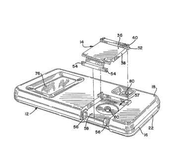
Referring to Figures 1 and 2, the measuring
device comprises a main housing 12 and a cartridge 14
which is removably mounted on the housing (see Figure
2). This permits the cartridge 14, which can be made
disposable,to be easily replaced as needed~ The
- construction of the cartridge will be described in
det~il with reference to Figures 4 and 4a. The
housing 12 includes a case 16 having an upper portion
18 and a lower portion 22. The upper portion 13 and
lower portion 22 are connected together by any
particular fastening means such as several screws
which are not shown.
Referring also to Figures 3 and 4, the main
housing 12 also includes electronic circuit means
which can be carried in part on a circuit board 24.
The electronic circuit means is preferably maintained
in a cavity 26 which is defined by the case 16. The
housing also includes at least one electrode. In the
13 -
embodiment shown in Figure 4, three electrodes 28, 30
and 32 are shown.
The operation of these electrodes is
discussed in more detail below. The cartxidge 14
includes a membrane 34 which is operably associated
with the electrodes 28, 30 and 32 when the cartridge is
removably mounted on the housing 12. The cartridge 14
also includes means for protecting the membrane when
not in use. The protection means is preferably a cover
36 which is movably mounted on a body portion 38 of the
cartridge 14. Alternatively, the cover 36 may be
mounted on the case 16. In the illustrated embodiment,
the cover 36 is movably mounted on the body portion 38
by a hinge assembly 40.
Generally, the cover 36 has a first position
such as shown in Figures 1 and 4 in which it protects
the membrane 34 and a second position such as shown in
Figure 3 which permits access to the membrane. Access
to the membrane 34 is necessary to place the biological
fluid sample on the membrane for analysis.
As is more clearly shown in Figure 4a (which
is an enlarged view of a portion of Figure 4), the body
portion preferably defines an opening having a sidewall
42 which together with a portion of the membrane 34
defines a well 44 having a bottom 45. The bottom 45 of
the well is defined at least in part by the membrane
34. The biological fluid sample is placed in the well
44 for analysis.
Generally, the sidewall 42 defines an opening
of less than 4 millimeters in diameter and the well 44
has the depth of less than 2 millimeters. As a result,
the well has a volume of less than about 0.1 to 0.2
cubic centimeters. This substantially minimizes the
size of the biological fluid sample necessary for
analysis down to the
73~ 3
-14-
sample sizes a small as abou~ five microliters.
Because the size of the sample can be particularly
small7 compensation for temperature changes during
analysis which was often necessary with previous
devices can be avoided.
The protection means of the cartridge l~
preferably also includes means for sealing the well
44 and hence the operative portion of the membrane 34
at the bottom 45 of the well 44 from the ambient
surroundings. This can include a flexible gasket 4S
which extends about the well 44 and cooperates with
the body portion 38 and cover 36. The gasket 46 is
preferably mounted in a groove 48 defined by the body
portion 38 and is engaged by a ring S0 carried on the
cover 36.
When the cover is in its second or closed
position such as shown in Figure 4~ the ring 50
engages the gasket 46 to seal the well 44 and
membrane 34 from the ambient surroundings and to
prevent dehydration of the membrane. This also
prevents damage to the membrane by physical intrusion
or dirt. The ring 50 is preferably provided with a
edged surface which bites into the gasket to provide
a particularly effective sealO
A retaining means is also provided for
releasably retaining ~he cartridge 14 and its body
portion 38 on the housing 12. The retaining means
preferably includes a detent 52 on the cartridge 14
which is received in a recess 53 defined by the upper
portion 18 of the case 16. The retaining means also
preferably includes at least one, and optimally, two
wings 54 on the body portion 38 of the cartridge 14
which are received in one or more slots 56 on the
case 16. (See, in particular, Figure 2). The slots
56 are generally perpendicular to the cover 36 so
-15-
that openiny the cover will not disengage the wings
54 from the slots 56.
The upper portion 18 of the case 16
preferably defines a recessed cell 57 (see Figure 2)
into which the cartridge 14 is received. The bottom
portion of the cell 57 is defined by a base surface
58. The electrodes 28, 30 and 32 preferably extend
upwardly from the base surface 58. The ~lectrodes
are preferably mounted within ~ post 60 which
supports the electrodes as they extend upwardly of
the base surface 58. The post is preferably
generally annular in design with ~he interior portion
thereof ~illed with an electrically nonconductive
support material 62 such as a hardened
polyepoxide-containing resin. The electrically
nonconductive support material 62 and the top
portions of the electrodes define a membrane contact
surface 64. The membrane contact surface 64 is
preferably generally dome-~haped such that the
membrane 34 can be stretched over the contact surface
to more effectively place the membrane in operative
association with the electrodes.
The body portion 38 preferably also includes
a collar 66 which extends opposite of the well 44
with respect to the membrane 34 where it defines the
bottom 45 of ~he well. As shown in Figure 4, the
collar 66 extends about the post 60. The membrane 34
is preferably attached to a retaining surface 65 by
an adhesive at the edge of the collar 66 with the
30 portion of the membrane within the collar being free
to move. As the cartridge 14 is mounted on the
housing 12, the membrane is hen stretched over the
post 60 providing continuous contact between membrane
34 and the contact surface 64.
~73~3~ 3
--16--
The cover 36 is preferably provided with a
closure means 72 such as one or more latche~ which
engage the body por~ion 38. ~enerally, the force
necessary to disengage the closure means 72 from the
body portion 38 should be less than that necessary to
disengage the wings 54 from the slots 56. In this
manner, the operator can easily open the cover 36
without accidentally disengaging th~ cartridge 14
from the main housing 12.
The electrodes 28, 30 and 32 together with
support assembly such as post 60 and the membrane 34
comprise the electrode assembly. It is this assembly
which is contacted with the body fluid sample for
analysis. The electrode assembly 74 is operably
associated with the electronic circuit means which
analyzes the current from the reaction of the
components in the body fluid with the electrodes.
The electronic circuit means i in turn operably
associated with display means such as a liquid
crysta~ display 76 to indicate amount of glucose in
the fluid sample.
Referring to Figure 5, another embodiment of
the el~ctrode assembly 74 is shown wherein the three
electrodes 28, 30 and 32 are deposited onto a ceramic
surface 66. An electrically nonconductive material
62 is applied as a coating over ~he electrodes to
form an insulating barrier. ~ portion of each
electrode, however, is not coated to form a membrane
contact surface 64 so that a membrane can be applied
over the electrodes in operative contact therewith.
Figure 6 shows the electrode assembly 74 of
Figure 5 in the device~ In particular, the electrode
assembly including the membrane 34 is positioned
within a recess 78 in the base surface 58 of the
recessed cell 57. The cartridge 14 is then
~ 7~
-17-
positioned within the recessed cell as described
above whereby ~he bottom 45 of the well 44 in the
body portion 38 of the cartridge contacts ~he
membrane 34. A cover 36 (as shown in Figure 4) can
be attached to the body portion 38 to protect the
membrane when the device is not in use.
The three electrode configuration in
combination with the chemi~al reactions occurring in
the multilayered membrane and on the electrode make
possible consistent electrode behavior and, in
particular, performance of the reference electrode
that is stable with time. I~ is well known in the
art that silver/silver chloride electrodes provide a
stable reference system for electrochemical sensors.
A silver/silver chloride electrode is
typically formed by treating a silver surface with an
oxidant and chloride ions (such as by treatment with
ferric chloride or a neutral hypochlorite solution),
by electrochemical plating of chloride ions onto a
silver surface or by the mechanical forming of silver
and silver chloride by sintering or similar processes.
When this type of electrode is used in a two
electrode configuration with the reference cathodic,
chloride ions will be lost from the reference
electrode which eventually leads to unstable
electrode behavior. According to the present
invention, permanent stable reference electrode
behavior is achieved when the hydrogen peroxide
produced in the membrane oxidizes the silver metal to
silver oxide which is then converted to silver
chloride by chloride ion. Advantages include ease of
manufacturing of the electrode, self-forming and
self-maintaining electrode behavior and long-term
reference electrode stability.
-18-
The rela~ively low power needs of t'ne
present electrode system, as compared to the
relatively high powe~ needs of conventional light
reflectance-based methodst permit use of a very
compact, lightweight device having an extended
battery life. CMOS circui~ry is used throughout the
device and provides a use-dependent battery life of
one to two years.
A representative electronic circuit for the
device is shown in Figure 7, but other circuits may
also be employed. See, for example, Implantable
Sensors for Closed Loop Prosthetic Systems, edited by
Wen H. Ko, ch. 12, pages 167-175, Futura Publishing
CoO, Mount Kisco, N~Yo (1985)~
During operation of the device, glucose from
the blood sample produces a current flow at the
working electrode 28. Equal current is provided by a
counter electrode 30 in a reference circuit 82. The
current is converted in an analog section 84 by a
current to voltage converter to a voitage which is
inverted, level-shifted and delivered to an
Analog/Digital (A/D) converter 86 in the
microprocessor 88. As part of the calibration
circuit means, the microprocessor can set the analog
gain via its control pork 90. The A/D converter is
activated at one second intervals. The
microprocessor looks at the converter output with any
number of pattern recognition algorithms known to
those skilled in the art until a glucose peak is
identified. A timer is then activated for about 30
seconds at the end of which time the difference
between the first and last electrode current values
is calculated. This difference is then divided by
the value stored in the memory during instrument
3{~
~19-
calibration and i5 then multiplied by the calibration
glucose concentration~ The glucose value in
milligram percent or millimoles per liter is then
displayed on the LCD display screen 94.
During this operation sequence, prompts or
messages may be displayed on the LCD screen to guide
the user through the calibration and sample
measurement procedures. In addition, prompts may be
displayed to inform the user about necessary
maintenance procedures, such as "Replace Sensor" or
"Replace Bat~ery.W ~n on/off button B0 initiates the
operation and calibration sequences~
As indicated above, the membrane is a
multilayered structure including layers formed of
materials such as polyethylene, polyvinyl chloride,
tetrafluoroethylene, polypropylene, cellophane,
polyacrylamide, cellulose acetate, polymethyl
methacrylate, silicone polymers, polycarbonate~
cuprophane, collagen, polyurethanes and block
copolymers thereof.
In a particularly preferred embodiment, the
m~mbrane is a semi-permeable multilayerd membran2
having at least one layer formed o~ a nonporous block
copolymer having hydrophobic segments (such as
~ilicone polymer segments, aromatic and aliphatic
polymer segments, polypropylene oxide segments,
polytetra-methylene oxide segments and the like) and
hydrophilic segments (such as polyoxyethylene
segments, polyvinylpyrrolidone segments, polyvinyl
alcohol segments and the like) that limits the amount
of a substance passing therethrough and a second
layer including an enzyme that reacts with the
substance to form a product.
The first layer limits the amount of a
substance in a fluid that can pass therethrough. The
substance can react with the enzyme in the second
~ ~7~3,t:~
-20~
layer to produce one or more reaction products. A
third layer that i5 permeable to one of the reaction
p~oducts, but which restricts the passage of other
materials may also be used.
The ability of each layer to limit the
amount of a molecule that can pass therethrough may
be expressed in terms of the moisture-vapor
transmission rate ~MVTR) and water swelling of the
material that forms the layer. As used herein, the
MVTR of a material is measured as descrihed in ASTM E
96~
The MVTR of the block copolymer of the first
layer should be greater than about 4000 grams per
square meter per 24 hour~, preferably greater than
about 5000 grams per square meter per 24 hours. The
water swelling of this layer should he greater than
about 5 percent.
The MVTR o the block copolymer of the third
layer should be from about 500 to about 4000 grams
per square meter per 24 hours. The above-values
relate specifically to layers that are employed to
measure the amount of glucose in a biological
sample. It will be understood that block copolymers
having different MVTR values can be used to measuré
the amounts of other substances in biological sample
and the description of glucose measurement is only
illustrative.
The most preferred membranes of this
invention are formed of polyurethanes which, of
course, include urethane groups and polyurethaneureas
which also include urea groups. The polyurethanes
and the polyurethaneureas of the present membrane
system are based on poly(oxyalkylene) glycols
including poly(oxyethylene) glycol~ In accordance
3~
-21-
with conventional usage, both types of polymers will
be referred to herein as polyurethanes.
Membranes of polyurethanes based on
poly(oxyalkylene) glycol display no predic~able
relationship between molecular weight and
permeability. The unique separation observed with
the present membranes may be explained on the basis
of substance membrane or solute-membrane interactions
which tend to affect the partitioning of the
substance into the membrane This partitioning is
not due only to the hydrophilic polyloxyalkylene)
glycol or "soft" segment, but the hydrophobic or
~hard" segment of the block copolymer also
contributes to the overall selectivity.
Thus, by changing the structure of the
hydrophobic segment of the block copolymer and/or
increasing or decreasing the molecular weight of the
poly(oxyalkylene) glycol, the selectivity of the
membrane system can be modified. In the membrane
system of this invention, for example, the use of two
dif~erent membranes of block copolyether urethanes
based on poly(oxyalkylene) glycol produces the
desired selectivity for glucose and hydrogen peroxide.
The preferred poly(oxyalkylene) glycols of
this invention include poly~oxyethylene) glycols~
poly(oxyte ramethylene) glycols and
poly(oxypropylene) glycols.
The organic diisocyanates suitable for use
in the preparation of the polyurethanes of the
present membranes include 2,4-toluene diisocyanate,
2,6-toluene diisocyanate and 4,4'-diphenylmethane
diisocyanate. The use of 4~4'-diphenylmethane
diisocyanate is preferred.
Diols useful herein include ethylene glycol,
propylene glycol, 1,5-dihydroxypentane,
~ 7~
-22-
1~6-dihydroxyhexane, 1,10-dihydroxydecane,
1,4-cyclohexane diol, 1~3-dihydroxyneopen~ane and
alpha, alpha'-dihydroxy-p-xylene.
Diamin~s useful in the preparation of the
polyurethanes described herein include ethylene-
diamine, 1,2- (and 1,3-) propanediamine, and
methylene-bis-o chloroaniline.
Exam~e 1
The polyurethanes are preferably prepared as
block copolymers by solution polymerization
techniques as generally described in Lyman, D~Jo ~ J~
Polymer_Sci. ~ _7 49 (1960). Specifically, a
two-step solution polymerization technique is used in
which the poly(oxyethylene) glycol is first "capped"
by reaction with a diisocyanate to form a
macrodiisocyanate. Then the macrodiisocyanate is
coupled with a diol (or diamine) and the diisocy~nate
to form a block copolyetherurethane (vr a block
copolyurethaneurea)~ The resulting block copolymers
are tough and elastic and may be solution-cast in
N,N-dimethylformamide to yield clear films that
demonstrate good wet strength when swollen in water.
In particular, a mixture of 8~4 grams (0.006
mole) poly(oxyethylene) glycol (CARBOWAX 1540, Union
Carbide Corp., New York, NY) and 3.0 grams (0.012
mole~ 4,4'-diphenylmethane diisocyanate in 20
milliliters (ml) dimethyl sulfoxide/4-methyl-2-
pentanone (50/50) is placed in a three-necked flask
equipped with a stirrer and condenser and protected
from moisture. The reaction mixture is stirred and
heated at 110 degrees C for about one hour. To this
clear solution is added 1.5 grams (0.014 mole)
1,5-pentanediol and 2.0 grams (0.008 mole)
4,4'-diphenylmethane diisocyanate.
'73 3
-23-
After heating at 110C for an additional two
hours, the resulting viscous solu~ion is poured into
water. The ~ough~ rubbery, white polymer precipitate
that forms is chopped in a Waring Blender, washed
with wa~er and dried in a vacuum oven at about 60
degrees C. The yield is essentially quan~itative.
The inherent viscosity of the copolymer in
N,N-dimethyl formamide is 0.59 at 30 degrees C (at a
concentration of about 0.05 percent by weight~.
Example 2
A membrane formed of a homogeneous,
nonporous block copolymer may be prepared as
follows. Polymerization is carried out in a 2-liter
glass flask with a detachable top containing five
inlets. The inlets provide for nitrogen passage,
condenser attachment, stirring, thermometer placing,
and ingredient addition. A regulated flow of
oxygen-free nitrogen passes from a cylinder, through
the apparatus, into a water trap, and to the drainO
The contents of the reaction flask are stirr~d by a
Teflon blade connected to an electric motor running
at 350 rpm~ Air is excluded by a mercury seal. Heat
is supplied by an electric mantle and temperature
recorded by placing a thermometer in the flask
contents. A dropping funnel is used for the addition
of ingredients during the reaction.
Thirty grams of dimethylaminoethyl
methacrylate and 170 grams of acrylonitrile are
used. Potassium persulfate is dissolved in 40
milliliters distilled water and portions of the
solution are added in sequence with the foregoing
monomers as described in Muir et al., J. Biomed.
Mater. Res~, 5, 415-445 ~1971),
3;3
-24-
The temperature of the mixture in the fla~k
is maintained at 45-50 degrees C for about 6 hours~
The reaction product is an off-whi~e plasticized
polymer~ The product is washed with water, filtered
and dried in a desircator under vacuum to provide an
off-white powder. A typical yield is about 28 grams
with a dimethylaminoethyl methacrylate content (as
determined from oxygen content analysis) of about 47
percent and an intrinsic viscosity in
dimethylformamide at 25 degreeg C of 1.13 dl/g.
The polymer is dissolved in DMF to provide a
10 percent solution by weight. The solution is
filtered under vacuum through a Porosity Gl sintered
glass funnel and is stored in a desiccator over
15 phosphorus pentoxide for at least 16 hours. The
polymer solution is poured on to a glass plate and is
spread as a film by passing a doctor blade across the
plate~ Solvent evaporation is achieved by
maintaining a temperature of 45-50 degrees C for 8
hours in the region of the plate, while solvent vapor
is removed by an extractor fan. The membrane is
removed from the glass plate by stripping dry or
after being soaked with water.
In the enzyme electrode assembly, the
membrane layer nearest the anode (the inner layer)
comprises a block copolymer~ as described above~
which is permeable to hydrogen peroxide but which
restricts the passage of higher molecular weight
substances. This layer has a preferred thickness of
less than about 5 microns, more preferably in the
range of about 0.1 to about 5 microns and most
preferably in the range of about 0O5 to about 3
microns.
The membrame layer nearest the sample lthe
outer layer) functions as a diffusion barrier to
~ 7~
-25-
prevent the passage of high molecular weight
substances. This layer, alho formed of a block
copolymer, when used in an electrode assembly to
monitor glucose concentrations in a fluid sample~
limits the amount of glucose hat passes
therethrough. This layer has a preferred thickness
of less than about 45 ~icrons, more preferably in the
range of about 15 to about 40 microns and most
preferably in the range of about 20 to about 35
microns.
The second (int~rmediate) layer that binds
the inner and outer layers together includes glucose
oxidase, galactose oxidase, uricase or the like
combined with a block copolymer of this invention.
~he second layer is applied as a thin
uniform layer on either the inner or outer membrane
layer and the other membrane layer i8 brought into
contact with the second layer ~o form a multilayered
membrane (also referred to as a laminatel. The
laminate is then dried to cure the enzyme-csntaining
second layer and to bind the layers together.
In certain applications, for ease of
application in the electrode assembly, an appropriate
carrier or frame made o~ cardboard, rubber or plastic
2S can be secured to the surface of the laminate or
multilayered membrane. The frame includes an
opening, for example, in the central portion thereof
wherebv the outer layer of the membrane may be
exposed to the Plectrode.
The electrode assembly of this invention may
also be used in the manner commonly employed in the
making of amperometric measurements. A sample of the
fluid being analyzed i~ placed ln contact with a
reference electrode, e.g., silver/silver-chloride,
3S and the electrode of this invention which is
~L~733~
-26-
preferably formed of platinum. The electrodes are
connected to a galvanometer or polarographic
instrument and the current is read or recorded upon
application of the desired voltage between the
electrodes.
The ability of the present device assembly
to accurately measure the concentration of substances
such as glucose over a broad range of concentrations
in fluids including undiluted whole blood samples
enables the rapid and accurate determination of the
concentration o~ those substances. That information
can be employed in the study and control o~ metabolic
disorders including diabetes.
The foregoing is intended as illustrative of
lS the present invention but is not limiting. It hould
be understood that numerous variations and
modifications can be made without departing ~rom the
spirit and scope of the novel concepts of the
invention.