Note: Descriptions are shown in the official language in which they were submitted.
1;~7~
SHEET CONTAINING DIRECTIONAL PHOTOGRAPHIC IMAGES
AND METHOD FOR MAKING THE SAME
Field of Invention
The present invention concerns sheets containing
one or more directional images. A directional image
is viewable only at or within a range centered on a
predetermined angle, a region described herein as a
conical field of view. The present invention also concerns
a method for forming such images.
Background Art
Sheetin~ into which a visible pattern or
legend is built has found a number of important uses,
particularly as distinctive labels useful to authenticate
an article or document. Such sheetings, as taught in
U.S. Pat. No. 3,154,872 (Nordgren); U.S. Pat. No. 3,801,183
(Sevelin et al.); U.S. Pat. No. 4,082,426 (Brown);
and U.S. Pat. No. 4,099,838 (Cook et al.), have found
use as validation stickers for vehicle license plates
and as security films for driver's licenses, government
documents, phonograph records, tape cassettes, and
the like. These references teach that the legends must
be incorporated into the sheeting when the sheeting
is being made.
U.S. Pat. No. 4,200,875 (Galanos) discloses
a method of forming directional images in retroreflective
sheeting which comprises a monolayer of glass microspheres
and a reflective masking layer. In that method, laser
irradiation of the retroreflective sheeting in an imagewise
fashion causes structural aiterations or modifications
in the sheet which are viewable as directional images.
Hockert et al., Jap. Appln. No. 19824/84,
filed February 6, 1984, Kokai No. 148004/84, laid open
~L~73512
A~lgust 2~ 84, forms a directional image in sheeting which
comprises a monolayer of microlenses, a masking layer which may be
a reflective material or a thin laser penetrable material disposed
behind the monolayer of microlenses, and a transparent spacing
layer located between those two layers. The sheeting taught
therein may also employ one or more transparen~ layers on the
opposite side of the monolayer of microlenses from the spacer
layer. Sheeting with such additional layer~s) is known as
"enclosed-lens" or "embedded-lens`' retroreflective sheeting.
The latter reference teaches the irradiation of such
sheeting with a laser beam to form openings, or axial markings, in
the masking layer which are visible as a directional image. The
transparent spacer layer may be colored at the axial markings to
provide a colored directional image. Further, when the axial
markings have been colored, the masking layer may be removed,
thereby making the sheet transparent. The sheet may then be
adhered to a document as an overlay which provides a secure method
of authenticating the document.
Summarv of Invention
This invention advances the art of security film-type
products by providing a novel slleet that bears one or more
integrated directional, half-tone images. These half-tone, or
photographic, images have gradations of light and dark areas, and
can also have great detail and resolution~ making them suitable
for many purposes. For instance, sheets bearing photographic
images can be provided as a means of authentication. Also, the
half-tone images provided by this invention are integrated, i.e.,
1i~73512
~,,
the various portions of the image are only seen all together as a
complete image, throughout the conical field of view.
According to one aspect of the present invention, there
is provided a sheet containing an inte~rated directiona],
photographic ima~e, said sheet comprising:
~a) a monolayer of closely spaced transparent
microlenses,
(b) a means for supporting said microlenses in said
monolayer, and
(c) a set of axial markings of substantially equal
size, each marking located at the rear of a
microlens at a position such that the set of axial
markings is visible throughout a selected conical
fie].d of view as an integrated directional, half-
tone image having gradations of light and dark
areas, the individual dots of said half-tone image
being at least as large in diame~er as said
individual microlenses.
"Axial markings" are defined herein as visible
distinctive structures of limited area, such as coated spots,
openings in otherwise continuous layers, deformities within a
layer, or deformities within individual microlenses, whose center
points are respectively located on axes that extend through the
optical center of individual microlenses and intersect at a common
viewing point or line, or are parallel to one another.
Briefly, a method of making the novel sheet of the
invention comprises directinq highly collimated light, such as is
emitted by a laser, through a half-tone mask at a selected angle
~,
~;~7351X
3a
of incidence ~oward the front of a sheeting which comprises a
monolayer of closely spaced transparent microlenses, sometimes
referred to herein as microlens sheeting, to form a corresponding
pattern of axial markings in the sheet. When the resulting sheet
is viewed at the angle of incidence of the collimated light, the
set of axial markings is visible as a half-tone or photographic
image under ordinary diffuse lighting conditions and under
retroreflective conditions if the microlens sheeting is
retroreflective.
According to another aspect of the present invention,
there is also provided a method of forming an integrated
directional, half-tone image in sheeting comprised of a monolayer
of closely spaced transparent microlenses wherein sald method
comprises:
directing highly collimated light through a half-tone
mask at a selected angle of incidence to the face of the sheeting
to form an axial marking at the rear of each microlens which said
light strikes such that the set of axial markings is visible as an
integrated directional, half-tone image having gradations of light
and dark areas, the individual dots of said half-tone image being
at least as large in diameter as said individual microlenses.
Detailed DescriPtion Of Invention
The preferred source of highly collimated light is
normally a Q-switched, pulsed laser beam. Q-switched, pulsed
laser beams are typically the most efficient type of collimated
light for forming axial
-
1~473~l2
markings in microlens sheeting.
If a negative half-tone mask is used, the
set of axial markings will be visible as a positive
image. The preferred ratio of diameters between the
half-tone dots of the mask and the microlenses is
approximately two or three to one. If the half-tone
dots are smaller than the microlenses the resultant
directional image will not be integrated. However,
the resolution and detail of an image decline as the
size of the half-tone dots increases.
Preferably the half-tone mask with which
the sheeting is imaged is specularly reflective.
Nonreflective masks may deteriorate with use because
much of the energy blocked from reaching the target
sheet is absorbedO The absorbed energy tends to heat
the image constituent means of the mask and may cause
a breakdown of those constituent means; for example,
heat may cause deterioration of an image formed from
silver halide particles in a conventional photographic
negative. Significant breakdown and deterioration of
a mask may render it unsuitable to provide the photographic
quality images which are an object of this invention.
Reflective masks may be used repeatedly without suffering
damage due to heat buildup. The reflectance of a mask
need not be 100~ in order for this mechanism to be
advantageously employed. An example of a suitable
specularly reflective mask is disclosed in U.S. Pat.
No. 4,314,022 (Fisch).
An axial marking is formed at the rear of
each microlens which the collimated light transmitted
through the half-tone mask strikes. The precise location
within the microlens sheeting at which the axial markings
are formed is determined by the construction of the
microlens sheeting and the method used for forming
directional images. For instance, each axial marking
may be a deformity formed in a microlens itself, or
an opening formed in a layer which is moderately spaced
1~7351X
--5--
therefrom. As used herein, "at the rear of'l is meant
to refer to all such locations.
Among the types of microlens sheeting which
may be useful in this invention are "exposed-lens"
sheeting, wherein the microlenses protrude from the
front of the sheeting; "encapsulated-lens" sheeting,
disclosed in McKenzie, U.S. Pat. No. 3,190,178, which
is similar to exposed-lens sheeting in that the microlenses
protrude from a binder layer, but further comprises
a transparent film covering the microlenses; and
"embedded-lens" sheeting, wherein the microlenses are
embedded in a transparent protective layer. Retroreflective
embedded-lens and encapsula-ted-lens sheetings remain
retroreflective even when wet, whereas exposed-lens
sheeting does not, making encapsulated-lens and
embedded-lens sheetings preferred for many outdoor
applications, such as for traffic signs.
The microlenses of the microlens sheeting
imaged according to the novel method are preferably
spherical because they may be imaged from a wide range
of angles of incidence, and if the sheeting is
retroreflective, it will be retroreflective over a
wide range of angles. Other kinds of microlenses may
also be used, such as, for example, the microlenses
25 disclosed in de Montebello, U.S. Pat. No. 3,503,315.
Glass microlenses are preferred because they tend to
be more durable than microlenses formed from other
materials.
Microspheres with a refractive index within
a range of 1.5 to 2.7 are useful. However, microspheres
with refractive indices above 2.4 may introduce coloring,
whereas colorless clarity is usually preferred, especially
when the sheeting is adhered as a transparent overlay
to a document. Microspheres with a refractive index
of approximately 1.8 to 2.0 are preferred for sheeting
in which the microspheres are partially embedded in
--6--
and partially protrude from the sheeting, because under
those conditions the microspheres focus visible light
at approximately the back surface of the microspheres.
The glass microspheres preferably have an
average diameter of 10 to 100 micrometers, and are
ideally of a uniform diameter of approximately 50 to 60
micrometers. If the microspheres are much larger, the
sheeting tends to become thicker and more expensive
to make, and images formed therein will have less
resolution. If the microspheres are much smaller, images
formed in the sheeting will have greater resolution,
but it is more difficult to uniformly distribute the
microlenses when constructing the sheeting. As the
microspheres become smaller than approximately 10 to
20 micrometers, d1ffraction losses may cause the sheeting
to be less brightly reflective, thus reducing the contrast
between the image and surrounding background thereby
rendering the image more difficult to locate.
The means for supporting the microlenses
in the monolayer may be a layer of binder material,
such as a polymeric material, or some other construction
by which the microlenses are held in a monolayer
arrangement, as, for instance, disclosed in the
aforementioned de Montebello.
The angle of incidence at which the collimated
light is directed at the sheeting determines the central
axis of the conical field of view within which the
photographic image is visible. The angular width of
that conical field of view is related to the diameter
of the axial marking. Larger axial markings are visible
across a wider field of view than are smaller axial
markings. The size of an individual axial marking is
determined in part by the magnitude of energy which
creates the marking. If a beam with a higher energy
density is used to form the axial markings, the image
will tend to have a wider conical field of view. Similarly,
if a beam with a lower energy density is used, the
1;~7~35~;~
image will tend to have a narrower conical field of
view. In all cases because a half-tone mask is used
the image is integrated.
When forming images in microlens sheeting
which comprises the preferred glass microspheres having
an average diameter of approximately 50 to 60 micrometers,
the light beam exposure is preferably adjusted to form
axial markings having diameters within a range from
1 to 20 micrometers. When the microlenses are substantially
all about 5Q micrometers in diameter and the diameter
of the axial markings is from 3 to 10 micrometers,
each directional, photographic image is viewable only
across a cone of about 10 to 20 degrees. The beam of
collimated light may be adjusted to form larger markings
viewable within larger conical fields of view, however,
there would seldom be need for a directional image
to be visible across a cone exceeding 30 degrees. On
the other hand, a directional image which was viewable
only across a cone of less than six to eight degrees
might be difficult to locate.
The axial markings are typically roughly
circular, but may have elongated or other shapes obtained,
for example, by rotating a beam of highly collimated
light through a range of incidence angles such that
each imaged microlens is irradiated by two or more
pulses at slightly different angles to produce axial
markings formed from overlapping smaller openings.
Such elongated or other shaped axial markings may be
regarded as a series of axial markings. Sets of noncircular
axial markings formed according to the invention will
be visible as integrated directional, photographic
images within noncircular conical fields of view.
An advantage of this invention is that, as
noted above, directional images which are formed using
a half-tone mask are integrated, i.e., essentially
all portions of the image are visible only at angles
at which all other portions of the image are visible.
~'~735~'~
--8--
When a sheet containing a directional image formed
according to this invention is rotated through the
conical field of view, essentially all portions of
the image become visible simultaneously as the conical
field of view is entered, and essentially all portions
of the image disappear simultaneously as the conical
field of view is passed. Directional images formed
with continuous tone masks typically are not integrated;
as a sheet containing such an image is rotated through
the conical field of view, the darker portions of the
image are visible before the lighter areas, and as
the sheet is rotated further, the darker portions of
the image remain visible a~ter the lighter portions
have disappeared.
An integrated directional image is an unexpected
and novel effect achieved by the use of a half-tone
mask. The half-tone mask selectively blocks in an imagewise
pattern all or none of the collimated light at any
particular portion of the image. Therefore, each microlens
which is struck by the collimated light is struck by
essentially the same amount of such light as any other
microlens which is struck, thereby causing all the
axial markings which are formed to be essentially the
same size. Each axial marking is formed by an essentially
equal amount of energy directed at the same angle of
incidence as all the others; hence, substantially all
of the axial markings are the same size, and the set
of axial markings is visible as an integrated directional
image.
A sheet containing a colored, rather than
a black and white, integrated dlrectional, photographic
image may be formed from microlens sheeting comprising
a transparent spacing layer disposed between the back
surfaces of the microlenses and a masking layer wherein
the axial markings are formed. The axial markings formed
in such sheeting may be coated or impregnated with
a colored coating, as disclosed in the aforementioned
7351;~
g
Hockert et al. reference, to provide a colored image.
Such sheeting may be used to make transparent sheets
containing integrated directional, photographic images
by removal of any masking layer through which the colorlng
material is applied.
A transparent embodiment of the novel shee-t
may be adapted to be adhesively bonded over the information
areas of a document. In one such embodiment, as an
authenticating means for instance, the integrated
directional, photographic image may be formed so as
to be visible at an angle at which a document is not
normally viewed so as to not interfere appreciably
with the legibility of the underlying information.
When placed as an overlay directly on the information
bearing portion of a document, an automobile certificate
of title for instance, the sheet prevents tampering
with the information and provides a secure means for
authentication of the document without interfering
with its normal use. In another embodiment, the image
may be formed so as to be visible at an angle substantially
orthogonal to the document to ensure that a reader
gets an important message. The underlying information
may then be read by tilting the document out of the
conical field of view across which the photographic
image is visible.
A novel sheet of the invention may be formed
which contains more than a single integrated directional,
photographic image. After directing highly collimated
light at a sheet in imagewise fashion at a first selected
angle of incidence, collimated light may be directed
at the sheet in imagewise fashion at a second selected
angle of incidence, thus providing a sheet wherein
one photographic image is visible at the first selected
angle of incidence and another photographic image is
visible at the second selected angle of incidence.
Further repetitions of the step may be performed to
provide a sheet of the invention with more than two
127~5Ji~
--10--
integrated directional, photo~raphic images. The angles
of incidence selected are preferably spaced sufficiently
far apart that the respective conical fields of view
of the different authenticating images will not overlap
or interfere with each other.
The great detail and unique optical appearance
of an integrated directional photographlc image make
it a useful medium for authentication or verification.
The ability to form multiple images in a single sheet
further increases this utility. A passport for instance
could include full length and side profile images of
the holder as well as the familiar single facial view.
Other applications wherein sheets bearing integrated
directional, photographic images may be useful will
be obvious to those skilled in the art.
Description of the Drawings
FIGURES 1 and 2 are schematic representations
of examples of different forms of sheeting upon which
this invention may be practiced, and show the formation
therein of integrated directional, photographic images.
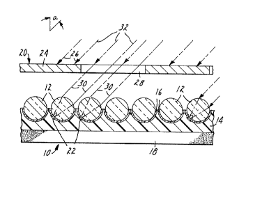
FIGURE 1 shows a microlens sheet 10 which
comprises a monolayer of transparent microspheres 12
which are partially embedded in a layer of bead binder
14, typically a polymeric material. Microlens sheeting
in which the microlenses partially protrude from the
surface is referred to as "exposed-lens" sheeting.
There is a masking layer 16 disposed at the rear surface
of each microsphere. ~he masking layer typically makes
only hemispherical contact with each of the microspheres
and does not extend between adjacent microspheres.
If the masking layer is reflective and the microspheres
have an index of refraction of approximately 1.9, the
sheeting will be retroreflective. The sheeting shown
is adapted to be adhered to an object such as a passport
with a layer of adhesive 18.
A half-tone mask 20 is used to form a set
7;~Sl~
of axial markings 22 which is visible as an integrated
directional, photographic image, an object of this
invention. The half-tone mask comprises dots or opaque
regions 24 where collimated light is not -transmitted
26 through the mask and transparent regions 28 where
collimated light is transmitted 30 through the mask
to strike the sheeting.
To form a set of axial markings which is
visible as an integrated directional, photographic
image a beam of highly collimated light 32, typically
a pulsed laser beam, is directed through the half-tone
mask 20 to the face of the sheeting 10 at an incidence
angle Alpha. Alpha is shown here to be approximately
45 . Each microsphere which the transmitted collimated
light strikes focuses the light incident upon it to
form an axial marking 22. In this type of sheeting,
each axial marking is a deformity within an individual
microlens that typically opens through the rear surface
of the microsphere and through the masking layer disposed
on the rear surface thereof. After the half-tone mask
is removed, the set of axial markings will be visible
as an integrated directional, half-tone or photographic
image within a conical field of view centered upon
the incidence angle Alpha.
FIGURE 2 shows another type of microlens
sheeting 40 in which an integrated directional,
photographic image may be formed according to this
invention. The microlens sheeting shown is "embedded-lens"
sheeting wherein spherical microlenses 42, are embedded
in a transparent protective overcoat 44, typically
a polymeric material. A masking layer 46 is disposed
behind the microspheres at the back of a transparent
spacer layer 48 which is also typically a polymeric
material. Such sheeting typically comprises a layer
of adhesive 50 by which the sheeting may be attached
to a desired object.
~273~Z
-12-
The half-tone mask 52 shown comprises
substantially reflective half-tone dots 54. Using a
reflective mask is a preferred mode of this invention
because the opaque portions of the mask reflect 56
much of the collimated beam 5~ incident upon them rather
than absorbing the energy. The collimated light 60
is directed through the half-tone mask to the face
of the sheeting at an incident angle Beta. The portion
62 of the light which is transmitted through the mask
is focused by each microsphere 42 which it strikes
to form an axial marking 64 in the masking layer 46.
After the half-tone mask 52 is removed, the set of
axial markings will be visible as an integrated
directional, photographic image within a conical field
of view centered upon the incidence angle Beta.
These FIGURES, which are not to scale, are
only descriptive and are intended to be nonlimiting.
An integrated directional photographic image may be
formed according to this invention in any sheeting
comprising a monolayer of microlenses in which a
directional image may be formed with irradiation with
a beam of collimated light.
Example
An ordinary halide continuous tone photograph
of a subject's face was converted to a 133 line half-tone
lithographic film negative. A partially reflective
half-tone negative was then prepared from the lithographic
negative according to the method disclosed in U.S.
Pat. No. 4,314,022 (Fisch).
The resulting negative was placed as a mask
on the surface of a piece of "SCOTCHLITE" Brand High
Gain Reflective Sheeting No. 7610, available from the
Minnesota Mining and Manufacturing Company of St. Paul,
Minnesota. The sheeting comprises a monolayer of closely
spaced transparent glass microspheres, substantially
1~73512
-13-
all of which have diameters of approximately 50 to
70 microns and a refractive index of approximately
1.9. The microspheres have a chemically deposited
reflective layer on the rear surface and are partially
embedded in a polymeric binder containing a black pigment.
The back side of the sheeting is coated with a pressure
sensitive adhesive which is pro-tected by a release
liner.
The mask and sheeting were then irradiated
using a Model 532Q Neodymium: Yttrium Aluminum Garnet
(Nd:YAG) Q-switched laser available from the Control
Laser Corporation of Orlando, Florida. The wavelength
of the beam emitted by the Model 532Q laser is 1.064
micrometers. The average laser power was 100 watts
at a pulse repetition rate of 10 kilohertz with a pulse
width of approximately 200 nanoseconds.
~ he laser beam was focused to provide a spot
approximately 3.5 millimeters in diameter on the mask
and sheeting. The laser beam was then scanned across
the mask and sheeting at a speed of approximately 1000
centimeters per second at an angle 15 above normal,
i.e., at -15 entrance and 0 rotation in standard
retroreflection terminology. At the end of each scan,
the sheet and mask were moved one millimeter in a direction
perpendicular to the direction of the scanning pass.
The sheeting and mask were alternately scanned and
moved until the entire area of the sheeting and mask
had been irradiated.
After the mask was removed a positive image
of the subject's face could be seen when the sheet
was viewed at the angle of incidence of the laser beam.
The integrated image was visible within a conical field
of view approximately 30 wide, the central axis of
which was the angle of incidence. In terms of tonal
gradation and resolution r the image was photographic
in appearance.
~7351~
-]~
A second image was formed by repeating the
procedure and conditions outlined above, except the
laser beam was directed at the sheeting at an angle
of incidence 15 below normal, i.e., at +15 entrance.
The integrated image was visible within a conical field
of view approximately 30 wide, the central axis of
which was the angle of incidence. As was the first
image, the second image was photographic in appearance
in terms of tonal gradation and resolution. The second
conical field of view was distinct from the conical
field in which the first image was visible. There was
no apparent interference between the two images.
This example presents only one embodiment
of the sheeting upon which this novel method may be
performed and is intended to be nonlimiting. The precise
location of the axial mar~ings formed according to
the invention, and the particular mechanism by which
they are formed may differ according to the specific
structural elements present in the sheet which is to
be made into a novel sheet of the invention, i.e.,
a sheet bearing an integrated directional, photographic
image.
~5
~ .