Language selection

Search

Patent 1273762 Summary

Third-party information liability

Some of the information on this Web page has been provided by external sources. The Government of Canada is not responsible for the accuracy, reliability or currency of the information supplied by external sources. Users wishing to rely upon this information should consult directly with the source of the information. Content provided by external sources is not subject to official languages, privacy and accessibility requirements.

Claims and Abstract availability

Any discrepancies in the text and image of the Claims and Abstract are due to differing posting times. Text of the Claims and Abstract are posted:

  • At the time the application is open to public inspection;
  • At the time of issue of the patent (grant).
(12) Patent: (11) CA 1273762
(21) Application Number: 1273762
(54) English Title: BLOW MOLDING METHOD AND APPARATUS
(54) French Title: METHODE ET DISPOSITIF DE MOULAGE PAR SOUFFLAGE
Status: Term Expired - Post Grant
Bibliographic Data
(51) International Patent Classification (IPC):
  • B29C 49/00 (2006.01)
  • B29C 49/04 (2006.01)
  • B29C 49/42 (2006.01)
  • B29C 49/48 (2006.01)
(72) Inventors :
  • SADR, CHANGIZE (Canada)
(73) Owners :
  • ABC GROUP
(71) Applicants :
  • ABC GROUP (Canada)
(74) Agent:
(74) Associate agent:
(45) Issued: 1990-09-11
(22) Filed Date: 1987-06-18
Availability of licence: N/A
Dedicated to the Public: N/A
(25) Language of filing: English

Patent Cooperation Treaty (PCT): No

(30) Application Priority Data: None

Abstracts

English Abstract


ABSTRACT OF THE DISCLOSURE
When blow molding elongated serpentine tubes or
similar articles, loading of the mold cavity with the parison
can present a problem. The parison can stick against the wall
of the mold cavity. Moreover, a large diameter parison must
be used, i.e. the parison must have a diameter equal to the total
width dimension of the article, and consequently a large volume
of flash is produced. The flash must be trimmed and recycled.
In order to avoid these problems, inserts are placed in the mold
to define portions of the mold cavity, particularly at corners.
Air under pressure is fed into passages in the outer surfaces
of the inserts and discharged through small orifices in such
inserts against the parison to guide and drive the latter fully
into the mold cavity. A vacuum can also be applied to the end
of the cavity remote from the parison entry point for drawing
the parison into the mold.


Claims

Note: Claims are shown in the official language in which they were submitted.

THE EMBODIMENTS OF THE INVENTION IN WHICH AN EXCLUSIVE
PROPERTY OR PRIVILEGE IS CLAIMED ARE DEFINED AS FOLLOWS:
1. A method of blow molding a hollow plastic article
comprising the steps of:
(a) closing a mold to define a mold cavity;
(b) introducing a parison which is smaller than the
mold cavity into one end of the mold cavity;
(c) blowing air into the mold cavity to guide the
parison during passage thereof into the mold cavity to ensure
proper loading of the parison into the mold cavity;
(d) closing said end of the mold cavity; and
(e) applying air under pressure to the interior of the
parison to blow mold the hollow article.
2. An apparatus for blow molding a hollow plastic
article comprising:
(a) mold portions for closing to define a mold cavity;
(b) nozzle means for introducing a parison into
the mold cavity;
(c) insert means in said mold portions defining orifices
for directing air under pressure against the parison to guide the
latter into the mold cavity;
(d) cylinder means for closing the mold cavity; and
(e) pin means for blowing air under pressure into the
interior of the parison to blow mold the hollow article.

3. A method according to claim 1, wherein a vacuum is
drawn on the other end of the mold cavity while air is blown
against the exterior of the parison to assist in loading of the
mold; and both ends of the mold cavity are closed following loading
thereof with the parison.
4. An apparatus according to claim 2, wherein said
mold portions include complementary mold halves.
5. An apparatus according to claim 4, wherein said
insert means includes a semicylindrical body in each said mold
half containing said orifices, said body defining a portion of
said mold cavity; and a groove in an outer surface of said body
for receiving air under pressure for discharge through said
orifices.

Description

Note: Descriptions are shown in the official language in which they were submitted.


1273762
This invention relates to the blow molding of a hollow
plastic article, and in particular to a method and apparatus for
the blow molding of elongated, serpentine, hollow articles.
In general, it is difficult to mold long, serpentine,
hollow articles. The normal procedure is to use a large diameter
parison, and the loading of such a parison into the mold presents
problems since the parison can stick to the sides of the mold
cavity. Moreover, a large diameter parison must be used, i.e. the
parison must have a diameter equal to the total width dimension of
the article, and consequently a large volume of flash is produced.
The flash must be trimmed and recycled. United States Patent
No. 4,239,474, which issued to T. Nakagawa on December 16, 1980
describes a method in which an open mold is loaded by dispensing
a parison from an extruder into the moving mold. Thereafter, the
mold is closed around the parison, and air under pressure is
applied to the interior of the parison to blow mold an elbow pipe.
The apparatus involved is, of necessity somewhat complicated and
cumbersome.
The object of the present invention is to offer a solution
to the above identified problems by providing a relatively simple
apparatus, which can be used to blow mold hollow articles having
complicated, i.e. other than straight shapes.
Accordingly, the invention relates to a method of blow
molding a hollow plastic article comprising the steps of:
(a) closing a mold to define a mold cavity;
(b) introducing a parison which is smaller than the
mold cavity into one end of the mold cavity;
(c) blowing air into the mold cavity to guide the
parison during passage thereof into the mold cavity to ensure~

~3~2
proper loading of the parison into the mold cavity;
(d) closing said one end of the mold cavity; and
(e) applying air under pressure to the interior of
the parison to blow mold the hollow article.
The invention also relates to an apparatus for blow
molding a hollow plastic article comprising:
(a) mold portions for closing to define a mold cavi~y;
(b) nozzle means for introducing a parison into the
mold cavity;
(c) insert means in said mold portions defining orifices
for directing air under pressure against the parison to guide the
latter into the mold cavity
(d) cylinder means for closing the mold cavity; and
(e) pin means for blowing air under pressure into the
interior of the parison to blow mold the hollow article.
The invention will be described in greater detail with
reference to the accompanying drawings, which illustrate a
preferred embodiment of the invention, and wherein:
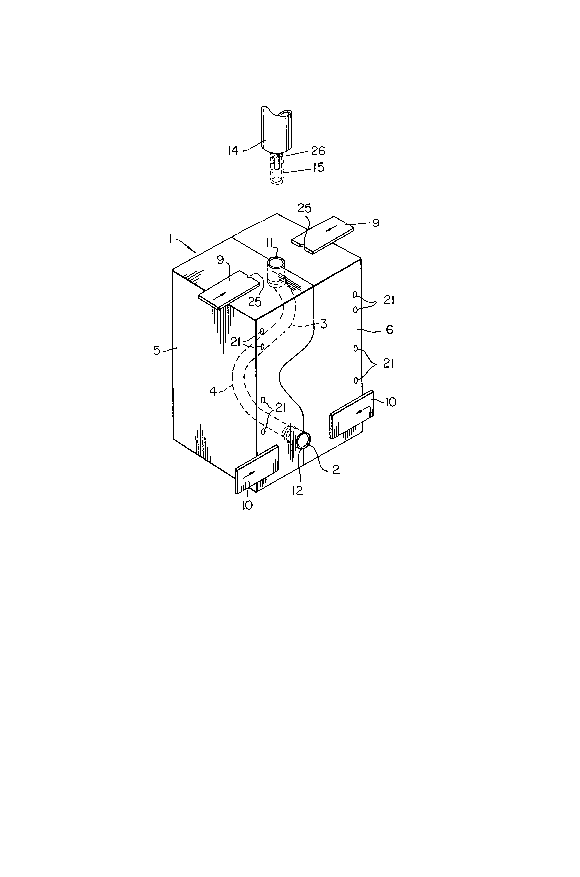
Figure 1 is a schematic, perspective view of a mold
for blow molding an elongated, serpentine tube;
Figure 2 is a partly sectioned, side view of the mold
of Fig. l; and
Figure 3 is a cross section taken generally along line
III-III of Fig. 2.
Referring to the drawings, the apparatus of the present

i2~37162
invention, which is generally indicated at 1, is designed to
blow mold an elongated, serpentine, plastic tube 2. The tube
2 shown in phantom outline in Fig. 1 has two distinct bends or
corners 3 and 4 which are in different planes.
The apparatus 1 is defined by a pair of mold halves
5 and 6, which are brought together to define a mold cavity 7
(Figs. 2 and 3). Of course, the mold cavity 7 deEines the external
configuration of the tube 2. Upper and lower pinch-off gates 9 and
10, respectively are used to close the top and bottom ends 11 and
12, respectively of the mold cavity 7. A nozzle 14 is used to
introduce a tubular parison 15 into the top end of the mold
cavity 7.
As mentioned hereinbefore, loading of the parison 15
into the mold cavity 7 can be a serious problem. With a serpentine
mold cavity 7, the possibility of sticking, i.e. intimate contact
between the parison lS and the sides of the cavity 7 is quite
distinct. In order to solve this problem, the portions of the mold
cavity 7 in the areas of the corners 3 and 4 are enlarged to receive
inserts 17, 18 and 19. Grooves are provided in the outer surfaces
of the inserts to define generally semi-cylindrical passages 20
for receiving air under pressure. The passages 20 receive air from
inlet passages 21, which pass through the mold halves 5 and 6,
and which are connected to a source of air (not shown) under
pressure. It will be appreciated that the inner surfaces of the
inserts 17, 18 and 19 define portions of the mold cavity 7.

3'7~
Air entering the passages 20 is discharged into the mold cavity
7 through orifices 23. The discharge ends of the orifices have
a small diameter (0.015 - 0.020").
In operation, the mold is closed by moving the halves
5 and 6 together to define the mold cavity 7, and the tubular
parison 15 is introduced into the open top end 11 of the mold
cavity 7. As the parison 15 moves towards the open bottom end
12 of the mold cavity 7, jets of air issuing from the orifices
23 maintain the parison 15 centered in the mold cavity and
help drive the parison towards such bottom end 12. If desired,
a vacuum can be applied to the bottom end 12 of the mold cavity
7 to facilitate loading of the parison 15 into the mold. The
combination of pressure from the orifices 23 and a vacuum ensures
proper mold loading. The nozzle 14 is withdrawn and the gates 9
and 10 are closed. Notches 25 in the top gates 9 define an
opening for a blow pin 26 (Figs. 1 and 2), which is used to
introduce air under pressure into the parison 15 to effect blow
molding.
The gates 9 and 10 are opened, the blow pin 26 is
removed, and the mold havles 5 and 6 are moved apart to open the
mold. The molded tube 2 is removed, and the mold 1 is ready
for new loading and blow molding operations.
Thus, there has been described a relatively simple method
and an apparatus for blow molding an elongated, serpentine article
without the common problem of parison sticking.

12~737~iZ
It will be appreciated that the number, distribution
and angle of the orifices with respect to the mold cavity can be
varied depending upon the shape and thickness of the article being
molded. Moreover, the air pressure on various sides of the mold
cavity can differ.
When using the existing method of molding serpentine
tubes, a large volume of flash must be removed from the articles
for recycling. The use of the present method and apparatus
is believed to be substantially less time consuming and expensive
than the existing method.
-- 5

Representative Drawing
A single figure which represents the drawing illustrating the invention.
Administrative Status

2024-08-01:As part of the Next Generation Patents (NGP) transition, the Canadian Patents Database (CPD) now contains a more detailed Event History, which replicates the Event Log of our new back-office solution.

Please note that "Inactive:" events refers to events no longer in use in our new back-office solution.

For a clearer understanding of the status of the application/patent presented on this page, the site Disclaimer , as well as the definitions for Patent , Event History , Maintenance Fee  and Payment History  should be consulted.

Event History

Description Date
Revocation of Agent Requirements Determined Compliant 2020-09-01
Inactive: Expired (old Act Patent) latest possible expiry date 2007-09-11
Inactive: IPC from MCD 2006-03-11
Inactive: Late MF processed 2002-09-20
Inactive: Office letter 2002-09-18
Grant by Issuance 1990-09-11

Abandonment History

There is no abandonment history.

Owners on Record

Note: Records showing the ownership history in alphabetical order.

Current Owners on Record
ABC GROUP
Past Owners on Record
CHANGIZE SADR
Past Owners that do not appear in the "Owners on Record" listing will appear in other documentation within the application.
Documents

To view selected files, please enter reCAPTCHA code :


To view images, click a link in the Document Description column. To download the documents, select one or more checkboxes in the first column and then click the "Download Selected in PDF format (Zip Archive)" or the "Download Selected as Single PDF" button.

List of published and non-published patent-specific documents on the CPD .

If you have any difficulty accessing content, you can call the Client Service Centre at 1-866-997-1936 or send them an e-mail at CIPO Client Service Centre.


Document
Description 
Date
(yyyy-mm-dd) 
Number of pages   Size of Image (KB) 
Claims 1993-10-07 2 39
Abstract 1993-10-07 1 21
Drawings 1993-10-07 2 41
Descriptions 1993-10-07 5 135
Representative drawing 2001-05-02 1 11
Late Payment Acknowledgement 2002-10-01 1 170
Fees 2003-09-03 1 25
Fees 2002-09-19 1 28
Correspondence 2002-09-17 1 17
Fees 2002-09-11 1 28
Fees 1999-09-07 1 24
Fees 2004-09-09 1 24
Fees 2005-09-01 1 23
Fees 2006-08-31 1 23
Fees 2000-08-31 1 28
Fees 2001-09-06 1 25
Fees 1998-09-09 1 33
Fees 1997-09-08 1 28
Fees 1995-08-09 1 28
Fees 1996-09-10 1 33
Fees 1994-09-08 1 33
Fees 1993-09-01 1 21
Fees 1992-09-09 1 21