Sélection de la langue

Search

Sommaire du brevet 1273762 

Énoncé de désistement de responsabilité concernant l'information provenant de tiers

Une partie des informations de ce site Web a été fournie par des sources externes. Le gouvernement du Canada n'assume aucune responsabilité concernant la précision, l'actualité ou la fiabilité des informations fournies par les sources externes. Les utilisateurs qui désirent employer cette information devraient consulter directement la source des informations. Le contenu fourni par les sources externes n'est pas assujetti aux exigences sur les langues officielles, la protection des renseignements personnels et l'accessibilité.

Disponibilité de l'Abrégé et des Revendications

L'apparition de différences dans le texte et l'image des Revendications et de l'Abrégé dépend du moment auquel le document est publié. Les textes des Revendications et de l'Abrégé sont affichés :

  • lorsque la demande peut être examinée par le public;
  • lorsque le brevet est émis (délivrance).
(12) Brevet: (11) CA 1273762
(21) Numéro de la demande: 1273762
(54) Titre français: METHODE ET DISPOSITIF DE MOULAGE PAR SOUFFLAGE
(54) Titre anglais: BLOW MOLDING METHOD AND APPARATUS
Statut: Durée expirée - après l'octroi
Données bibliographiques
Abrégés

Abrégé anglais


ABSTRACT OF THE DISCLOSURE
When blow molding elongated serpentine tubes or
similar articles, loading of the mold cavity with the parison
can present a problem. The parison can stick against the wall
of the mold cavity. Moreover, a large diameter parison must
be used, i.e. the parison must have a diameter equal to the total
width dimension of the article, and consequently a large volume
of flash is produced. The flash must be trimmed and recycled.
In order to avoid these problems, inserts are placed in the mold
to define portions of the mold cavity, particularly at corners.
Air under pressure is fed into passages in the outer surfaces
of the inserts and discharged through small orifices in such
inserts against the parison to guide and drive the latter fully
into the mold cavity. A vacuum can also be applied to the end
of the cavity remote from the parison entry point for drawing
the parison into the mold.

Revendications

Note : Les revendications sont présentées dans la langue officielle dans laquelle elles ont été soumises.


THE EMBODIMENTS OF THE INVENTION IN WHICH AN EXCLUSIVE
PROPERTY OR PRIVILEGE IS CLAIMED ARE DEFINED AS FOLLOWS:
1. A method of blow molding a hollow plastic article
comprising the steps of:
(a) closing a mold to define a mold cavity;
(b) introducing a parison which is smaller than the
mold cavity into one end of the mold cavity;
(c) blowing air into the mold cavity to guide the
parison during passage thereof into the mold cavity to ensure
proper loading of the parison into the mold cavity;
(d) closing said end of the mold cavity; and
(e) applying air under pressure to the interior of the
parison to blow mold the hollow article.
2. An apparatus for blow molding a hollow plastic
article comprising:
(a) mold portions for closing to define a mold cavity;
(b) nozzle means for introducing a parison into
the mold cavity;
(c) insert means in said mold portions defining orifices
for directing air under pressure against the parison to guide the
latter into the mold cavity;
(d) cylinder means for closing the mold cavity; and
(e) pin means for blowing air under pressure into the
interior of the parison to blow mold the hollow article.

3. A method according to claim 1, wherein a vacuum is
drawn on the other end of the mold cavity while air is blown
against the exterior of the parison to assist in loading of the
mold; and both ends of the mold cavity are closed following loading
thereof with the parison.
4. An apparatus according to claim 2, wherein said
mold portions include complementary mold halves.
5. An apparatus according to claim 4, wherein said
insert means includes a semicylindrical body in each said mold
half containing said orifices, said body defining a portion of
said mold cavity; and a groove in an outer surface of said body
for receiving air under pressure for discharge through said
orifices.

Description

Note : Les descriptions sont présentées dans la langue officielle dans laquelle elles ont été soumises.

1273762
This invention relates to the blow molding of a hollow
plastic article, and in particular to a method and apparatus for
the blow molding of elongated, serpentine, hollow articles.
In general, it is difficult to mold long, serpentine,
hollow articles. The normal procedure is to use a large diameter
parison, and the loading of such a parison into the mold presents
problems since the parison can stick to the sides of the mold
cavity. Moreover, a large diameter parison must be used, i.e. the
parison must have a diameter equal to the total width dimension of
the article, and consequently a large volume of flash is produced.
The flash must be trimmed and recycled. United States Patent
No. 4,239,474, which issued to T. Nakagawa on December 16, 1980
describes a method in which an open mold is loaded by dispensing
a parison from an extruder into the moving mold. Thereafter, the
mold is closed around the parison, and air under pressure is
applied to the interior of the parison to blow mold an elbow pipe.
The apparatus involved is, of necessity somewhat complicated and
cumbersome.
The object of the present invention is to offer a solution
to the above identified problems by providing a relatively simple
apparatus, which can be used to blow mold hollow articles having
complicated, i.e. other than straight shapes.
Accordingly, the invention relates to a method of blow
molding a hollow plastic article comprising the steps of:
(a) closing a mold to define a mold cavity;
(b) introducing a parison which is smaller than the
mold cavity into one end of the mold cavity;
(c) blowing air into the mold cavity to guide the
parison during passage thereof into the mold cavity to ensure~

~3~2
proper loading of the parison into the mold cavity;
(d) closing said one end of the mold cavity; and
(e) applying air under pressure to the interior of
the parison to blow mold the hollow article.
The invention also relates to an apparatus for blow
molding a hollow plastic article comprising:
(a) mold portions for closing to define a mold cavi~y;
(b) nozzle means for introducing a parison into the
mold cavity;
(c) insert means in said mold portions defining orifices
for directing air under pressure against the parison to guide the
latter into the mold cavity
(d) cylinder means for closing the mold cavity; and
(e) pin means for blowing air under pressure into the
interior of the parison to blow mold the hollow article.
The invention will be described in greater detail with
reference to the accompanying drawings, which illustrate a
preferred embodiment of the invention, and wherein:
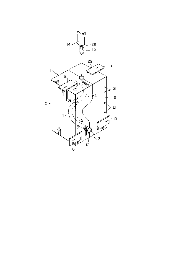
Figure 1 is a schematic, perspective view of a mold
for blow molding an elongated, serpentine tube;
Figure 2 is a partly sectioned, side view of the mold
of Fig. l; and
Figure 3 is a cross section taken generally along line
III-III of Fig. 2.
Referring to the drawings, the apparatus of the present

i2~37162
invention, which is generally indicated at 1, is designed to
blow mold an elongated, serpentine, plastic tube 2. The tube
2 shown in phantom outline in Fig. 1 has two distinct bends or
corners 3 and 4 which are in different planes.
The apparatus 1 is defined by a pair of mold halves
5 and 6, which are brought together to define a mold cavity 7
(Figs. 2 and 3). Of course, the mold cavity 7 deEines the external
configuration of the tube 2. Upper and lower pinch-off gates 9 and
10, respectively are used to close the top and bottom ends 11 and
12, respectively of the mold cavity 7. A nozzle 14 is used to
introduce a tubular parison 15 into the top end of the mold
cavity 7.
As mentioned hereinbefore, loading of the parison 15
into the mold cavity 7 can be a serious problem. With a serpentine
mold cavity 7, the possibility of sticking, i.e. intimate contact
between the parison lS and the sides of the cavity 7 is quite
distinct. In order to solve this problem, the portions of the mold
cavity 7 in the areas of the corners 3 and 4 are enlarged to receive
inserts 17, 18 and 19. Grooves are provided in the outer surfaces
of the inserts to define generally semi-cylindrical passages 20
for receiving air under pressure. The passages 20 receive air from
inlet passages 21, which pass through the mold halves 5 and 6,
and which are connected to a source of air (not shown) under
pressure. It will be appreciated that the inner surfaces of the
inserts 17, 18 and 19 define portions of the mold cavity 7.

3'7~
Air entering the passages 20 is discharged into the mold cavity
7 through orifices 23. The discharge ends of the orifices have
a small diameter (0.015 - 0.020").
In operation, the mold is closed by moving the halves
5 and 6 together to define the mold cavity 7, and the tubular
parison 15 is introduced into the open top end 11 of the mold
cavity 7. As the parison 15 moves towards the open bottom end
12 of the mold cavity 7, jets of air issuing from the orifices
23 maintain the parison 15 centered in the mold cavity and
help drive the parison towards such bottom end 12. If desired,
a vacuum can be applied to the bottom end 12 of the mold cavity
7 to facilitate loading of the parison 15 into the mold. The
combination of pressure from the orifices 23 and a vacuum ensures
proper mold loading. The nozzle 14 is withdrawn and the gates 9
and 10 are closed. Notches 25 in the top gates 9 define an
opening for a blow pin 26 (Figs. 1 and 2), which is used to
introduce air under pressure into the parison 15 to effect blow
molding.
The gates 9 and 10 are opened, the blow pin 26 is
removed, and the mold havles 5 and 6 are moved apart to open the
mold. The molded tube 2 is removed, and the mold 1 is ready
for new loading and blow molding operations.
Thus, there has been described a relatively simple method
and an apparatus for blow molding an elongated, serpentine article
without the common problem of parison sticking.

12~737~iZ
It will be appreciated that the number, distribution
and angle of the orifices with respect to the mold cavity can be
varied depending upon the shape and thickness of the article being
molded. Moreover, the air pressure on various sides of the mold
cavity can differ.
When using the existing method of molding serpentine
tubes, a large volume of flash must be removed from the articles
for recycling. The use of the present method and apparatus
is believed to be substantially less time consuming and expensive
than the existing method.
-- 5

Dessin représentatif
Une figure unique qui représente un dessin illustrant l'invention.
États administratifs

2024-08-01 : Dans le cadre de la transition vers les Brevets de nouvelle génération (BNG), la base de données sur les brevets canadiens (BDBC) contient désormais un Historique d'événement plus détaillé, qui reproduit le Journal des événements de notre nouvelle solution interne.

Veuillez noter que les événements débutant par « Inactive : » se réfèrent à des événements qui ne sont plus utilisés dans notre nouvelle solution interne.

Pour une meilleure compréhension de l'état de la demande ou brevet qui figure sur cette page, la rubrique Mise en garde , et les descriptions de Brevet , Historique d'événement , Taxes périodiques et Historique des paiements devraient être consultées.

Historique d'événement

Description Date
Exigences relatives à la révocation de la nomination d'un agent - jugée conforme 2020-09-01
Inactive : Périmé (brevet sous l'ancienne loi) date de péremption possible la plus tardive 2007-09-11
Inactive : CIB de MCD 2006-03-11
Inactive : TME en retard traitée 2002-09-20
Inactive : Lettre officielle 2002-09-18
Accordé par délivrance 1990-09-11

Historique d'abandonnement

Il n'y a pas d'historique d'abandonnement

Titulaires au dossier

Les titulaires actuels et antérieures au dossier sont affichés en ordre alphabétique.

Titulaires actuels au dossier
ABC GROUP
Titulaires antérieures au dossier
CHANGIZE SADR
Les propriétaires antérieurs qui ne figurent pas dans la liste des « Propriétaires au dossier » apparaîtront dans d'autres documents au dossier.
Documents

Pour visionner les fichiers sélectionnés, entrer le code reCAPTCHA :


Pour visualiser une image, cliquer sur un lien dans la colonne description du document. Pour télécharger l'image (les images), cliquer l'une ou plusieurs cases à cocher dans la première colonne et ensuite cliquer sur le bouton "Télécharger sélection en format PDF (archive Zip)" ou le bouton "Télécharger sélection (en un fichier PDF fusionné)".

Liste des documents de brevet publiés et non publiés sur la BDBC .

Si vous avez des difficultés à accéder au contenu, veuillez communiquer avec le Centre de services à la clientèle au 1-866-997-1936, ou envoyer un courriel au Centre de service à la clientèle de l'OPIC.


Description du
Document 
Date
(aaaa-mm-jj) 
Nombre de pages   Taille de l'image (Ko) 
Revendications 1993-10-07 2 39
Abrégé 1993-10-07 1 21
Dessins 1993-10-07 2 41
Description 1993-10-07 5 135
Dessin représentatif 2001-05-02 1 11
Quittance d'un paiement en retard 2002-10-01 1 170
Taxes 2003-09-03 1 25
Taxes 2002-09-19 1 28
Correspondance 2002-09-17 1 17
Taxes 2002-09-11 1 28
Taxes 1999-09-07 1 24
Taxes 2004-09-09 1 24
Taxes 2005-09-01 1 23
Taxes 2006-08-31 1 23
Taxes 2000-08-31 1 28
Taxes 2001-09-06 1 25
Taxes 1998-09-09 1 33
Taxes 1997-09-08 1 28
Taxes 1995-08-09 1 28
Taxes 1996-09-10 1 33
Taxes 1994-09-08 1 33
Taxes 1993-09-01 1 21
Taxes 1992-09-09 1 21