Note: Descriptions are shown in the official language in which they were submitted.
~;~73~
Inventor: Charles W. Coatnev
Title: Color Measurin~ and ContLol Device
Field of the Invention
A device for detecting the color of articles by
directing different wavelengths of light, such as red and
green, thereon and detecting the reflected light to
mea6ure the color of the articles.
Back~round of the Invention
This invention relates primarily to apparatus
especially useful in the controlling of continuously
operating proce6sing maohinery such as equipment for
blanching or roasting of peanuts, french fried potatoes,
or for peeling potatoes and the like. In such
controlled proaesses, the color of the product is
detected as it leaves the processing area. Since the
color changes with the degree of processing such as
heating, blanching, peeling and the like, detection of
the product aolor can be relied upon to lndicate whether
the procedure iB satlsfactory. Thereafter, the timing or
temperature usually can be altered to optimize the
process. Past color detectors have included a light
emittlng head whlch ls statlonary over the product. The
product is carried by a oonveyor through a heating oven
or the like and thereafter beneath the head of the color
detector. Because the product is heated and in the
process of being cooked it gives off variou6 gases and
radiates heat. If the color detecting head is exposed to
an overtemperature conditlon or if vapor carried matter
aollects on the lens lt can be rendered inoperative.
Because the product ls stacked on a conveyor for
movement through a heating prooeæsor, the distance
between the head and the produot can vary due to changes
ln the depth of the product on the conveyor. This
variance in spacing between the head and the product, as
well as the degree to which the conveyor is covered by
the product, can change significantly the detected color.
Thus, ln the case of the processor being controlled by a
. '~
- - . , .
,
.
'~ `
1 ~ 7~
signal responsive to this color, erroneou~ control
signals are generated.
It is the purpose of the present invention to
provide an improved device for reading the color of a
product.
Summary of the Inven~ion
An apparatus for measuring the color of a product
supported on a substantially horizontal surface
compri 6 ing a head with means for directing light,
usually in the red and green or possibly blue wavelength
regions, onto the product and means for deteating the
light reflected from the product. The reflected light
is changed to an electronic signal indicating the color
of the product.
To obtain an average color, the head is translated
along a horizontal path back and forth above the product.
Means are provided within the head for measuring the
temperature thereof and if the temperature exceeds a
predetermined limit, an emergency circuit is triggered to
move the head away from the product so it will not become
overheated and damaged. The temperature measured is also
used to compensate the color lndlcating signal to make it
more accurate.
Additionally, a height measuring device is
incorporated in the head to detect the distance between
the head and the product. An electrical signal
indicating this distance is used to modify the color
indicating signal to also make it more accurate and
delete any variances due to a change in the distance
between the head and product. A special combination of
light sources and lens is also provided to maximize the
effective viewing area. The light sources and lens are
temperature controlled and maintained clear of foreign
matter to enhance the life and accuracy of the
apparatus.
.
-' '' ' ' .' ' ~ ~ :' ,
~738;~)
2a
The invention therefore relates to a color ser.sor
for detecting the color of a product carried on a top
surface of a support, the sensor comprising:
5means to generate a light beam including selected
color wavelengths,
a head for transmitting the light beam onto the
product,
means supporting the head for translating movement
10over the support top surface along a path generally
parallel to the top surface,
detector means in the head for detecting the
reflected light from the product,
means to analyze the reflected light to generate an
15output signal responsive to the color of the product;
means for generating a distance signal responsive to
the distance between the product and the head, and
means to modulate the output signal responsive to
the distance signal to adjust for light changes due to
20changes in the distance between the product and the head.
The invention still further relates to a color
sensor for detecting the color of a product carried on
the top surface of a support, the senor comprising:
a color sensing head including means for directing
25light of a predetermined wavelength onto the product;
a first arm supporting at one end the color sensing
~.,
- ~ ~
1~738~V
2b
head,
a second arm rotatably fixed at one end to the other
end of the first arm,
means rotatably supporting the second arm other end;
and,
means for rotating the first arm to oscillate the
head back and forth over the support to detect an average
color of the product.
~,,,JI ':
. .
' ' . . ' ' '
': ~,, ' . - . . ' -
.,
: . :'' . .. -
' ' ' .
1~7~8~(~
Des~ri~tiQn o~ the Invention
Figure 1 i8 a perspeotive view of a color measuring
device lncorporating the present invention,
Figure 2 i6 a block diagram showing the electronic
components of the inventlon,
Flgure 3 show6 the mannsr in which the color
mea6uring head is actuated acro~s the product; and
Figure 4 is a cross sectional view of the color
detector head.
De6cri~tion of the Drawin~
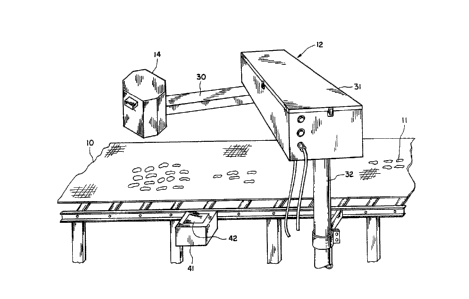
Apparatus incorporating the subject invention is
shown in Figure 1 wherein a conveyor 10 carries the
product 11, usually a food product, from an oven or other
form of processing station past a color measuring
lS apparatus 12. The color measuring apparatus tests the
color of the product as it pas6es and while not shown in
the drawing, a signal therefrom is used to adjust the
process so the color falls within a predetermined range
thereby indicating that a proper processing procedure is
2Q being achieved. Usually the temperature or belt speed is
ad~usted to optimize the process.
The product is tested by exposing it to light in a
predetermined frequency range or ranges. The reflected
light is then measured to determine the color of the
product in those ranges. For this purpose a head 14 is
suspended over the product such that light source6 lS and
16 are positioned to direct light down on the conveyor
(Fig. 4). The head comprises a housing 16 preferably
made of opague material and with a bottom wall 17
including a transparent window 17A. By proper
energization, light in predetermined frequenay ranges,
suoh as red and green is directed onto the product with
the reflected light passing baok through an aspheric lens
18A in an optical 6ystem 18 contained in a light proof
enolosure 19. The light is transmitted through a
. . - , ~
.
. .
. . . :: .
~ , , ` ` ., ' ` .
: .:
': ' : ` ` -` '
lZ738XO
dichroic reflector 20 or other means which separates the
light ranges by passing light in one range and reflecting
light in another range. Separation of the light ranges
can also be accomplished by use of fiber optics, etc.
Thus, the separated red and green ranges are represented
by the arrows 21 and 22 respectively, with an electrical
signal being generated responsive thereto by the
respective photodiodes 24 and 25. The electrical signal
generated by the photodiodes is responsive to the
magnitude of light in eaah range and thus indicates the
color of the product in these light frequencies. For a
more complete description of the operation of this
portion of a typical system, reference can be made to
United States Patent No. 4,057,352, Color Grading
Apparatus Utllizing Infra-red Light Source, issued on
November 8, 1977.
One of the problems with prior art devices is the
inability to gain an accurate average reading for the
width of the product passing thereby. If the head i8
raised sufficiently to view the overall product width it
is u6ually far enough from the product to allow other
variances ~uch as ambient light, etc. to affect the
reading. If the head is placed closer to the product a
smaller area is viewed and a less than average reading is
gained. The subject invention allows for an average
reading to be achieved for the total width of the product
stream. Another problem encountered in prior art devices
18 the damaging of the detecting head by overtemperature
conditions. Also, fumes frequently rise from the heated
product and fog up the optical components of a detecting
head and, if not remedied, will result in faulty readings
being obtained.
In accordance with the present invention, the head
is traversed across the product as the product is moved
past and for that purpose, is mounted on a supporting arm
~ F `
,
- - ~ -:
- . . ..
. ~ , . . . -
- - . .
. . - .
. - :. .
1~738~0
30 (see Figures 3 and 4) whioh is pivotally attachsd to a
second arm 31. The arm 31 i6 attached at one end to the
top of a standard 32 (Fig. 1) extending vertically and
adjacent the conveyor 11. Preferably the arm 31 extends
5 to the mid-portion of the conveyor and the arm 30 is
slightly longer than one half the width of the conveyor
to allow the head 14 to be traversed across the complete
width of the belt. A drive motor 34 positloned the top
of the standard drives chain or belt 35 extending around
a sprocket 36 on the drive motor and a second sprocket 37
fixed to the supporting spindle 30A of the arm 30. By
driving the belt 35 the arm 30 can be actuated to swing
the head 14 through an arcuate path indicated by the
dotted line 38 (Fig. 3) across the width of the conveyor
lS belt. By oscillation of the arm to move the head across
the belt continuously, an average color reading of the
product can be achieved since the head traverses the
width of the product stream as the stream proceeds past
the head. Other supports for the head will achieve equal
result6 as long as the head is traver6ed acros6 the
product6 preferably in a continuous motion.
AS an added feature of the invention there is
located within the head one or more temperature sensors
39 which indicate the temperature to which the head is
heated. When an overtemperature condition exists for the
head, a signal is transmitted back to the control to
actuate the motor 34 and move the head immediately over
a pad 40 spaced (Fig. 3) laterally from the conveyor
belt. In this manner the head is removed from the
immediate proximity of the product and the
overtemperature condition is alleviated before the head
is damaged.
AB a second feature of the invention, the device is
calibrated while in the position laterally spaced from
the conveyor and 6uch calibration is affected
,. ~. . - .
- , ~ ' . .
'' ' , ' : ' ` `
'
.' ~ " :. - '
1~738~
-- 6
periodically to assure accurate read~ngs. Calibration is
achieved by positioning one or more color calibrating
targets 42 (Fig. 3) beside the conveyor on a holder 41
over which the head can be positioned periodically.
With the head so positioned calibration can then be
achieved in a suitable manner such as is described in
United States Patent No. 4,259,020 entitled Automatic
Calibration Control for Color Grading Apparatus is 8 ued on
March 31, 1981.
Another feature of the invention allows for the
detection of ambient light and adjustment of the readant
signal from the color detecting system responsive to the
level of ambient llght. For this purpose a light
detector 43 i8 provided for detecting the ambient light
surrounding the head 14. By generating a signal
responsive to this ambient light and U8 i ng that ambient
llght signal to modify the product color signal a more
accurate indication of the product is generalized.
In accordance with another feature of the invention
the height of the head above the product is constantly
measured so as to provide for modification of the color
signal to accommodate changes in height. For this purpose
a sonlc measuring device 44 (Flg. 4) is fixed to the head
14 to provide a signal indicative of the distance between
the product and the head. One device which function
satisfactorily in thi6 manner is the Polaroid R Sonic
Position Measuring device which is available
commercially. With the signal provided by this device
the color signal is reduced or increased depending upon
the variance in the height of the head from a normal or
predetermined height above the product. The depth of the
produ,ct on the conveyor changes this height. The
mea6urlng device preferably has a long time aonstant so
as to average the height as the head translates across
the conveyor.
~, .
: . . : . : ,
- . . .
- - : -
, -
1;~73
- 7 -
In accordance wlth another feature of the invention
there is provided a lens sensor which senses the
accumulation of foreign matter on the screen 17 of the
head. For this purpose a light detector 47 is positioned
S within the head 14 (Figure 4). The light detector
8 uppl i es a signal indicating the light from the ~ource 15
and 16 reflected back from the transparent window 17A.
Thus a~ dust and the like accumulates on the viewing
6creen and begins to diminish the transparency of the
screen the reflected light increases to a predetermined
amount causing an alarm signal to be sounded indicating
that the screen should be cleaned.
Illustrated in Figure 2 is a block diagram of the
electrioal circuit of the subject invention. The sensor
head 14 is supported by the actuating arm 30 and driven
by the oscillator drive 34 which i8 under control of a
position control 51. The signals from the ~ensor head
are fed through the conductors 26 to an analog to digital
converter 52 which has the primary function of
transposing the analog signals to digital form for proper
processing in a micro computer 54. The signal from the
height sensor 44 is fed through the digltal interface 45
to this computer as well as the signals from the
temperature sensor and the lens sensor 48. Each of the
signals is utilized to modulate or modify the primary
signal received from the 6ensor head optical system. The
head sensor signal also serves to deteot operational
limits beyond which the head cignal should not be
utilized.
The micro computer 54 ~oins these signal6 for the
purpose of generating a composite signal reflecting the
respective input from those modifying conditions. The
arm position sensor 55 for detecting the general position
of the head relative to the conveyor is shown in Figure
4. This sensor comprises a disk 53 fixed to rotate with
..~'
~. ., . ' ' ~ :
. .
- - .
;~. - . - - .` `
1 ~73~
-- 8
the spindle 30A to indicate the physical positioning of
the arm 30 relative to the arm 31. An optical ~yBtem 55A
detects the rotative posltion of the disk in any of
several well known methods and supplies a signal which is
compared with that of the microcomputer to indicate a
desired position and to generate a signal for energizing
the oscillator drive 34. The position control 51 thereby
regulates the drive 34 for oscillating and positioning
the sensor head 14. A similar system is provided for the
arm 31.
The output from the microcomputer 54 is fed to a
microcomputer 58 including the serial interface 57 and a
micro processor 59. The computer 58 includes a series
of limit and sensor tables 60 which receive the height,
lS temperature and dirt sensor signals and by use of a
standard table look-up program, ~upplies a modifying
slgnal, where appropriate, to alter the color signal
received from the sensor head 14. Limits are also
provided by the limit detector 60 which includes limits
for the temperature sensor 39 and the lens sensor 48. If
such limits are exceeded an alarm 64 is energized by an
alarm output circuit 61. Additionally, a diagnostic
control is energized to analyze the system in the usual
manner. As described before, the calibration circuit 66
is also provided and a chart recorder 65 energized by a
current loop output circuit 66, and a printer 67 provide
printouts of the operation of the color measuring and
control device. Also the microprocessor 59 can supply a
signal to regulate the processor (not shown) that is
processing the product on the conveyor.
In the manner described, there is provided a color
detector which senses the overall color of the product
passing on the conveyor for generation of a signal which
ultimately is utilized for process control, etc. This
signal can be modified by the varying height of the
.
1~73~;~0
detector head relative to the product. Other variables
such as the temperature of the head and the dirt deposits
on the head screen are also detected to indicate when
remedial action should be taken.
Additional measures ar~ also taken to provide an
accurate indication of the product color. A film of air
is blown along the lower face of the transparent screen
17A as indicated by the arrow. This air is circulated
through the arms 31 and 30 for cooling the electronic
and mechanical components therein as indicatea by the
arrow6 71. The air originates at a pressured air source
(not shown) and after pas6age through the arms, flows
around the housing 19 and out of the port 72 adjacent the
transparent screen. Thus the circulated air is used for
the dual purpose of cooling the device and sweeping
aontaminated fumes from the vicinity of the screen.