Note: Descriptions are shown in the official language in which they were submitted.
~l2~7~7X
EXTENSIBLE TABLE
BACKGROUND OF THE INVENTION
I. Field of the Invention
This invention pertains to tables having folding
leaves and in particular to an improved hinge mechanism for
pivotally connecting the leaves to a table top.
II. Description of the Prior Art
In the prior art, tables having folding leaves are
well known. Common use of such tables is in the hotel
industry which uses tables having leaves which assume one
of two or three positions. The leaves may be horizontal
and flush with the table top for serving or the leaves may
be pivoted to either a down position or an up position for
transport through hotel hallways or for storage of the
table. Tables with leaves which pivot to a vertical posi-
tion above the table top are desirable in that during
transport of the table through hotel hallways, the table
leaves act to contain transported dishes, utensils and food
on the table top. In addition to having pivotable leaves,
such tables are commonly provided with a table top which
pivots on a support between a flat horizontal position and
a 90 degree displaced vertical position. Such tilting on a
support is desirable for storage of the table when not in
use. An example of such a prior art table is shown in com-
monly assigned U.S. patent 4,446,796 to Wilson et al. datedMay 8, 1984.
While a table such as described in the aforemen-
tioned U.S. patent has proven very useful in the industry,
it has been discovered that such tables may be subject to
certain disadvantages under some circumstances. As
disclosed in the aforementioned patent, the table leaves
.
.
~2~ 7~
-2-
are connected to the table top by a plurality of hinges
which include a stationary pivot member which is secured to
the table and a slide member which is secured to the leaf.
The slide member is slidably movable relative to the pivot
member but the two members are urged together by means of
an interconnecting spring. When the table leaves are to be
moved from a position flush with the table top, the leaf
must be pulled away from the table top a predetermined
stroke and either pivoted to a down position or a leaf up
position. In either event, when the leaf is pulled away
from the table top, the hinges are exposed. This can
result in undesirable consequences in that during use, such
table tops are provided with tablecloths which are commonly
white. When the leaves are pulled apart to expose the
hinges, the tablecloth can migrate into the hinge area and
become soiled. Also, the tablecloth can become pinched
when the table leaf is returned to the horizontal position.
Another problem associated with such prior art table tops
is that when the table is to be moved from the leaf up
position to a flush position, the leaf must be moved
against the urging of the spring. This can result in cum-
bersome operation of the table when attempting to move the
leaves to a position flush with the table top. Commonly
this action takes place in a hotel's guest room when the
room service table is being set up in the presence of the
hotel guests. At such time, it is very desirable from the
standpoint of the hotel to have the operation of the table
top be as smooth and graceful as possible to avoid discom-
forting the hotal guest in any manner. A still further
problem of the prior art apparatus is that when the table
leaf is moved to the down position, the table leaf extends
substantially far from the table top which requires addi-
tional space for transport or storage of the table.
.~
. ~ .. .. .
:~ Z7'~7~
various aspects of the invention are as follows:
A table comprising:
a support;
a table top;
means for connecting said table top to said support
with said top generally horizontal;
a leaf for said table top;
hinge means for hinging said leaf to said table top
with said leaf moveable between a first position
generally aligned with said table top and a second
position extending generally upwardly from said table
top, said hinge means including a first hinge member
secured to said leaf and a second hinge member, slidable
connecting means for slidably connecting said second
hinge member to said table top, pivot means for
pivotably connecting said first hinge member and said
second hinge member, said pivot means including a pivot
pin secured to said second hinge member and a slot
formed in said first hinge member and extending between
a first end and a second end, said slot sized to
slidably and rotatably received said pivot pin with said
pivot pin disposed adjacent said second end of said slot
when said leaf is in said second position: means carried
on said hinge means for locking said leaf in said second
position including means for blocking pivotal movement
of said pivot pin within said slot when said pin is
adjacent said second end of said slot and permitting
unobstructed sliding movement of said pin toward said
first end of said ~lot which said pin rotatably within
said slot at said first end:
said slidable connecting means including a bracket
fixedly secured to said table top, said second hinge
member having means cooperating with said bracket for
said second hinge member to be slidably received within
said bracket, means for urging said second hinge member
to slide within said bracket to a position with said pin
adjustment said first end of said slot; and
~, ,
2b lZ7~S7~i
said table top and said leaf present opposing edges
connected by said hinge means; said edges having
opposing generally convex surfaces disposed in abutting
relation whereby said leaf edge surfaces pivot on said
table top edge surface and said second hinge member
slides on said table top as said leaf is moved from said
first position to said second position.
A table comprising:
a support;
a table top:
means for connecting said table top to said support
with said top generally horizontal;
a leaf for said table top;
hinge means for hinging said leaf to said table top
with said leaf moveable between a first position
generally aligned with said table top and a second
position extending generally upwardly from said table
top, said hinge means including a first hinge member
secured to said leaf and a second hinge member, slidable
connecting means for slidably connecting said second
hinge member to said table top, pivot means for
pivotably connectlng sald first hinge member and said
second hinge member, sald pivot means including a pivot
pin secured to said second hlnge member and a slot
formed in said first hinge member and extending between
a first end and a second end, said slot sized to
slidably and rotatably recelve said pivot pin with said
pivot pin disposed ad;acent said second end of said slot
when said leaf is in said second position; means carried
on said hinge means for locking said leaf in said second
position including means for blocking pivotal movement
of said pivot pin within said slot when said pin is
ad~acent said second end of said slot and permitting
unobstructed sliding movement of said pin toward said
first end o~ said slot with said pin rotatably within
said 810t at said first end;
. . ,~, ,,
, ,
. . ~ - - . ,,
- .
2C ~7~7S
said slidable connecting means including a bracket
fixedly secured to said table top, said second hinge
member having means cooperating with said bracket for
said second hinge member to be slidably received within
said bracket, means for urging said second hinge member
to slide within said bracket to a position with said pin
adjacent said first end of said slot; and
said table is provided with two leaves on opposite
sides of said table top and hinged to said table top
with hinge means having second hinge members slidably
connected to said table top; second hinge members of the
first leaf aligned with second hinge members of a second
leaf in a plane coincident with sliding movement of said
second hinge members and spring means connecting said
opposing sliding members.
SUMNARY OF THE INVENTION
According to a preferred embodiment of the present
invention there is provided a table comprising a support
~ "r,~ t,~
--
-
~ ~7~
--3--
and a table top connected to the support. A leaf is pro-
vided for the table top with a hinge for connecting the
leaf to the top for movement of the leaf from a first posi-
tion aligned with the top to a second position with the
leaf generally normal to the table top. The hinge includes
a ~irst member which is secured to the leaf and a second
member connected to the table top. The first and second
members are pivotally connected and the second hinge member
is slidably connected to the table top.
More specifically, according to a preferred embo-
diment of the present invention, a pair of table leaves are
pivotally connected to opposing edges of a table top by a
p~urality of hinges. The hinges include a first hinge
member connected to the leaf and a second hinge member sli-
dably connected to the table top. Opposing sliding hinge
members on the table top are'slidably received in a channel
and connected to one another by a spring. A sliding hinge
member and an associated first hinge member are connected
by a pivot pin received within an elongated s],ot of the
first hinge member. A stop is provided secured to the
second hinge member adjacent the pivot pin and spaced
therefrom a distance to permit pivoting of the leaf when
the first hinge member is positioned with a first end of
the slot adjacent the pin. The stop prevents pivotal
motion when the first hinge member is positioned with a
second end of the slot adjacent pin.
BRIEF DESCRIPTION
OF THE DRAWING
Fig. 1 is a view in perspective of a room service
30~ table incorporating the present inventioni
Fig. 2 is a view in elevation of a room service
table incorporating the invention with its top tilted to a
storage position; '
Fig. 3 is a view taken in elevation of a room ser-
vice table incorporating the invention with the table toptilted to a use position;
12~S7S
Fig. 4 is a side elevation view of an end of a
table with the top in a use position and with table leaves
in vertical positions above the top;
Fig. 5 is an enlarged perspective view of a hinge
mechanism;
Fig. 6 is a perspective view of a channel with
latch member protruding through the channel;
Fig. 7 is a perspective view of pivot and lock
mechanisms for the table shelves; and
Figs. 8 through 10 are side elevation views
showing in sequence the movement of a leaf from a vertical
position above the table top to a vertical position beneath
the table top.
DESCRIPTION OF THE
PREFERRED EMBODIMENT
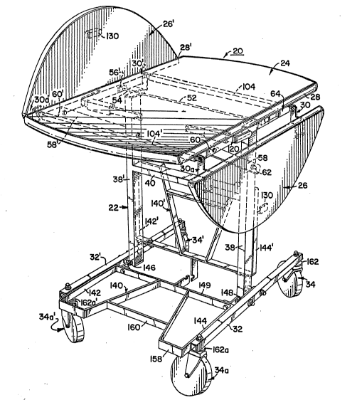
Referring to the drawings, a table 20 is shown
comprising a support 22 and a table top 24 pivotally
secured to the support 22 as will be more fully described.
A pair of extension leaves 26 and 26' are secured to oppo-
site edges 28 and 28' by hinges 30, 30a, 30' and 30a'.
Support 22 includes a pair of spaced apartparallel longitudinal base members 32 and 32' which are
provided with casters 34, 34a, 34' and 34a' which place the
base members 32 and 32' in a common horizontal plane above
a horizontal surface 36. The support 22 further includes a
pair of vertical posts 38 and 38' secured to and extending
perpendicularly upwardly away from base members 32 and 32',
respectively. Posts 38, 38' are interconnected by horizon-
tal cross member 40.
A bottom surface 24a of table top 24 is provided
with a pair of spaced apart parallel channels 42 and 42'
adjacent and parallel to edges 28 and 28', respectively.
The channels 42 and 42' are spaced apart a distance greater
than a spacing of posts 38 and 38'. As shown in Figs. 4
and 5, channels 42 and 42' are identical and a description
-
lZ7~7~
of channel 42 (as shown in Figs. 4 and 6) will suffice as a
description of channel 42'. Channel 42 comprises an extru-
sion having a U-shaped channel portion 44. A vertical
spacer portion 46 connects channel portion 44 to a horizon-
tal mounting flange 48 which is secured to the bottom sur-
face 24a by any suitable fashion such as by a plurality of
screws. Channels 42 and 42' are secured to bottom surface
24a with their respective channel portions 44 and 44'
facing one another.
Shown in Figs. 1, 2 and 5, a rod 52 is secured to
the top of the posts 38 and 38'. The rod 52 is sized such
that its free ends 54 and 54' extend beyond posts 38 and
38' and into channel portions 44 and 44', all respectively.
The free ends 54 and 54' are each provided with plastic
slides 56 and 56' which are sized to be slidably received
within channel portions 44 and 447, again all respectively.
A pair of support arms 58 and 58' are pivotally connected
to channels 42 and 42' at 60 and 60' and also pivotally
connected to posts 38 and 38' at 62 and 62'.
As shown in Figs. 5 and 6, a latch 64 is secured
to channel 42. The latch includes a latching surface 66
which is generally abutting an outer surface of channel 42.
An outwardly projecting segment 66a connects the latch sur-
~ace 66 with a handle portion 68 which is spaced away from
the channel outer surface. The latch 64 is pivotally con-
nected to channel 42 by a bolt 67 passing through channel
42 and which receives a spring 69 surrounding bolt 67 bet-
ween channel 42 and retaining nut 65. A portion of channel
portion 44 opposing latching surface 66 is broken away to
provide opening 70 extending through channel portion 44.
The opening 70 is positioned on channel portion 44 such
that the opening 70 will permit communication through the
channel 42 and expose plastic slide 56 when the table is
pivoted to the horizontal position as shown in Fig. 5. The
latch surface 66 is provided with a latching element 72
which is sized to pass through hole 70 and engage a
'
' ': ~' . '
~Z7~575
latching edge 74 of plastic slide 56. When handle portion
66 is engaged and urged toward channel 42, the handle
pivots at the bolt 67 with the latching element 72 sliding
out of latching engagement with latching edge 74. When
disengaged, the table top 20 can be tilted to a vertical
storage position.
Extension leaves 26 and 26' are attached by hinges
30, 30a, 30' and 30a', each of which are identical and the
description of hinge 30 will suffice as a description of
the others. Like parts of each of the hinges are numbered
identically except for the addition of the letter "a" or an
apostrophe to identify association with a particular hinge.
Shown best in Fig. 5 and Figs. 8-lO, hinge 30 (or hinge 30'
in Figs. 8 through lO) includes a first hinge member 80
having a mounting plate 82 to be secured to a bottom sur-
face of a leaf. A tongue 84 extends perpen-dicularly away
from the mounting plate 82 and extends longitudinally
beyond the plate 82 to a rounded free end 86. An elongated
slot 88 is provided extending through tongue 84 and having
a longitudinal direction parallel with mounting plate 82.
A first end 87 of the slot 88 which is spaced the furthest
distance from mounting plate 82 is provided coincident with
a center point of a circle which includes the contour
around free end 86.
A second hinge member 90 for connection to the
bottom surface 24a of the table top 24 tas will be des-
cribed) is provided. Second hinge member 90 is an
elongated rectangular rod sized to be slidably received
within a channel having dimensions such as that of channel
portion 44'. The second member 90 has a pivot end 92
having a hole formed therethrough for receiving a pivot pin
96 having an axis generally parallel to the edge 28 of the
table top and perpendicular to the tongue 84 of first hinge
member 80. The pin 96 extends through the hole and
elongated slot 88 pivotally joining the first hinge member
80 and second hinge member 90. The pin is secured in place
'' ' '
: ' ' '
, ' ' ~ '' '
' .
~27~S7rj
by a nut and washer 98. A stop comprising a steel bar 100
is secured to the second hinge member 90 on a side of pivot
pin 96 opposite the pivot end 92. The stop is aligned on
second member 90 to have a vertical stop surface 102 when
the second hinge member 90 is secured to the table top as
will be described. The stop surface is spaced from pivot
pin 96 a distance only slightly greater than a radius of
the rounded free end 86 of first hinge member 80. The
distance from the pivot pin 96 to the stop surface 102 is
less than a radial distance from the second end 89 of
elongated slot 88 to an end 85 of the tongue 84.
A pair of spaced apart parallel channels 104 and
104' are provided extending generally perpendicular to
edge~ 28 and 28'. The channels 104 and 104' extend almost
the entire length of the bottom surface of table top 24.
The hinges are aligned on the leaves 26 and 26' such that
hinges 30 and 30a are provided with their first hinge mem-
bers 80 and 80a secured to leaf 26. Similarly, hinges 30'
and 30a' are mounted with their respective first hinge mem-
bers 80' and 80a' secured to extension leaf 26'. The
hinges are secured to their respective leaves such that
second hinge member 90 opposes and is aligned with second
hinge member 90'. Likewise, second hinge member 90a is
opposed and aligned with second hinge member 90a'.
The channels 104 and 104' are identical in
construction with channel 42 and each provide for a channel
portion 106 and 106' respectively. The second hinge mem-
bers 90, 90a, 90' and 90a' are sized to be slidably
received within the channel portions of channels 104 and
104' such that second hinge members 90 and 90' are sli-
deably received in opposite ends of channel portion 106 of
channel 104. Likewise, second hinge members 90a and 90a'
are slidably received at opposite ends of channel portion
106' of channel I04'. Opposing ends of the second hinge
members 90, 90a, 90' and 90a' are provided with posts 108,
108a, 108' and 108a', respectively. Springs 110 and 110'
.' ~ ' .
'
:
~7g~575
--8--
are provided connecting posts 108 and 108' and posts 108a
and 108a', respectively, urging their attached second hinge
members toward one another.
As shown best in Fig~ 9, channel portions 106 and
106' are spaced away from the bottom surface of the table
top the same distance as the elongated slot 88 of the first
hinge member 80 is spaced from the bottom of the extension
leaves Such that when the leaves are in the horizontal
position flush with the table top, opposing edges of the
table top and leaves are aligned and abutting. Also, it
will be noted from the figures that the opposing edges of
the table tops and the leaves are rounded at the upper sur-
face of the leaves and table and beveled inwardly.
Best shown in Fig. 2, a pair of leaf supports 112
and 112' are provided for supporting each of leaves 26 and
26', respectively, in a position with the extension leaves
aligned with the table top 24. The leaf supports are iden-
tical and a description of leaf support 112 will suffice as
a description of leaf support 112'.
Leaf support 112 includes a channel member 114
which is an extrusion identical in cross section with chan-
nel 42. The channel 114 is aligned with its channel por-
tion extending generally transverse to the opposing edges
of the leaf 26 and the table top. The leaf support 112
includes a rod 118 sized to be slidably received within the
channel 114 and extending through an opening 120 formed
through channel 42. A free end of the support rod 118 is
provided with a handle 122 which is inwardly turned from
support rod 118 at a suitable angle therewith approximately
90 degrees, or any other suitable angle. The support rod
118 is slidable within channel 114 between a first posi-
tion with the handle 122 beneath the table top 24 to permit
free pivotal movement of the leaf 26. The support rod 118
is extensible to a second position with the handle 122
disposed beneath the leaf 26. Accurate extendible posi-
tioning of the support rod 118 is provided by a stop 124
~2~4S~5
g
secured to an inner end of the support rod 118 which abuts
the channel 114 when the support rod 118 has been extracted
a desired full stroke. In the fully extended position, the
handle 122 is aligned opposing a spacer 126 secured to a
bottom surface of the leaf 26. The spacer has a surface
opposing the handle 122 spaced from the leaf 26 a distance
~ufficient for the spacer to support the leaf on the handle
122 with the leaf 26 flush with the table top 24. A spacer
126 is provided with a sloping surface 128 opposing the
channel 42. Each of leaves 26 and 26' is provided with an
operator enqagable handle 130 and 130' secured on an under
surface thereof centrally located on an outer edge of the
bottoms of extension leaves 26 and 26', respectively.
The support 22 is provided with a pair of shelves
140 and 140' disposed on opposite sides of posts 38 and
38'. Shown best in Figs. 1 and 7, the shelves 140 and 140'
are identical and a description of one will suffice as a
description of the other. Shelf 140 includes a pair of
parallel spaced apart side walls 142 and 144 which are
pivotally secured to base members 32 and 32' by pivot pins
146 and 148. As shown, pivot pins 146 and 148 are received
within elongated slots 150 and 152 of side walls 142 and
144, respectively. The pins 146 and 148 are spaced from
vertical posts 38 and 38' a distance sufficient such that
the side walls 142 and 144 are freely pivotable about pins
146 and 148 when the pins engage first ends 151 and 153 of
elongated slots 150 and 152. When the pivot pins 146 and
148 engage the second ends 155 and 157 of the elongated
slots 150 and 152, the side walls 142 and 144 abut vertical
posts 38 and 38' thereby preventing pivotal movement of the
side walls. The side walls are connected by a cross member
149 and a second cross member 158 having a recess 160
centrally located on cross member 158. Horizontal flanges
162 of the casters provide support for the side walls 142
and 144 when the shells are rotated to the down pasition.
; . . - , .. . .
. . .
: . . ~., ., , ~ . . .
, . . . .
,, , ~ . :
, , . . - , ~
,~ . . - .
- ~ : : ' . .
1Z~7~S7~
--10--
OPERATION
The benefits of the present invention will become
apparent by reason o~ an explanation of the operation of
the apparatus of the preferred embodiment.
When the table is in its position to be used in a
hotel room, the table leaves 26 and 26' are fully extended
and flush with the table top 24. Shelves 140 and 140' may
be tilted to either an up or down position as preferred and
as indicated by the arrows of Fig. 3. When rotating the
shelves from an up position to a down position, the cross
member 158 is engaged and lifted until the pivot pins 146
engage the first ends 151 and 153 of the slots 150 and 152
at which point the shelves may be pivoted to the down posi-
tion with the side walls 142 engaging flanges 162. It
should be pointed out that in transport of the table, the
shelves may remain in the down position with the recess 160
providing adequate clearance for the angles and feet of an
operator pushing the table through a hallway.
When the table is in a position to be used in a
room, the leaves are flush with the table top and the
tongue 84 of the first hinge member 80 extends in a hori-
zontal plane generally coincident with the second hinge
member 90. In this position, the spring 120 urges opposing
hinge members 90 together with pivot pins 96 disposed
beneath the table top 24. Opposing rounded edges of the
table top and the leaves abut one another. The handle por~
tion 122 of support rod 118 engages spacer 126 maintaining
the leaves in proper alignment with the table top. Also,
the table top is tilted to its horizontal position with
latching element 72 of latch 64 engaging the latching edge
74 of the plastic slide 56 in locking engagement. Fig. 9
shows hinge 30a' when the leaf 26' is in an extended posi-
tion flush with the table top 24.
From the position described above, the leaves may
be moved to either an up position or a down position. To
move the leaf 26' to a down position, for example as shown
.
,
127~75
in Fig. 10, an operator engages the handle 130' of the leaf
with one hand and with another hand engages the handle 122'
of the support 112' pushing the support rod 118' to a posi-
tion with the handle 122' beneath the table top 24.
Gravity causes the now unsupported leaf 26' to pivot about
pins 96' and 96a' with the leaf 26' moving to a position
generally vertical with its edge disposed beneath the edge
28' of the table top since the pivot point is beneath the
table top. In such positions, the sliding hinge members
90' and 90a' are fully received within channels 104 and
104' such that the stops 100' and lOOa' abut outer surfaces
of the channels.
When the leaf is to be moved to a position with
the leaf generally vertical and above the table top (as
shown in Fig. 8 where the leaf 26' is approaching
vertical), the operator engages the leaf handle 130' and
pivots the leaf about pivot pins 96' and 96a'. As the leaf
26' approaches a generally horizontal position, the leaf
edge abuts the opposing rounded edge 28' of the table top
and continues to pivot with opposing rounded edges rolling
over one another. In this manner, the leaf and table top
edges become part of the hinge mechanism. As the table
leaf 26' continues to move to a generally vertical posi-
tion, the leaf 26 pivots at the opposing edges with the
tongues 84' and 84a' drawing the sliding hinge members 90'
and 90a' outwardly from channels 104 and 104'. The sliding
movement of the hinge members 90' and 90a' is accommodated
by the springs 110 and 110'. When the leaf is vertical,
the sliding members 90' and 90a' are in their fully
extended position and the elongated slots 88' and 88a' of
the tongues 84' and 84a' are vertical. Fig. S shows hinge
30 in fully vertical position above table top 24. At this
point as shown in Fig. 5, the tongues and leaf drop ver-
tically until the pins 96 and 96a abut the second ends 89
of the slots 88 with the edge of the leaf 26 now disposed
lower than the opposing edge 29 of the table top 24. In
12 74~ ,~S
this position, the stops 100 and lOOa engage the tongues
preventing further pivotable movement of the hinge members.
To move the leaf 26 back to a horizontal position, the
operator engages the leaf handle 130 and lifts the entire
leaf 26 until the tongues have moved such that the first
ends of the slots 88 and ~8a engage the pins 96 and 96a at
which point the spacing between the pivot pins and the
stops 100 and lOOa is sufficient to permit the rounded ends
of the tongues to pivot. As the operator pivots the leaf
back toward the horizontal position, opposing edges of the
leaf and the table roll against one another and the sliding
members 90 and 90a 90 of the hinges are urged back into the
channels 104 and 104' by the springs 110 and 110'.
If it is desired to tilt the table top from the
horizontal position to a generally vertical position, an
operator engages the handle portion 68 of the latch 64 and
urges the handle portion 68 towards the channel 42. Due to
the pivot attachment of the latch, the latching element 72
is urged out of hole 70 whereby channel portion 44 and
plastic slide 56 are freely slidable relative to one
another.
It can be seen the present invention provides
numerous advantages over the prior art. First, to move the
leaves from a vertical position above the table to a posi-
tion flush with the table, an operator need only liftagainst the weight of the table top and need not lift
against the additional force imposed by a spring as was
required in the prior art apparatus. The construction of
the table of the present invention permits relatively easy
and smooth operation of the extensible leaves in a guest
room to permit a graceful and non-disruptive set-up of a
room service table. E`urthermore, since the leaves move
from the vertical position above the table top to a flush
horizontal position with opposing edges of the table top
and leaves providing the pivot point for the pivotal
action, the hinge mechanisms are not exposed during this
~Z~ S7S
-13-
operation which avoids the possibility of soiling of the
tablecloth as well as avoiding the need for exposing the
unsightly hinge apparatus to hotel room guests. Also, when
pivotèd to the down position, the leaves are more compact
than in the prior art which facilitates movement through
narrow high traffic hotel hallways and also reduces space
requirements during storage of the table. Finally, the
apparatus is economically constructed since all channel
members may be cut from the same extrusions.
From the foregoing, it can be seen how the present
invention provides advantages not heretofore enjoyed by the
prior art. While the foregoing invention has been
described by means of a preferred embodiment, it will be
appreciated that the invention is not intended to be
limited by the specifics of the preferred embodiment and
shall include such modifications and equivalents as will
appear to those skilled in the art. Accordingly, the scope
of the present invention is intended to be limited only by
the scope of the claims as are appended hereto.