Language selection

Search

Patent 1274705 Summary

Third-party information liability

Some of the information on this Web page has been provided by external sources. The Government of Canada is not responsible for the accuracy, reliability or currency of the information supplied by external sources. Users wishing to rely upon this information should consult directly with the source of the information. Content provided by external sources is not subject to official languages, privacy and accessibility requirements.

Claims and Abstract availability

Any discrepancies in the text and image of the Claims and Abstract are due to differing posting times. Text of the Claims and Abstract are posted:

  • At the time the application is open to public inspection;
  • At the time of issue of the patent (grant).
(12) Patent: (11) CA 1274705
(21) Application Number: 1274705
(54) English Title: FLYWHEEL STARTER GEAR AND METHOD OF MAKING
(54) French Title: MECANISME DE LANCEMENT A VOLANT, ET SA FABRICATION
Status: Expired and beyond the Period of Reversal
Bibliographic Data
(51) International Patent Classification (IPC):
  • F16H 55/06 (2006.01)
  • B23P 15/14 (2006.01)
  • F16H 55/17 (2006.01)
(72) Inventors :
  • ROSELIEP, ROBERT EDWARD (United States of America)
(73) Owners :
  • UTICA ENTERPRISES, INC.
(71) Applicants :
  • UTICA ENTERPRISES, INC. (United States of America)
(74) Agent: MARKS & CLERK
(74) Associate agent:
(45) Issued: 1990-10-02
(22) Filed Date: 1987-01-07
Availability of licence: N/A
Dedicated to the Public: N/A
(25) Language of filing: English

Patent Cooperation Treaty (PCT): No

(30) Application Priority Data:
Application No. Country/Territory Date
824,377 (United States of America) 1986-01-31

Abstracts

English Abstract


ABSTRACT OF THE DISCLOSURE
A flywheel starter gear construction which includes
a strip of gear stock surrounding a flywheel disc and friction
welded to the disc in an annular weld area, the gear teeth on
the gear stock being formed by moving the assembly through a
pot broach, and the method of forming the flywheel starter gear
by selecting a measured length of gear stock, forming it into
a circle and friction welding the circular gear stock to the
periphery of a flywheel disc, then moving the welded parts
through a pot broach to form the gear teeth to serve as a starter
gear.


Claims

Note: Claims are shown in the official language in which they were submitted.

THE EMBODIMENTS OF THE INVENTION TO WHICH AN EXCLUSIVE PROPERTY
OR PRIVILEGE IS CLAIMED ARE DEFINED AS FOLLOWS:
1.
A flywheel starter gear which comprises a circular
strip of steel having a rectangular cross-section with an outer
peripheral diameter and an inner diameter, a plurality of spaced
teeth formed on the outer peripheral diameter, and a center
support disc having an annular surface friction welded to an
annular radial surface adjacent the inner diameter of said
strip, said annular radial surface of said strip having an
annular groove spaced radially outwardly of the inner diameter
of said circular strip forming an annular ridge on said surface,
said disc having an outer diameter and a surface adjacent said
outer diameter overlying said annular ridge.
2.
A method of forming a flywheel starter gear which
comprises:
(a) preparing a gear tooth strip of predetermined
length of steel stock having opposite ends and a first surface
to be friction welded to a support disc,
(b) forming said strip into a circular loop having
an outer peripheral diameter and an inner diameter,
(c) forming a center support disc with a central
support hole, a peripheral edge, and a flat, annular, radial
second surface adjacent the peripheral edge to be friction
welded to said strip,
(d) friction welding said first and second surfaces
to provide a unitized assembly about a first axis, and

(e) moving said assembly in the direction of said
first axis through a pot broach while in a plane normal to said
first axis to form teeth in the outer peripheral diameter of
said strip,
(f) forming a groove adjacent one edge of said strip
to provide an annular ridge adjacent the inner diameter of said
strip when formed into a circular loop, and positioning said
center support disc such that a portion of a surface adjacent
the periphery of the disc overlies said ridge prior to friction
welding of said strip and said disc.
3.
A method as defined in claim 2 in which said circular
loop is formed with a radial gap between the ends to serve as
a timing gap for gear formation, and orienting said assembly
circumferentially with said radial gap prior to moving said
assembly through said pot broach.

Description

Note: Descriptions are shown in the official language in which they were submitted.


74~7~35
Title
FLYWHEEL STARTER GEAR AND MET~OD OF MAKING
Field of Invention
Flywheel starter gears for automotive and other
combustion engines and method of maXing the same.
Back~round and Features of the Inverltion
~ t the present time, flywheel starter gears, which
are of relatively large diameter, are made by starting with a
strip of high carbon steel, having a square or rectangular
cross-section, and cutting it to a preset length. The strip is
then rolled into a hoop configuration with a major diameter
larger than the finished gear size, and the ends are welded
together to close the loop. The part is then annealed, coined
flat and either coir~ed to size on tha minor diameter or bored
to size or both. The closed hoops are then loaded onto an
expanding type arbor in quantities oE twenty-five or so and the
gear teeth and major diameter are cut using a hobbing machine
or gear shapiny machine.
Ater gear cutting, the closed ring is then placed in
a fixture, formed round, and centered and then weld mounted on
a flat or flanged stamped center plate.
The above-described conventional design presents
problems in that the gear rings sometime move on the arbor
during -the gear cutting resulting in poor tooth quality and
excessive pitch line runout. The end welds of the loop are

~ 7~7 0~
difficult to machine and weld separation due to excessive
centrifugal force sometimes occurs.
It is an object and ~eature of the present invention
to provide a superior ring gear assembly which is stronger than
the previous designs with more accurate gear tooth dimensions
and which is not subject to weld failures. The overall cost
is less because of the elimination of the ring butt weld and
annealing, and the sizing of the minor and major diameters.
A further object is the method or process of forming
the improved ring gear by a combination of extruded or roll
form stock, a friction welding of gear ring stock to a center
plate and a pot broaching of the gear teeth as will be described
in detail below.
The objects of the invention are thus achieved by a
starter gear made by using a circular strip of steel with a
rectangular cross-section with a plurality of spaced teeth on
the outer periphery and a center support disc with an annular
surface friction welded to an annular radial surface adjacent
the inner diameter of the strip. The annular surface may have
an annular groove spaced radially outwardly of the inner diameter
of the circular strip to form an annular ridge with the disc
overlying the ridge. The circular strip may also have a radial
gap between the ends for orienting the assembly circumferentially
to serve as a timing gap for gear formationO
.

s
Other objects and features of the invention are to
be found in the following description and claims in which the
principles o-f the lnvention are described and details of the
product and the method of forming are set forth to enable persons
skilled in the art to utilize the invention, all in connection
with the best mode presently contemplated for the invention.
Brief Descr;ption of the Drawings
DRAWIWGS accompany the disclosure and the various
views thereof may be briefly described as:
FIG. 1, a segmental view of a completed flywheel ring
gear.
Fig. 2, an end view of a gear ring section.
FIG. 3, an elevation of a ring gear strip.
-2a-

~.~7a~7~5
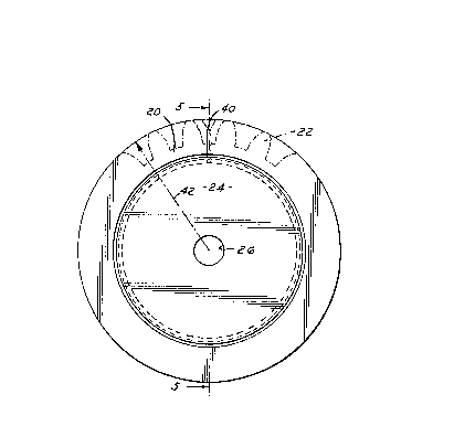
FIG. 4, an elevation of a completed ring gear and
central support plate.
FIG. 5, a sectional view on lie 5--5 of FIG. 4.
Detaile~ Description of the In~ention
and the Manner and Process of ~sinq It
With reference to the drawings, in FIG. 1, a segmental
view oE a completed flywheel ring gear is illustrated showing
an outer ring gear portion 20 having teeth 22 and a flywheel
center plate 24 with a mounting hole 25. A strip of gear tooth
ring stock is illustrated in FIGS. 2 and 3. An end view in
FIG. 2 shows a rectangular cross-section of the ring gear stock
20 with a longitudinal slot 30 above a narrowed protruding
portion 32 having a width slightly less than the overall width
of the gear stock.
The gear stock 20 is extruded or roll formed of a
suitable steel which can be subsequently induction hardened.
The groove 30 provides a surace on the portion 32 for friction
welding of the Elywheel plate as will be described. In some
instances, the groove 30 may not be required depending on the
flywheel cons-truction. It is preferable that the ring stock
be trimmed to a reasonably accurate length, and, as shown in
FIG. 3, to have the ends 34, 36 shaped so that when the ends of
the stock are brought together in a ring, as shown by the dotted
section at the left of FIG. 3, a tooth timing gap is formed at 40.
The ring stock 20 is formed in a die or fixture to
conform to the shape shown in FIG. 4 which is the weld assembly
view. The part-finished major diameter, shown by the arrow 42

~ 7 ~7 Vs
in FIG. ~, is maintained by the Eixture (not shown) and the
center ~ate stamping 24 is positioned from its center hole 26.
This entire assembly is placed into a friction welding
machine ~hich will clamp one member, either the ring 20 or the
plate 2~, and drive the other member in rotation at a proper
speed to achieve the Eriction weld whil~e exerting the proper
axial pressure between the members so as to create a friction
weld. The friction will develop heat on the narrow surface of
the portion 32 ~elow groove 30 to achieve the weld.
The welded assembly 20, 24 is now placed in a pot
broaching machine which will locate the assembly from the major
diameter and circumferentially from the tooth-timing gap 40.
This will locate the residual gap 40 in a non-
functional area of the minor diameter of an ultimate tooth space
as shown in FIG. 4. The assembly is moved axially through the
pot broach to form the proper major tooth diameter as well as
the teeth 220
After broaching, khe toothed assembly is induction
hardened and balanced to complete the part for production
assembly.
The resulting ring gear flywheel has accurate gear
teeth since the broaching process cuts each part individually
while locating from the major diameter. The described process
eliminates butt welding and annealing and internal diameter
sizing as required on the existing methods and can result in a
lighter part with a lower overall cost.

Representative Drawing
A single figure which represents the drawing illustrating the invention.
Administrative Status

2024-08-01:As part of the Next Generation Patents (NGP) transition, the Canadian Patents Database (CPD) now contains a more detailed Event History, which replicates the Event Log of our new back-office solution.

Please note that "Inactive:" events refers to events no longer in use in our new back-office solution.

For a clearer understanding of the status of the application/patent presented on this page, the site Disclaimer , as well as the definitions for Patent , Event History , Maintenance Fee  and Payment History  should be consulted.

Event History

Description Date
Inactive: IPC from MCD 2006-03-11
Time Limit for Reversal Expired 2004-10-04
Letter Sent 2003-10-02
Inactive: Entity size changed 1998-09-29
Grant by Issuance 1990-10-02

Abandonment History

There is no abandonment history.

Fee History

Fee Type Anniversary Year Due Date Paid Date
Reversal of deemed expiry 1997-10-02 1997-09-18
MF (category 1, 7th anniv.) - small 1997-10-02 1997-09-18
MF (category 1, 8th anniv.) - standard 1998-10-02 1998-09-18
MF (category 1, 9th anniv.) - standard 1999-10-04 1999-09-16
MF (category 1, 10th anniv.) - standard 2000-10-02 2000-09-19
MF (category 1, 11th anniv.) - standard 2001-10-02 2001-09-18
MF (category 1, 12th anniv.) - standard 2002-10-02 2002-09-19
Owners on Record

Note: Records showing the ownership history in alphabetical order.

Current Owners on Record
UTICA ENTERPRISES, INC.
Past Owners on Record
ROBERT EDWARD ROSELIEP
Past Owners that do not appear in the "Owners on Record" listing will appear in other documentation within the application.
Documents

To view selected files, please enter reCAPTCHA code :


To view images, click a link in the Document Description column. To download the documents, select one or more checkboxes in the first column and then click the "Download Selected in PDF format (Zip Archive)" or the "Download Selected as Single PDF" button.

List of published and non-published patent-specific documents on the CPD .

If you have any difficulty accessing content, you can call the Client Service Centre at 1-866-997-1936 or send them an e-mail at CIPO Client Service Centre.


Document
Description 
Date
(yyyy-mm-dd) 
Number of pages   Size of Image (KB) 
Cover Page 1993-10-13 1 13
Drawings 1993-10-13 1 22
Abstract 1993-10-13 1 16
Claims 1993-10-13 2 52
Descriptions 1993-10-13 5 146
Representative drawing 2001-07-09 1 11
Maintenance Fee Notice 2003-11-27 1 174
Fees 1996-09-19 1 128
Fees 1995-09-18 1 69
Fees 1994-09-19 2 106
Fees 1992-09-15 1 67
Fees 1993-09-21 1 58
Fees 1993-12-10 2 84
Correspondence 1993-11-05 1 16