Sélection de la langue

Search

Sommaire du brevet 1274705 

Énoncé de désistement de responsabilité concernant l'information provenant de tiers

Une partie des informations de ce site Web a été fournie par des sources externes. Le gouvernement du Canada n'assume aucune responsabilité concernant la précision, l'actualité ou la fiabilité des informations fournies par les sources externes. Les utilisateurs qui désirent employer cette information devraient consulter directement la source des informations. Le contenu fourni par les sources externes n'est pas assujetti aux exigences sur les langues officielles, la protection des renseignements personnels et l'accessibilité.

Disponibilité de l'Abrégé et des Revendications

L'apparition de différences dans le texte et l'image des Revendications et de l'Abrégé dépend du moment auquel le document est publié. Les textes des Revendications et de l'Abrégé sont affichés :

  • lorsque la demande peut être examinée par le public;
  • lorsque le brevet est émis (délivrance).
(12) Brevet: (11) CA 1274705
(21) Numéro de la demande: 1274705
(54) Titre français: MECANISME DE LANCEMENT A VOLANT, ET SA FABRICATION
(54) Titre anglais: FLYWHEEL STARTER GEAR AND METHOD OF MAKING
Statut: Périmé et au-delà du délai pour l’annulation
Données bibliographiques
(51) Classification internationale des brevets (CIB):
  • F16H 55/06 (2006.01)
  • B23P 15/14 (2006.01)
  • F16H 55/17 (2006.01)
(72) Inventeurs :
  • ROSELIEP, ROBERT EDWARD (Etats-Unis d'Amérique)
(73) Titulaires :
  • UTICA ENTERPRISES, INC.
(71) Demandeurs :
  • UTICA ENTERPRISES, INC. (Etats-Unis d'Amérique)
(74) Agent: MARKS & CLERK
(74) Co-agent:
(45) Délivré: 1990-10-02
(22) Date de dépôt: 1987-01-07
Licence disponible: S.O.
Cédé au domaine public: S.O.
(25) Langue des documents déposés: Anglais

Traité de coopération en matière de brevets (PCT): Non

(30) Données de priorité de la demande:
Numéro de la demande Pays / territoire Date
824,377 (Etats-Unis d'Amérique) 1986-01-31

Abrégés

Abrégé anglais


ABSTRACT OF THE DISCLOSURE
A flywheel starter gear construction which includes
a strip of gear stock surrounding a flywheel disc and friction
welded to the disc in an annular weld area, the gear teeth on
the gear stock being formed by moving the assembly through a
pot broach, and the method of forming the flywheel starter gear
by selecting a measured length of gear stock, forming it into
a circle and friction welding the circular gear stock to the
periphery of a flywheel disc, then moving the welded parts
through a pot broach to form the gear teeth to serve as a starter
gear.

Revendications

Note : Les revendications sont présentées dans la langue officielle dans laquelle elles ont été soumises.


THE EMBODIMENTS OF THE INVENTION TO WHICH AN EXCLUSIVE PROPERTY
OR PRIVILEGE IS CLAIMED ARE DEFINED AS FOLLOWS:
1.
A flywheel starter gear which comprises a circular
strip of steel having a rectangular cross-section with an outer
peripheral diameter and an inner diameter, a plurality of spaced
teeth formed on the outer peripheral diameter, and a center
support disc having an annular surface friction welded to an
annular radial surface adjacent the inner diameter of said
strip, said annular radial surface of said strip having an
annular groove spaced radially outwardly of the inner diameter
of said circular strip forming an annular ridge on said surface,
said disc having an outer diameter and a surface adjacent said
outer diameter overlying said annular ridge.
2.
A method of forming a flywheel starter gear which
comprises:
(a) preparing a gear tooth strip of predetermined
length of steel stock having opposite ends and a first surface
to be friction welded to a support disc,
(b) forming said strip into a circular loop having
an outer peripheral diameter and an inner diameter,
(c) forming a center support disc with a central
support hole, a peripheral edge, and a flat, annular, radial
second surface adjacent the peripheral edge to be friction
welded to said strip,
(d) friction welding said first and second surfaces
to provide a unitized assembly about a first axis, and

(e) moving said assembly in the direction of said
first axis through a pot broach while in a plane normal to said
first axis to form teeth in the outer peripheral diameter of
said strip,
(f) forming a groove adjacent one edge of said strip
to provide an annular ridge adjacent the inner diameter of said
strip when formed into a circular loop, and positioning said
center support disc such that a portion of a surface adjacent
the periphery of the disc overlies said ridge prior to friction
welding of said strip and said disc.
3.
A method as defined in claim 2 in which said circular
loop is formed with a radial gap between the ends to serve as
a timing gap for gear formation, and orienting said assembly
circumferentially with said radial gap prior to moving said
assembly through said pot broach.

Description

Note : Les descriptions sont présentées dans la langue officielle dans laquelle elles ont été soumises.

74~7~35
Title
FLYWHEEL STARTER GEAR AND MET~OD OF MAKING
Field of Invention
Flywheel starter gears for automotive and other
combustion engines and method of maXing the same.
Back~round and Features of the Inverltion
~ t the present time, flywheel starter gears, which
are of relatively large diameter, are made by starting with a
strip of high carbon steel, having a square or rectangular
cross-section, and cutting it to a preset length. The strip is
then rolled into a hoop configuration with a major diameter
larger than the finished gear size, and the ends are welded
together to close the loop. The part is then annealed, coined
flat and either coir~ed to size on tha minor diameter or bored
to size or both. The closed hoops are then loaded onto an
expanding type arbor in quantities oE twenty-five or so and the
gear teeth and major diameter are cut using a hobbing machine
or gear shapiny machine.
Ater gear cutting, the closed ring is then placed in
a fixture, formed round, and centered and then weld mounted on
a flat or flanged stamped center plate.
The above-described conventional design presents
problems in that the gear rings sometime move on the arbor
during -the gear cutting resulting in poor tooth quality and
excessive pitch line runout. The end welds of the loop are

~ 7~7 0~
difficult to machine and weld separation due to excessive
centrifugal force sometimes occurs.
It is an object and ~eature of the present invention
to provide a superior ring gear assembly which is stronger than
the previous designs with more accurate gear tooth dimensions
and which is not subject to weld failures. The overall cost
is less because of the elimination of the ring butt weld and
annealing, and the sizing of the minor and major diameters.
A further object is the method or process of forming
the improved ring gear by a combination of extruded or roll
form stock, a friction welding of gear ring stock to a center
plate and a pot broaching of the gear teeth as will be described
in detail below.
The objects of the invention are thus achieved by a
starter gear made by using a circular strip of steel with a
rectangular cross-section with a plurality of spaced teeth on
the outer periphery and a center support disc with an annular
surface friction welded to an annular radial surface adjacent
the inner diameter of the strip. The annular surface may have
an annular groove spaced radially outwardly of the inner diameter
of the circular strip to form an annular ridge with the disc
overlying the ridge. The circular strip may also have a radial
gap between the ends for orienting the assembly circumferentially
to serve as a timing gap for gear formationO
.

s
Other objects and features of the invention are to
be found in the following description and claims in which the
principles o-f the lnvention are described and details of the
product and the method of forming are set forth to enable persons
skilled in the art to utilize the invention, all in connection
with the best mode presently contemplated for the invention.
Brief Descr;ption of the Drawings
DRAWIWGS accompany the disclosure and the various
views thereof may be briefly described as:
FIG. 1, a segmental view of a completed flywheel ring
gear.
Fig. 2, an end view of a gear ring section.
FIG. 3, an elevation of a ring gear strip.
-2a-

~.~7a~7~5
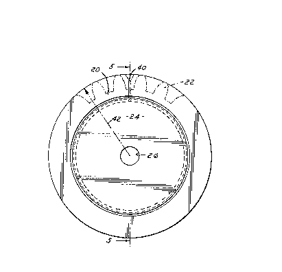
FIG. 4, an elevation of a completed ring gear and
central support plate.
FIG. 5, a sectional view on lie 5--5 of FIG. 4.
Detaile~ Description of the In~ention
and the Manner and Process of ~sinq It
With reference to the drawings, in FIG. 1, a segmental
view oE a completed flywheel ring gear is illustrated showing
an outer ring gear portion 20 having teeth 22 and a flywheel
center plate 24 with a mounting hole 25. A strip of gear tooth
ring stock is illustrated in FIGS. 2 and 3. An end view in
FIG. 2 shows a rectangular cross-section of the ring gear stock
20 with a longitudinal slot 30 above a narrowed protruding
portion 32 having a width slightly less than the overall width
of the gear stock.
The gear stock 20 is extruded or roll formed of a
suitable steel which can be subsequently induction hardened.
The groove 30 provides a surace on the portion 32 for friction
welding of the Elywheel plate as will be described. In some
instances, the groove 30 may not be required depending on the
flywheel cons-truction. It is preferable that the ring stock
be trimmed to a reasonably accurate length, and, as shown in
FIG. 3, to have the ends 34, 36 shaped so that when the ends of
the stock are brought together in a ring, as shown by the dotted
section at the left of FIG. 3, a tooth timing gap is formed at 40.
The ring stock 20 is formed in a die or fixture to
conform to the shape shown in FIG. 4 which is the weld assembly
view. The part-finished major diameter, shown by the arrow 42

~ 7 ~7 Vs
in FIG. ~, is maintained by the Eixture (not shown) and the
center ~ate stamping 24 is positioned from its center hole 26.
This entire assembly is placed into a friction welding
machine ~hich will clamp one member, either the ring 20 or the
plate 2~, and drive the other member in rotation at a proper
speed to achieve the Eriction weld whil~e exerting the proper
axial pressure between the members so as to create a friction
weld. The friction will develop heat on the narrow surface of
the portion 32 ~elow groove 30 to achieve the weld.
The welded assembly 20, 24 is now placed in a pot
broaching machine which will locate the assembly from the major
diameter and circumferentially from the tooth-timing gap 40.
This will locate the residual gap 40 in a non-
functional area of the minor diameter of an ultimate tooth space
as shown in FIG. 4. The assembly is moved axially through the
pot broach to form the proper major tooth diameter as well as
the teeth 220
After broaching, khe toothed assembly is induction
hardened and balanced to complete the part for production
assembly.
The resulting ring gear flywheel has accurate gear
teeth since the broaching process cuts each part individually
while locating from the major diameter. The described process
eliminates butt welding and annealing and internal diameter
sizing as required on the existing methods and can result in a
lighter part with a lower overall cost.

Dessin représentatif
Une figure unique qui représente un dessin illustrant l'invention.
États administratifs

2024-08-01 : Dans le cadre de la transition vers les Brevets de nouvelle génération (BNG), la base de données sur les brevets canadiens (BDBC) contient désormais un Historique d'événement plus détaillé, qui reproduit le Journal des événements de notre nouvelle solution interne.

Veuillez noter que les événements débutant par « Inactive : » se réfèrent à des événements qui ne sont plus utilisés dans notre nouvelle solution interne.

Pour une meilleure compréhension de l'état de la demande ou brevet qui figure sur cette page, la rubrique Mise en garde , et les descriptions de Brevet , Historique d'événement , Taxes périodiques et Historique des paiements devraient être consultées.

Historique d'événement

Description Date
Inactive : CIB de MCD 2006-03-11
Le délai pour l'annulation est expiré 2004-10-04
Lettre envoyée 2003-10-02
Inactive : Grandeur de l'entité changée 1998-09-29
Accordé par délivrance 1990-10-02

Historique d'abandonnement

Il n'y a pas d'historique d'abandonnement

Historique des taxes

Type de taxes Anniversaire Échéance Date payée
Annulation de la péremption réputée 1997-10-02 1997-09-18
TM (catégorie 1, 7e anniv.) - petite 1997-10-02 1997-09-18
TM (catégorie 1, 8e anniv.) - générale 1998-10-02 1998-09-18
TM (catégorie 1, 9e anniv.) - générale 1999-10-04 1999-09-16
TM (catégorie 1, 10e anniv.) - générale 2000-10-02 2000-09-19
TM (catégorie 1, 11e anniv.) - générale 2001-10-02 2001-09-18
TM (catégorie 1, 12e anniv.) - générale 2002-10-02 2002-09-19
Titulaires au dossier

Les titulaires actuels et antérieures au dossier sont affichés en ordre alphabétique.

Titulaires actuels au dossier
UTICA ENTERPRISES, INC.
Titulaires antérieures au dossier
ROBERT EDWARD ROSELIEP
Les propriétaires antérieurs qui ne figurent pas dans la liste des « Propriétaires au dossier » apparaîtront dans d'autres documents au dossier.
Documents

Pour visionner les fichiers sélectionnés, entrer le code reCAPTCHA :


Pour visualiser une image, cliquer sur un lien dans la colonne description du document. Pour télécharger l'image (les images), cliquer l'une ou plusieurs cases à cocher dans la première colonne et ensuite cliquer sur le bouton "Télécharger sélection en format PDF (archive Zip)" ou le bouton "Télécharger sélection (en un fichier PDF fusionné)".

Liste des documents de brevet publiés et non publiés sur la BDBC .

Si vous avez des difficultés à accéder au contenu, veuillez communiquer avec le Centre de services à la clientèle au 1-866-997-1936, ou envoyer un courriel au Centre de service à la clientèle de l'OPIC.


Description du
Document 
Date
(aaaa-mm-jj) 
Nombre de pages   Taille de l'image (Ko) 
Page couverture 1993-10-13 1 13
Dessins 1993-10-13 1 22
Abrégé 1993-10-13 1 16
Revendications 1993-10-13 2 52
Description 1993-10-13 5 146
Dessin représentatif 2001-07-09 1 11
Avis concernant la taxe de maintien 2003-11-27 1 174
Taxes 1996-09-19 1 128
Taxes 1995-09-18 1 69
Taxes 1994-09-19 2 106
Taxes 1992-09-15 1 67
Taxes 1993-09-21 1 58
Taxes 1993-12-10 2 84
Correspondance 1993-11-05 1 16