Language selection

Search

Patent 1275445 Summary

Third-party information liability

Some of the information on this Web page has been provided by external sources. The Government of Canada is not responsible for the accuracy, reliability or currency of the information supplied by external sources. Users wishing to rely upon this information should consult directly with the source of the information. Content provided by external sources is not subject to official languages, privacy and accessibility requirements.

Claims and Abstract availability

Any discrepancies in the text and image of the Claims and Abstract are due to differing posting times. Text of the Claims and Abstract are posted:

  • At the time the application is open to public inspection;
  • At the time of issue of the patent (grant).
(12) Patent: (11) CA 1275445
(21) Application Number: 538269
(54) English Title: VOLTAGE TESTING DEVICE
(54) French Title: DISPOSITIF DE MESURE DE TENSION
Status: Deemed expired
Bibliographic Data
Abstracts

English Abstract


ABSTRACT OF THE DISCLOSURE

A voltage monitoring device is adapted to fit within or
be mounted externally of the housing of a standard electricity
meter. The device repeatedly monitors the voltage of the mains
supply, stores data derived from the measurements for consecutive
predetermined periods, and releases the stored data upon request.


Claims

Note: Claims are shown in the official language in which they were submitted.


THE EMBODIMENTS OF THE INVENTION IN WHICH AN EXCLUSIVE
PROPERTY OR PRIVILEGE IS CLAIMED ARE DEFINED AS FOLLOWS:

1. A voltage monitoring device for use with a standard
kilowatt-hour plug-in type electricity meter having a meter
housing with protruding blades fitting into corresponding
slots in a meter base, said monitoring device comprising a
bridge member provided with a pair of spaced slots such that
said bridge member can be fitted over a pair of said
protruding blades and extend therebetween, said slots being
provided with metal contacts to establish contact with said
blades, and electronic circuitry carried by said bridge
member and connected to said metal contacts and comprising
means for repeatedly monitoring the voltage of the mains
supply, means for storing selected data derived from said
measurements for consecutive predetermined periods and means
for releasing the stored data upon request.

2. A device as claimed in claim 1 wherein the mean voltage
is stored for each predetermined period.

3. A device as claimed in claim 2 wherein the high and low
voltages are stored for each predetermined period.

4. A device as claimed in claim 1 comprising an analog-to-
digital connector for digitizing the measured voltage, a
microprocessor for deriving said data, and a digital memory
for storing said data.

5. A device as claimed in claim 4, wherein said memory
comprises a CMOS static RAM.

6. A device as claimed in claim 1, wherein said data
releasing means comprises an RS-232 interface.

7. A device as claimed in any one of claims 1 to 3, wherein
said device comprises a bridge member adapted to fit over the


protruding blades of the electricity meter with the
protruding blades passing through said slots in said bridge
member and establishing contact with metal contacts therein.

8. A voltage monitoring device for use with a standard
kilowatt-hour plug-in type electricity meter having a meter
housing with protruding blades fitting into corresponding
slots in a meter base, said monitoring device comprising a
bridge member provided with a pair of spaced slots such that
said bridge member can be fitted over a pair of said
protruding blades and extend therebetween while the
protruding blades engage corresponding slots in a meter base,
said slots being provided with metal contacts to establish
contact with said blades, and electronic circuitry carried by
said bridge member, said electronic circuitry being connected
to said metal contacts and including means for repeatedly
monitoring the voltage of the mains supply, means for storing
selected data derived from said measurements for consecutive
predetermined periods and means for releasing the stored data
upon request.

9. A device as claimed in claim 8, wherein said bridge
member is adapted to fit over the protruding blades passing
through slots in said bridge member and establishing contact
with the metal contacts therein.


Description

Note: Descriptions are shown in the official language in which they were submitted.


~ ~ ~ 54'~
The invention relates to a voltage monitoring device,
~)articlllarly aclapted for monitoring the mains vol-taye supply at
cus-tolller premises.

r; ~lectricity utilities currently monitor mains voltac3e
at certa:in pOill-tS in the distribution system, but there is no
easy and economlcal means of monitoring mains voltage at cus-tomer
prernises. Tllis informatlon is useful to give the util:lty compa-
nies the loacl marlayement information they need to plan their dis-
i0 tril)ut~ l ancl supply systems.

~ n ol)ject of this invention is to provide a device
capai)le of economically monitoring voltage supply a-t customer
prelll:ises.
:1. 1;
According to the present invention there is provided a
voltage monitoring device, said device being adapted to fit
withirl, or be mounted externally of the housing of a standard
eLectricity meter and comprising means for repeatedly monitoring
t;tle vo:ltage of the mains supply, means for storing data derived
Lrom said measurements for consecutive predetermined periods, and
mearls for re]easing the stored d~ata upon request.

In a preferred embodiment, the data stored for each
precletermined period, which may be five minutes in duration, are
l:he hiyh, low and mean voltages. The voltage measurenlents are
preferably digitized and fed to a four-bit micro computer. The
derived data are then stored in a thirty-two kilobyte CMOS static
R~M.
The device can be provided with an RS-232 interface and
associated link for connection to a commercial personal compu-ter
uporl removal from the meter housing.

The invention will now be described in more detail, by
way of example only, with reference to the accompanying drawings,


-- 1 -- I

~ 7~i4~5
~n whlch:-

Figure 1 is a block diagram of a voltage moni-toring
device in accordance with the inven-tion; and


Figure 2 illustrates the method of monitoring the
device is moun-ted on a meter.

The voltaye monitoring device sho~n in the Figure com-

pri,es a four-bit microcomputer wi-th clock 1 associated with the
3~. kilol)yte ~MOS s-tatic R~M 2. The unit is driven by a power
.~up)ly 3 der:ived from the 3-terminal mains inpu-t conslsting oE a
neu~ra:L :line ~ and two live lines 6. The power supp:Ly 3 is also
corlrlected to a back-up capacitor 7 that is capable of providing
power over an extended period of time to prevent loss of data in
Ihe everlt of a power failure.

The three mains supply terminals 4,5,6 are connected to
a voltage sensing device 8, which in turn is connected to an ana-

:log--to-digital converter 9.
The output of the 4-bit microcomputer is connected by
via a serial link to an RS-232 interface capable of con~llunicating
wi-th a host computer, such as a standard IsM PC.

The device is designed to be installed as a retrofi-t
Ullit either within or externally of the housing of a standard
type plug-in domestic electricity meter. The device is connected
to the three main supply terminals and in operation the voltage
sensor ~ continuously monitors the voltage of each live line.
Voltage measurements are normally made 60 times per second. The
measurements are conver-ted to digital form in A to D converter 9
and -the rnicrocomputer 1 derives from the voltage measurements the
higll, low and mean voltage as well as the number of missing
pulses for each five-minute interval. There thus four readings
per five-minute interval, 48 readings per hour, 672 readings per

~ 5~

day or 20,160 readings per month. These readings are stored ln
tlle 32 kilobyte non-volatile static RAM 2. The microcomputer 1
is shown as the four-bit microcomputer, but can be an eight-blt
microcolnputer.


~ fter one rnonth has elapsed, the device can be removed
~ronl the me-ter base and returned to the central station where the'
clata is -trans~erred to a commercial PC via the RS-232 link. The
device can be equipped with a radio transmi-t-ter and receiver, or
J0 some other form of remote communications device, if desired for
establishing communication with a remote sta-tion.

While the power is normally derived from the mains sup-
ply, dala inteyri-ty is maintained by the super capacit;or 7 in -the
L5 evelll. o~ power failure.
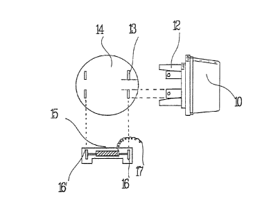
Figure 2 shows how the voltage monitoring device can be
mourlLed on a standard meter. In Figure 2, a standard residential
k:Llowa-tt/hr meter 10 has four protruding blades 12 that fit into
corresponding slots 13 in a standard meter base 14. The voltage
monitoring device is built on a bridge type plat~orm 15 with -two
spaced slots 16, 16' designed to fit over a pair of protruding
blades 12 of the meter 10. The bridge 15 mounts -the electronic
components described with reference to Figure 1. The device can
a:Lso have a floating plug-in neutral wire 17 for connection to
the neutral line running through the meter.

The slot 16,16' is equipped with metallic contacts that
brush against the protruding meter blades to establish contact
wlth those legs and supply current to the monitoring device.

The physical construction described with reference to
Flgure 2 has the important advantage that it can be quickly and
easi:Ly slipped over an existing meter. No physical modification
of -the meter is required.

~ 4~t~i

The device, which is normally in the form of a single
solicl state l-nodule, can be easily placed inside an existing util-
i-ty me-ter, or in the alternative a meter base, by a utility staff
member. In this way, a utility can easily monitor line voltage
at cus-tomer premises in any selected area. The device can easily
be -transEerred from one customer to another when voltage monitor-
ing is no longer considered necessary. At a central the data can
be easi:ly manipulated to show underlying patterns and :Line vol-
tage variations in areas served by the utili-ty.
1()


~.()


Representative Drawing
A single figure which represents the drawing illustrating the invention.
Administrative Status

For a clearer understanding of the status of the application/patent presented on this page, the site Disclaimer , as well as the definitions for Patent , Administrative Status , Maintenance Fee  and Payment History  should be consulted.

Administrative Status

Title Date
Forecasted Issue Date 1990-10-23
(22) Filed 1987-05-28
(45) Issued 1990-10-23
Deemed Expired 1994-04-24

Abandonment History

There is no abandonment history.

Payment History

Fee Type Anniversary Year Due Date Amount Paid Paid Date
Application Fee $0.00 1987-05-28
Maintenance Fee - Patent - Old Act 2 1992-10-23 $50.00 1992-10-21
Owners on Record

Note: Records showing the ownership history in alphabetical order.

Current Owners on Record
BISHOP, ROY
Past Owners on Record
None
Past Owners that do not appear in the "Owners on Record" listing will appear in other documentation within the application.
Documents

To view selected files, please enter reCAPTCHA code :


To view images, click a link in the Document Description column. To download the documents, select one or more checkboxes in the first column and then click the "Download Selected in PDF format (Zip Archive)" or the "Download Selected as Single PDF" button.

List of published and non-published patent-specific documents on the CPD .

If you have any difficulty accessing content, you can call the Client Service Centre at 1-866-997-1936 or send them an e-mail at CIPO Client Service Centre.


Document
Description 
Date
(yyyy-mm-dd) 
Number of pages   Size of Image (KB) 
Drawings 1993-10-13 2 30
Claims 1993-10-13 2 77
Abstract 1993-10-13 1 12
Cover Page 1993-10-13 1 10
Description 1993-10-13 4 144
Representative Drawing 2002-03-08 1 5
Fees 1992-10-21 1 26