Note: Descriptions are shown in the official language in which they were submitted.
12~56~6
~CKG~OUI~D ol_T~ IMv~N~rIoN
Thls invention relates in general to concrete
pavement and more particularly to a process and apparatus
for supporting and stabilizing such pavement.
Much of the pavement in this country, whether
it be at commercial, residential or institutional sites,
takes the form of concrete slabs that have been poured
directly over the underlying surface that they cover.
Sometimes the underlying surface is not stable or washes
away, in which case the slab is likely to sink. A sunken
concrete slab not only fails to align with adjacent slabs,
but often is not level or else does not possess the cor-
rect pitch.
Of course, a sunken slab may be broken apart,
removed, and thereafter be replaced with a new slab which
is poured in a like manner. Concrete worlc of this
nature is quite expensive~ and often the region in which
it must be performed is no-t accessible to heavy concrete
trucks.
Another corrective procedure, which is known
as mud jacking, involves pumping a slurry of mud and
cement at high pressure beneath the slab where it fills
voids in that region and exerts an upwardly directed
force on the slab. The force may be great enough to
elevate the slab, but even so, the process is difficult
to control. As a consequence, the slab may not rise to
the desired elevation or may acquire an undesired pitch.
;
--2--
~275~46
Furthermore, the slurry, being at high pressure, is diffi-
cult to contain and may escape from the side of the slab.
It may also find its way into sewer pipes and drains to
perhaps block them.
SUMMARY OF TIIE INVENTION
. . _ .
One of the principal objects of the present
invention is to provide a process for supporting and
stabilizing concrete slabs with a considerable amount of
control and precision. Another object is to provide a
process of the type stated which may be further used to
elevate slabs. An additional object is to provide a
process of the type stated which may be practiced at
relatively inaccessible locations. A further object is
to provide a process of the type stated which leaves the
slab with a permanent underlying support so that it is
not l-ikely to a~ain settle. S-till another object is to
provide a process of the type stated which is simple
and inexpensive to perform. Yet another object is to
provide an apparatus for stabiIizing concrete slabs.
These and other objects and advantages will become apparent
hereinafter.
-3-
:
~.Z75646
DESCI~IPTION OF' r~ DRAWIMGS
. . _ .
In the accompanying drawings which form part of
the specification and wherein like numerals and letters
refer to like par-ts wherever they occur -
Fig. 1 is a perspective view of a slab to whichthree jacking units of the present invention are attached
for stabilizing the slab;
Fig. 2 is a sectional view of the slab taken
along line 2-2 of Fig. 1 and showing one of the piers
attached to the slab;
Fig. 3 is an elevational view of the jac~ing
unit o the present invention;
Fig. 4 is a sectional view of the jacking unit
taken along line 4-4 of E'ig. 3;
Fig. 5 is a plan view of a drilling template
used in the process;
Fig. 6 is a side elevational view of the
drilling template; and
Figs. 7a, b, c, d, and e are perspective views
showing the steps sequentially for stabilizing a slab
using the process of the present invention.
DETAII.ED DESCRIPTION
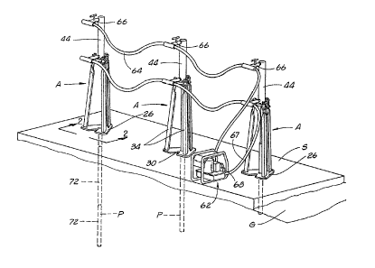
Referring now to the drawings, a sunken slab S
(Fig. 1) is elevated and stabilized with considera~le
control and precision using several jacking units A which
are~ attached to-the slab S. Actually, each jacking unit A
~L~7S~46
forces a supportin~ pier P downwardly through the slab S and
into the ground beneath the slab S until the pier P meets
with enough resistance to stabilize the slab S. In this
regard, each jacking unit A is attached to the slab S, so
that the downwardly directed force exerted by it is re-
sisted by an upwardly directed counterforce applied to
the slab S. Once enough resistance is encountered, the
jacking units A may jack against their respective piers P
to bring the slab S to the desired elevation or to merely
stabilize the slab S. The piers P are fastened to the
slab S so that they continue to support the slab S in its
elevated position.
The slab S is in mosk instances concrete paving,
such as a section of sidewalk or drlveway, or a garage
floor, or a porch deck, or the floor of a basement, or
even a floor located at grade in some building, which
has been derived in the typical manner, that is by pouring
concrete mix onto a supporting surface G and confining
the mix within a suitable form un-til it hardens. The
supporting surface G may be nothing more than dirt, or
more likely crushed stone over dirt. Dirt, however, may
not be very stable and further may wash away if not pr~perly
drained. In any even~, the dirt beneath the suppor-ting
surface G shifted, causing the surface G to drop and
the slab S along with it.
Since each jacking unit A exe~ts considerable
force on slab S, the slab S must be capable o~ accommodating
the jacking force, hopefully without cracking. To this
end the slab S should be at least about 2 1/2 inches thick
-
--5--
~L27564~i
and preferably should contain wire mesh or some other type
of reinforcement. Normally several jacking units ~ are
used at once, with the units ~ being spaced about 5 to 6
feet apart (Fig. 1). The units A should further be
located no closer than about one foot from the edge of
the slab that is to be supported.
Thus, the firs-t step in the stabilizing process
is selecting the locations at which the jac~ing units A
are to be placed. At each location a hole 2 (Fig. 2) is
drilled vertically through the slab S and then another,
although smaller, hole 4 is drilled oblique to the hole 2.
Indeed, the axis of the oblique hole 4 should intersect
the axis o~ the vertical hole 2, and the oblique hole 4
should ~urther exist on both sides of the hole 2. The
oblique hole 4 extends from the upper surface of the
sun~en slah S to the hole 2 and thence beyond the hole 2
for at least about 2 inches and preferably through the
bottom of the slab S. ~he an~Ie between the axes of the
two holes 2 and 4 should range be~ween 55 and 65 and
should preferably be about 60. In diameter, the vertical
hole 2 should be large enough to enable the pier P to pass
through it, and where a 1-5/16 inch diameter pier P is
used, 1-3/8 inches will suf~ice for the diameter of the
hole 2. The oblique hole 4 may be 1/2 inches in diameter.
The vertical hole 2 is drilled with a bit 6 (Fig. 7a),
while the oblique hole 4 is drilled with a smaller diameter
bit 8 (Fig. 7b). ~oth bits 6 and 8 are conventional
masonry or concrete bits, and as such each has a carbide
--6--
~27~646
tip and spiral flutes leading away from the tip. Each is
chucked into and turned by a conventional xotary-impact
drill.
To give the holes 2 and 4 the proper orientation
with respect to the slab S and with respect to each other,
they are drilled through a template 10 ~Figs. 5, 6, &
7a, b) which is placed over each location at which a
jacking unit A is to be attached to the slab S. The drilling
template 10 includes a flat base plate 12, which may have
a triangular configuration, and guide sleeve 14 which
is welded to the plate 12 and projects upwardly from it,
the axis of the sleeve 14 being perpendicular to the
plate 12. ~he inside diameter of the sleeve 14 is large
enough to accommodate the bit 6 while it is rotating,
yet is small enough to keep the rotating bit perpendicular
to the slab S. Of course, the base plate 12 has an aperture
at the lower end of the guide sleeve 14 to enable the
bit 6 to pass completely through the template 10 and
into the underlying slab S. In addition to the vertical
guide sleeve 14, the template 10 is furthex provided with
an oblique guide sleeve 16 which is likewise welded to the
hase plate 12, but is offset with respect to the vertical
sleeve 14 with its axls at an angle of about 30 with
respect to the plate 12. Moreover, the oblique sleeve 16
is positioned such that its axis intersects the axis of
the vertical sleeve 14 about 3 inches below the bottom surface
of the plate 12 where the included angle between the two
axes is thus 60. The inside diameter of the oblique
sleeve 16 is large enough to accommodate the bit 8 for the
--7--
~;~75~à46~
oblique hole 4 while allowing that bit to rotate, and in-
deed the interior of the sleeve 16 open~ out of the
hottom of the plate 12 through an aperture in the plate 12.
Yet, the inside diameter o~ the oblique sleeve 16 is small
enough to guide the bit 8 into the slab S at an angle of
about 30 witn respect to the surface of the slab S.
The template 10 is usec~ with a locating pin 18
(Fig. 6) that fits into the vertica] guide sleeve 14 and
is several inches longer than the sleeve 14. ~t its
upper end, the pin 18 has a handle 20 which prevents
the pin 18 from dropping completely through the sleeve 14.
In order to drill the holes 2 and 4, the drilling
template 10 is placed on the slab S at the location
selected for installation of the jacking unit A. Then
the lar~e bit 6 is inserted through the vertical guide
sleeve 14 and turned, while repeated impacts are delivered
to it (Fig. 7a). The bit 6 bores into and through the
slab S, leaving a vertical hole 2 in the slab S. When
the bit is withdrawn, the locatlng pin 18 is inserted
into the vertical ~uide sleeve 1~ and allowed to drop
into the vertical hole 2 (Fig. 7b). The pin 18 tllus
maintains the sleeve 14 in axial alignment with the hole 2.
Next, ~ith the locating pin 18 holding the
template 10 in place, the oblique hole ~ is drilled
into the slab S by inserting the other bit 8 through the
o~lique guide sleeve 16 (Fig. 7b). As the bit ~ turns
with repeated impacts being delivered to it, the bit 8 bores
into the slab S at the inclination of the sleeve 16. The bit
8 advances to the vertical hole 2, thus Eorming within
5646
the slab S the ini~ial portion of the oblique hole 4.
While the pin 18 serves to locate the template 10 with
respect to the vertical hole 2, it is desirahle to hold
the template 10 down against -the slab S while the
initial portion of the oblique hole 9 is bored, or at
least while that hole is s-tarted, because the hole 4
is at a substantial angle with respect to the slah S.
This may be achieved by having an~individual stand on the
base plate 12 o~ the template 10 while tlle drill bit 8
moves into the slab S and advances toward the vertical
hole 4.
When the small bit 8 reaches the vertical hole 2,
the locating pin 18 is removed from the vertical guide
sleeve 14, and the bit 8 is allowed to pass obliquely
through the hole 2 and thereafter bore into the slab S
at the opposite side of the hole 2, thus continuing the
oblique hole 4 beyond the opposi.te side of the vertical
hole 2. The oblique hole 4 extends for at least about
2 inches beyond the opposite side of the vertical hole 2
and preferably through the slab S, so that the oblique
hole 4 exists on both sides of -the vertical hole 2.
Once the two holes 2 and 4 are bored into the
slab S at the location selected for the jacking unit A,
the drilling template 10 is removed, and replaced ~lith
a jacking unit A that is secured firmly to the slab S
at several loc:ations around the vertical hole 2 ~Figs. 7c,
d, e~. Yet the jacking unit A does not obstruct the end
.
~ _9_
~;~7~46
of the oblique hole 4. The jacking unit A has a center
axis x, and when the unit A is properly installed, the
axis x aligns with the vertical hole 2 in the slab S.
Each jacki.ng unit A includes a base plate 26
(Figs. 3 & 4) that rests against the upper surface of
the slab S at the holes 2 and 4. The base plate 26
possesses a generally triangular conEiguration, with
each side edge measuring about 14 inches, and at its
center is provided with a circular hole 28 (Fig. 7d)
that l.ies along the center axis x and is large enough to
accommodate the pier P as ~lell as the locating pin 18.
Indeed, the latter is used to center the base plate 26
with respect to the vertical hole 2 in the slab S and
to thereby align the axis x of the jacking unit ~ with
the vertical hole 2. In addition to the center hole 28,
the base plate 12 has a slot 30 which extends inwardly
from one of its side edges toward the center hole 28.
The slot 30 is wide enough and deep enough to allow the
upper end of the oblique hole 4 to remain exposed within
the confines of the base plate 26 when the center hole
28 is aligned with the hole 2 in the slab S. The corners
of the base plate 26 are arcuate and along each corner,
the base plate has three holes 32, each being an equal
distance from the edge of the base plate 26. The holes~
32 may be 1/2 inches in diameter.
--10--
~27S6~L6
In addition to the base plate 26, the jacking
unit A includes connecting legs 34 (Figs. 3 & 4) and a
ring mount 36, the former supporting the latter in a
fixed position above the base pla-te 26 such that the
latter is concentric to the axis x and thereby directly
over the center hole 28 in the pla-te 26. More specifically,
the three legs 34 are welded to the upper surface of the
base plate 2h.slightly inwardly from the corners of that
plate, with the point of the attachment for each leg 34
being located between two of the corner holes 32 for
the corner from which it extends and immediately inwardly
from the remaining corner hole 32. The legs 34 converge
upwardly toward the axis x of the jacking unit ~ and at
their upper ends are provided with stud bolts 38. The
ring mount 36, on the other hand, has along its sides
anchor sleeves 40 through whicll the stud bolts 38 project.
Each anchor sleeve 40 is captured between two nuts 42
that are threaded onto the stud bolt 38 for that sleeve 40,
so that the ring mount 36 may be adjusted to a position
in which its axis coincides precisely with the axis x o~
the jacking unit A.
The ring mount 36 supports a double acting
hydraulic cylinder 44 (Fig. 3) such that the axis o~ the
cylindex 44 lies along and coincides with the axis x.
The cylinder 44 includes a barrel 46, which is at its
lower end welded to the ring mount 36, and also a piston
rod 48 that moves into and out of the lower end of the
barrel 46. As such the piston rod 48 projects through
~2756a~6
the ring mount 36. ~t its lower end, the piston rod 48
is fitted with an adapter 50 which is configured to fit
into and thereby engage the upper end oE the pier P,
so that a downwardly directed force may be applied to
the pier P wi-thout danger of the pier P being displaced
laterally (Fig. 7d). To this end, the adapter 50 has a
flange which is larger in diamet:er than the pier P and
a tapered nose portion which projects downwardl~ from
the flange and is large enough to fit into the hollow
interior of the pier P.
To ~ec~re the jacking unit A, to the slab so
that its cylinder 44 may be used to exert a downwardly
directed force on a pier P and an upwardly directed
counterforce on the slab S, the base plate 26 of the unit A
is placed over the vertical hole 2 with its center hole
28 aligned with the vertical hole 2. The locating pin 18
may be used to facilitate this alignment, just as it
was previously used to align the vertical guide sleeve 14
of the dri~ling template 10 with the vertical hole 2
~Fig. 7c). With the locating pin 18 in place, the base 28
is turned until the upper end o~ the oblique hole 4 is
exposed through the slot 30 in the plate 26. Then, using
the plate 26 as a template for guiding another concrete
bit 60 (Fig. 7c), anchor holes 54 are drilled into the
slab S with the bi.t 56. In particular/ a single anchor
hole 54 is bored into the slab at each corner of the base
plate 26, and that hole 54 is drilled from one of the three
corner holes 32 at the particular corner where it is located~
-12-
~7s~
Usually the center of the tllree holes 32 at each corner is
selected to guide the bit 56, that is the hole 32 directly
outwardly from the leg 34 that is attached to the corner,
but if for some reason a hole cannot be drilled through
the center hole 32, one of the side holes 32 may be used.
In any event, a separate anchor hole 54 exists beneath
each of the three corners o~ the base plate 26 for the
jacking unit A.
Then the jacking unit A is turned slightly or
else removed altogether to expose the anchor holes 54,
whereupon anchor bolts 58 (Fig. 7d) are driven into the
holes 54. The anchor holts 58 are conventional, with
each comprising nothing more than a lead anchor and a
threaded shank or stud extending from the anchor. The
anchor fits tightly in its hole 54 and indeed the bolt
58 must be driven into the hole 54 with a hammer to set
the anchor. When an outwardly directed ~orce is applied
to the bolt 58, the anchor tends to expand and seat
even more tightly within the hole 54. To avoid damaging
the threads at the upper end of the shank for the bolt 58,
a nut 60 should be turned down over those threads and
the impacts for driving the bolt 58 should be applied
against the nut 60.
Once the anchor bolts 58 are set in the slab S
around the vertical hole 2, the base plate 26 of the
jackin~ unit A is fitted over them, and as a consequence
a separate anchor bolt 58 projects through a corner hole 32
at each corner of the base plate 26 (Fig. 7d). The nuts 60,
-13-
1~7$646
which had previously been removed to allow installation
of the plate 26, are then threaded onto the anchor bolts
56 and turned down against t21e base plate 26 to insure
that the plate 26 is firmly secured to the slab S. Where
the slab S slopes in the region of the jac]cing unit A,
shims may be placed under the plate 26 to level it, for
when the plate 28 is level, the pier P will be driven
directly downwardly.
The upper ports 52 of the cylinders 44 for the
several Jacking units A are connected to a hydraulic
pump 62 (Fig. 1) through suitable hoses 64 and shut off
valves 66, there being a separate valve 66 at the upper
port 52 of each cylinder 44. The lower ports 52 of the
cylinders 44 are connected to the pump 62 through another
hose 67. The pump 62 possesses a directional valve 68
for directing pressurized fluid to either the hose 64
or the hose 67. The former of course delivers the
fluid to the upper ports 52 and causes the piston rods48
to extend, while the latter delivers it to the lower ports
52 and causes the piston rods48 to retract. Finally,
the pump 62 has a pressure control valve which may be
adjusted to vary the pressure of the fluid delivered to
the hoses 64 and 67.
Each pler P (Fig. 2) is in essence a hollow steel
pipe which is driven far enough into the ground beneath the
slab to support a considerable amount of weight - indeed more
than the weight of the portion of slab that it is assigned
to support together with any load that is on that portion
:' .
-14-
1~5~i46
of the slab S. In many instances the lower end of the
pier P will be against bed rock. The upper end of the
pier P is secured to the slab S by a pin 70 which pro-
jects from both sides of the pier P and into the
portions of the oblique hole 4 that exist on each side
of the vertical hole 2. ~he pin 70 may be a conventional
roll pin of about 1/2 inch diame-ter. It should project
from about 1-1/2" to 2" from each side o the pier P.
The pier P consists of sections 72 (Fig. 2) which
are connected end to end, with each section 72 being
short enough to fit within the jacking unit A, that is
between the base plate 26 and the adapter 50 of the
hydraulic cylinder 44 when the piston rod 48 is retracted
(Fig. 7d). Each section 72 is formed from steel tubing
and at its lower end is swagged inwardly to pro~ide a
reduced end portion 74 of a diameter small enough to fit
into the upper end of another section 72. he upper
end of each pier section 72, on the other hand, is large
enough to receive the nose of the adapter 50 on the
piston rod 48, SQ that the flange on the adapter 50
bears against the end~edge of the section 72. This enables
the cylinder 44 to apply a large downwardly directed
force to the section 72 without danger of the section 72
slipping laterally out of engagement with the adapter 50.
When one pier section 72 is driven almost entirely through
the vertical hole 2 in~ the slab S, another is engaged
with its end and also driven, there being enough sections
72 driven~end to end to produce a pier P that encounters
substantial resistance.
-15-
~ ~75646
To st~bilize and support the slab S, vertical
holes 2 and corresponding oblique holes 4 are bored into
the slab S at locations which have been selected for
the jacking units A, each set of holes 2 and 4 being
bored using the drilling template 10 as a guide for the
concrete bits 6 and 8 as previously described. Then a
jacking unit A is placed at each set of holes 2 and 4,
and using the bit 56,anchor holes 54 are bored into the
slab S at the corners of the base plate 28, with corner
holes 32 of the base plate 2% this time being used as
guides for the bit 60. Then the anchor bolts 58 are set
and the base plates 26 of the jacking units A are secured
to the slab S with those bolts 58, all in the manner
previously described.
Once the jacking units A are installed, the
upper and lower ports 52 of their hydraulic cylinders 44
are connected to the hydraulic pump 62 through the hoses
64 and 67 respectively. The directionaL valve 6~ is
set to dlrect fluid from the pump into the hose 64 that
leads to the upper ports 52. Moreover, the shut off
valves 66 for all but one of the cylinders 44 are closed,
the cylinder 44 with the one that is open being for
the unit A where the first pier P is to be driven.
Once the hoses 64 and 67 are connected and the
valves 66 and 68 are adjusted, the pump 62 is energized,
and it directs pressurized hydraulic fluid to the upper
end of the cylinder 44 on one of the jacking units A
~ith the open shut off valve 68. ~ single pier section 72
-16-
~2756a~
is inserted into the vertical hole 2 located in the slab S
at this jacking uni.t A (Fig. 7d), with the reduced end
portion 74 of that section presented downwardly. The
opposite end, which is not distorted is aligned with
the adapter 50 on the piston rod ~8 of the hydraulic
cylinder 44. As the piston rod 48 descends under the
force exerted by the pressurized hydraulic fluid admitted
into the barrel 46 through the valve 66 and upper port 52,
the nose of the adapter 50 enters the upper end of the
pier section 72, while the flange of the adapter 50 comes
against the end edge of that pier section 72. The piston
rod 48 acting through the adapter 50 thereupon exerts
a do~nwardly directed force against the pier section 72.
This force is resisted by an equal and opposite counter-
force exerted by the slab S, that counterforce being
transmitted to the cylinder 44 through the anchor bolts
56 and the plate 26, legs 34 and ring mount 36 of the
jacking unit A. The force exerted by the cylinder 44
drives the pi~r section 72 through the vertical hole 2
and into the ground beneath the slab S. When the piston
rod 48 is fully extended, only about one-half of the pier
section 72 will be in the ground. At this time, the
directional valve at the pump 62 is changed to direct
the fluid into the lower end of the cylinder 44 and
retract the piston rod 48, Next a drive rod 80 (Fig. 7e)
is placed between the adapter 50 and the upper end of the
partially driven pler section 72, the ends of the drive
-17-
~275646
rod 48 being configured to engage the adapter 50 and the
upper end of the pier section 72 such that the drive rod
80 cannot be displaced laterally. Thereupon, the
directional valve 68 is turned back to direct the
pressurized fluid to the upper port 52 and thus again
extend the piston rod 48 whereupon the piston rod 48
drives the pier section 72 almost totally into the
ground.
Next the piston rod 48 is retracted to its
fullest extent and the drive rod 80 is removed. Another
pier section 72 is then fitted into the jacking unit A,
its reduced end portion 74, which is presented downwardly,
being fitted into the upper end of the previously driven
pier section 72. The upper end of the second pier section
72t on the other hand, is aligned with the adapter 50.
The piston rod 48 again extends and drives the second
pier section 72 partially into the ground, whereupon
it is re-tracted -to thereafter extend again and drive the
second pier section 72 through a force transmitted
through the drive rod 80. This places the two sections 72
end-to-end within the ground.
Additional sections 72 are added to the pier P
and are driven in a li~e manner. When enough resistance
is encountered to lift the slab - and this may be ascertained
by monitoring the pressure delivered by the pump 62 - the
valves 66 to the cylinder 44 are closed so that the jacking
unit A continues to exert a downwardly directed force
,
-18-
~275~46
on the pier P and at tlle same time exerts an equal and
opposite lifting force on the slab S, the latter being
transmitted to the slab S through the anchor bolts 56.
The same procedure is repeated for all of the
jacking units A.
Once all of the piers p have been driven to
the extent that they encounter a predetermined amount of
resistance, which together should be enough to support
the slab S and any load it is designed to carry, the
upper port~ 52 for the cylinders 44 of all of the
jacking units A are connected simultaneously to the
pump 62 by opening all of the shut off valves 66, so
that pressurized fluid is directed simultaneously to
the cylinders 44. Each cylinder 44 thus exerts the
same amount of force on the pier P beneath it. By
thereafter operating the shut off valves 66 independently,
the pressure in the several cylinders 44 may be varied,
and indeed the jacking forces applied to the slab may be
manipulated to lift the slab S back to its original
~levation or to a desired elevation and even a desired
pitch. When the slab S reaches the desired elevation and
pitch, the cylinders 44 are blocked by closing the
valves 66, so that the slab S remains supported at that
elevation. ~he cyli~ders 44 remain in that condition
for several minutes to determine if the slab S is truly
stabilized. If a cylinder 44 loses pressure, the pier P
against which it directs its fbrce has sunk still further
and more pressure must be applied to the cylinder 44 of
its jacking unit A until the partlcular pier P is truly
stabilized and carries the weight ~ssigned to it.
--19--
~275~i46
Once the piers P are truly stabilized, each is
secured to the slab S with a roll pin 70 (E~ig. 2). As
to each pier P, this involves inser~ing a drill bit through
the oblique hole in the slab a~ that pier ~, and drilling
a hole 78 through the portion of the pier P that is within
the confines of the vertical hole 2, with the diameter
of the }-ole 78 being such that the hole 78 will snugly
receive the roll pin 70. In effect, the hole 78 forms a
connection between the two spaced apart sections of the
oblique hole 4 in the slab S. Thereupon a roll pin 70
is inserted into the oblique hole, and ~ith a drift is
driven completely through the hole 78 in the pier P -
indeed far enough to have a substantial amount of the
roll pin 70 in the portions of the oblique hole 4 on
each side of the vertical hole 2.
After the roll pin 70 is set, the pressure in
the hydraulic cylinder 44 for the jacking unit A is
released, whereupon the slab load previously transmitted
through the jac~ing unit A is transferred to the roll pin 70.
In other words, the force which supports the repositioned
and stabilized slab S is transmitted from the pier P to
the slab S at the roll pin 70.
Thereafter, the jacking unit A is removed altogether
by threading the nuts 60 off of their respective anchor
bolts 58 and lifting the jacking unit A away from the
site. The anchor bolts 56 are driven into the slab S or
are else cut off with a cutting torch. The projecting
portion of the last section 72 for the pier P is likewise
~20-
~2~5646
cut off with a torch so that the upper end of the pier P
is flush with or slightly below the upper surface of the
slab S. The holes 2, 4 and 54 which remain in the slab-S
are filled with a cement patching mix which upon hardening
brings the slab S back to its oriyinal appearance.
The piers P remain in place to support the slab S.
They prevent the slab S from sinking further, and if the
slab S has indeed been raised, they hold it in the elevated
condition. Thus, t31e piers P stabilize the slab S.
Should it be necessary to restabilize the slab S,
the roll pins 70 are merely driven through their respective
oblique holes 4, assuming that those holes 4 open out
of the bottom of the slab S. Then the foxegoing stabili-
zation process is repeated using the existing piers P
to support additional pier sections 72, if desired.
This invention is intended to cover all changes
and modifications of the example of the invention herein
chosen for purposes of the disclosure which do not
constitute departures from the spirit and scope of the
invention.
-21-