Note: Descriptions are shown in the official language in which they were submitted.
~ Z~75~ 6
- 1 -
METHOD AND APPARATUS FOR PROVIDING ADDITIONAL
SUPPORT TO SELECTED PORTIONS OF A GARMENT AND
GARMENT PRODUCED THEREBY
~` The present invention relates generally to
method and apparatus for providing additional support
or control to selected portions of a garment and the
resultant garment produced thereby and, more
particularly, to such method and apparatus which is
adapted to apply an adhesive material to selected
portions of a garment to provide a generally pleasing
aesthetic pattern as well as support or control in
such selected portions.
The reinforcing or stiffening of selected
portions of a garment, particularly an undergarment,
is generally well known. Certain undergarments,
including brassieres, corsets, yirdles and the like,
require the reinforcement or stiffening of certain
selected portions thereof in order to permit them to
function properly. This is particularly true with
respect to garments made from stretchable synthetic
knitted fabrics utilizing polyester and nylon.
For example, some brassiere kypes need some
form o~ reinforcement or stiffening elements to
provide support for the wearer. Such means include
metal underwires, plastic undershapers and stays. An
example of a brassiere selectively reinforced in the
breas~ cup area is described in United States Patent
No. 3,021,844, which issued on February 20, 1962 to
~ 27~B96
Flagg et al., and which discloses the use of a
stiffening liner in the breast cups of the brassiere.
United States Patent No. 3,750,673, which issued on
August 7, 1983 to Penrock, is similarly directed to a
brassiere having a plurality of plastic stays
positioned below the cup portion. Further, United
States Patent No. 4,558,705, which issued on December
17, 1985 to O'Boyle et al. and which is owned by the
assignee of the present application, relates to a
brassiere which includes a unique plastic support.
With the advent of composite fabrics, there
has been a trend toward incorporating stiffening
panels or inserts as part of the composite fabric to
provide selective reinforcement or stiffening. For
example, U.S. Patent No. 2,915,067, which issued on
December 1, 1959 to Bracht, is directed to a body
supporting garment having a laminated structure, which
includes a pair of flexible layers and a flexible
stiffening member therebetween. United States Patent
Nos. 4,172,002, which issued on October 23, 1979 to G.
Gluckin, is directed to a brassiere having a support
patch integrally molded into its breast cup.
Similarly, United States Patent No. 4,372,321, which
issued on February 8, 1983 to Robinson, provides a
brassiere which has a unitary molded breast cup which
includes an intermediate panel which is adhesively
bonded to the cup in order to provide additional
reinforcement or support for the cup. See also,
United States Patent Nos. 4,375,445 and 4,419,997,
which issued, respectively, on March 1, 1983 and
December 13, 1983 to R. Cole et al. Both patents are
owned by the assignee of the present application, and
are directed to brassieres having a non-stretchable
crown portion and a substantially non-strstchable
longitudinal cup portion.
Analogously, U.S. Patent No. 3,317,645,
which issued on May 2, 1967 to Nirenberg, and U.S.
~ 27~;8~
-- 3
Patent No. 3,320,346, which issued on May 16, 1967 to
Galitazki et al provide methods for forming laminated
or molded articles having these layers with the
intermediate layer made of plastic. U.S. Patent No.
3,383,263, which issued on May 14, 1968 to Storti, is
directed to a method of preparing fabric laminate, by
laminating two fabrics by means of regularly recurring
spaced geometric units of substantially dry adhesive
film sandwiched between the matting surfaces of the
fabrics.
The selective reinforcement of portions of
panties and baby pants, and methods and apparatus for
such reinforcement, are also known. For example,
United States Patent No. 3,228,401, which issued on
January 11, 1966 to Byrne, is directed to a foundation
garment having reinforced panels. In order to effect
such reinforcement, paste is applied to one or more
panels of the fabric by a silk screen technique.
Specifically, the paste is passed between the threads
of the fabric in the selected or patterned areas so as
to permit the plastic to become embedded in the
threads.
Similarly, United States Patent
No. 3,644,157, which issued on February 22, 1972 to
25 Draper, provides a method for selectively fusing a
first finished panel to an intermediate panel of
elastic material at selected locations. French Patent
No. 1,291,726, which issued on March 19, 1962 to
Girodet, is directed to undergarments, including
girdles and corsets, in which strips of stiffening
ribbons are fused to selected portions of the
garments. Analogously, United States Patent
No. 3, 502, 522, which issued on March 24, 1970 to
Adamoli, provides a method and apparatus for
manufacturing baby pants in which pieces of plastic
material are welded to the body portions thereof.
Further, United States Patent No. 3,682,738,
.
~.Z7~
~ 4
which issued on August 8, 197~ to Smith, provides
method and apparatus for depositing powdered materials
in patterned areas on textile and sheet materials.
The material is then laminated to separate fabrics
using heated, laminating rollers. Also, United States
Patent No. 3,489,154, which issued on January 13, 1970
to Kasper, Pt al. and which is owned by the assignee
of the present application, relates to a composite
sheet material used to maXe foundation-type garments
having a thin, inner panel bonded to outer ~abric
panels which include at least one thin, stretch fabric
so as to limit the s~re~chability of the laminated
fabrlc .
Other types of garments which include
reinforced or stiffened portions are the collar
portions of shirts and jackets as disclosed, for
example in U.S. Patent No. 2,975,248, which issued on
March 21, 1961 to Pfeffer, Jr. et al, and safety
helmets as disclosed, for example, in United States
Patent No. 2,956,916, which issued on October 18, 1960
to Voss et al.
Still further, apparatus and methods for
applying thermoplastic bonding materials to garments
using screen printing techniques are also well known.
For example, United States Patent No. 3,00~,849, which
issued on October 3, 1961 to Harmon et al., providPs
method and apparatus for forming a non woven ~abric.
A thermoplastic bonding material is screen printed
onto a substrate and then heatPd to fuse the material
to the substrate. Similarly, United States Patent
No. 3,676,269, which issued on July 11, 1972 to
Schaetti and which may be somewhat analogous to the
United States Patent No. 3,682,738 to Smith, provides
a method o~ laminating a powdered thermoplastic
material to a substrate which may, thereafter, be
laminated to another fabric. See also, Unitsd States
Patent Nos. 3,919,039, which issued on November 11,
~ ~S~6
1975 to Rohner; 4,096,016, which issued on June 20,
1978 to Pohl; 4,097,629, which issued on June 27, 1978
to Schneider; and 4,139,613, which issued on February
13, 1979 to Hefele, all of which provide various forms
of a laminating apparatus.
According to the present invention there is
provided a method for applying a powdered adhesive to
a selected portion of a garment, characterized by the
steps of providing a continuous conveyor system,
loading said portion at a predetermined position on
said conveyor syst~m, applying the powdered adh~sive
to said portion in a predetermined pattern, curing the
powdered adhesive, positioning a cover panel over the
powdered adhesive on said garment, fusing said cover
panel to said portion, and removing said portion from
said conveyor system.
According to a further aspect of the
invention there is provided an apparatus for applying
a thermoplastic hot melt powdered adhesive to a
selected portion of a garment, characterized in that
said apparatus comprises a continuous conveyor system
including a continuous conveyor belt, an applicator
station adapted to apply a tack adhesive to an outer
surface of said conveyor belt, a loading station
including a loading fixture provided above said
conveyor belt, said loading fixture being adapted to
orient said portion o~ said garment on said conveyor
belt, a prin~.ing station for printing the powdered
adhesive onto said portion of said garment in a
predetermined pattern, said printing station including
a printing screen containing at least one pattern
exposure in said predetermined pattern through which
the powdered adhesive may be applied directly to said
portion of said garment, a drying oven for curing the
powdered adhesive on the portion of said garment, a
loading station for applying a cover panel over the
cured adhesive, and a fusing station for ~using said
~1 27S~6
cover panel to said portion of said garment at
elevated temperature and pressure.
According to a still further aspect of the
invention there is provided a garment including a body
portion, a hot melt powdered adhesive applied in a
predetermined pattern onto a selected portion of said
body portion, and a cover panel generally
complimentary to said selected portion of said body
portion, said powdered adhesive being fused to said
cover panel and said body portion so as to
interconnect said cover panel and said body portion
thereby creating a control area adapted to selectively
reduce the stretchability of said body portion, said
powdered adhesive providing an aesthetically pleasing
pattern visible through said body portion.
To this end, the method and apparatus serve
to apply a powdered adhesive to selected portions of a
garment. The selected portions are initially placed
on a conveyor system through a loading fixture and the
adhesive is thereupon screen printed onto the selected
portions in a predetermined pattern. Thereafter, the
adhesive is cured in a drying oven and permitted to
cool. A cover panel is then placed over the adhesive
and fused to the garment at elevated temperature and
pressure.
The resultant garment possesses the unique
combination of selective control or support, while
retaining fit, shaping and performance
characteristics, and an extremely pleasing aesthetic
appearance.
The invention will now be described with
refer~nce to the accompan~ing drawings, in which
Fig. 1 is a side elevational view of t~e
apparatus of the present invention;
Fig. 2 is a top view of the apparatus of
Fig. l;
Fig. 3 is a front view of a pa~y article
~1 ~7~-~96
produced according to the teachings of the present
invention;
Fig. 4 is a cutaway view of the panty of
~ig. 3;
Fig. 5 is a sectional view taken along line
5~5 of Fig. 3;
Figs. 6A-6C illustrate alternatiYe patterns
which may be used in the panty of Fig. 3; and
Figs. 7A-7B is a front view of a portion of
a conventional brassiere having selectively supported
portions in aesthetically pleasing patterns produced
according to the teachings o~ the present invention.
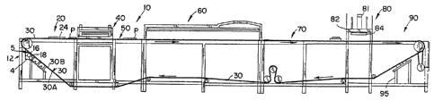
The apparatus of the present invention, as
illustrated in Figs. 1 and 2, comprises a multi-stage
conveyor device, indicated generally by reference
numeral 10, which includes a series of stations
starting from an applicator station 12 and progressing
downstream to a cleaning station 95. Multi-stage
conveyor device 10 also includes a continuous conveyor
belt 30 fabricated from a material which should be
capable of withstanding heat in excess of at least
about 350F. In this regard, conveyor belt 30, which
includes outer and inner surfaces 3OA and 3OB,
respectively, is pre~erably fabricated from spun
polyester coated with butyl rubber. In a particularly
pre~erred embodiment, conveyor belt 30 is ~abricated
from a three ply, 8.9 oz./yd 2 spun polyester with a
0.094" thick coating of butyl rubber.
Applicator station 12 includes tack adhesive
applicator means 15 adapted to apply a relatively thin
layer of a belt tack adhesive to the outer surface 3Oa
of the conveyor belt 30.
The conveyor device 10 further includes a
loading station 20 positioned downstream from the
applicator station 12 at which a loading fixture 24 is
positioned above the conveyor belt 30. Loading
~ixture 24 is adapted to facilikate and properly
~ ~S8~
orient placement of base panel or panels P onto the
conveyor belt 30. Typically, each base panel
comprises the body portion of the garment to be
produced. Loading fixture 24 includes at least one
and, preferably, two or more pattern portions 26, each
of a complimentary size and shape to the base panel P.
Each base panel P is fed through the pattern portions
26 o~ the loading fixture 24 directly snto the
conveyor belt 30 in proper alignment and orientation
for subsequent operations.
The base panels P are maintained in such
proper alignment and orientation during subsequent
operations due to the tack adhesive present on the
outer surface 30A of the conveyor belt 30, and if
desired, additional manual pressure may be applied at
the loading station 20 to smooth out the base panels P
prior to further processing.
Tack adhesive applicator means 15 include a
vessel 14 for storing a suitable quantity of a tack
adhesive, a transfer roller 16 communicating between
the quantity of tack adhesive in the vessel and the
outer surface 3OA o~ the conveyor belt 30, and a
doctor blade 18 for removing any excess tack adhesive
from the outer surface and for smoothing out the tack
adhesive which was applied to the conveyor belt 30.
The tack adhesive selected should perform
equally well with garments made from cellulosic and
synthetic fabrics and must be capable of being easily
removed from the conveyor belt 30 using conventional
water~ belt washing devices (not shown) which are
positioned at cleaning station 95. For this reason,
the tack adhesive applied to the conveyor belt 30 at
the applicator station 12 is, preferably, a water
soluble tack adhesive with excellent green tack
properties so as to hold the garment in register with
the conveyor belt 30 immediately upon contact
therewith. It ha~ been ~ound that a preferred typ~ of
1 ~7~
tack adhesive is a polyvinyl alcohol based tack
adhesive such as, for example, PRINTING ADHESIVE 500
which is available through the Polymer Industries
subsidiary of Morton Thiokol, Inc. In a preferred
embodiment, the PRINTING AD~ESIVE 500 is diluted with
water in between a 2:1 and a 5:1 ratio of water to
tack adhesive.
After the base panels P are placed in proper
alignment on the conveyor belt 30 at the loading
sta~ion 20, they then travel further downstream to a
printing station 40 where a garment adhesive is screen
printed onto the base panels P in a predetermined
pattern. Printing station 40 includes a printing
frame 42 which supports a printing screen 44 and at
least one and, preferably, two reciprocating doctor
blades 46A and 46B. Printing station 40 also includes
conventional means (not shown) for supplying the
garment adhesive to the printing frame 42. The supply
means, preferably in the form of a supply trough
attached to an external source of garment adhesive,
must be capable of introducing suitable ~uantities of
the garment adhesive into the printing frame 42. At
the time of application, the garment adhesive must be
heated to ambient temperature, i.eO, between about
6sF. and about 80F.
The printing screen 44 includes one or mor~
pattern exposures 45 of complimentary configuration
and shaped to the pattern to be printed onto the base
panels P.
~he reciprocating doctor blades 46A and 46B
provided in printing station 40 are adapted to travel
across the printing frame 42, preferably in a
direction perpendicular to the direction of movement
of the conveyor belt 30. Travel of the doctor blades
46A and 46B forces the garment adhesive through the
pattern exposures 45 in the printing screen 44 thereby
printing the garment adhesive directly onto the base
-- 10 --
panel P positioned on the conveyor belt 30 below the
pattern exposures 45.
In a preferred embodiment, the two doctor
blades 46A and 46B are reciprocating. During the
forward stroke of the blades 46A and 46B, the rear
blade 46B spreads out the garment adhesive over the
surface o~ the screen 44 and, upon its return stroke,
the front doctor blade 46A forces the adhesive through
the pattern exposures 45 in the screen 44 directly
over the base panels P. During its forward stroke,
the front doctor blade 46A does not touch the screen
44 and, likewise, during its return stroke, the rear
doctor blade 46B does not touch the screen. By such
reciprocating action, the doctor blades 46A and 46B
are able to more evenly apply the garment adhesive to
the base panels P.
It will be appr~ciated that the pattern
exposures 45 of the printing screen 44 can assume
numerous sizes, shapes and configurations depending
upon the specific application and such configurations
can be changed by changing the printing screen 44
employed. It will further be appreciated that the
actual thickness of the garment adhesive printed onto
the base panels P varies as a function of the amount
of garment adhesive in the printing ~rame 42, and the
pxessure and duration of movement of the doctor blades
46A and 46B.
A prefPrred thickness of the garment
adhesive which is printed or applied onto the base
panels P at printing station 40 is between about
0.010"" and about 0.020" and will vary according to
the amount o~ control or support desired in the
finished garment. For example, when only light
control is required, the thickness of the adhesive
should be between about 0.010" and about 0.015ll and,
when greater control or support is desired, the
thickness of the adhesive should increase to between
~I Z~ 5
-- 11 --
about 0.015'l and about 0.020".
The garment adhesive applied onto the base
panels P at the printing station 40 is a screen
printable, thermoplastic adhesive. The particle size
of the garment adhesive must be less than or equal to
80 microns in order to permit it to be screen printed.
In a preferred embodiment, the copolymer
adhesive is a hot melt powdered adhesive mixed in
combination with a pigment, preferably titanium
dioxide, and a coloring agent, preferably blueing,
with the copolymer adhesive included in an amount up
to about 99~ by weight, the pigment in an amount up to
about .965~ by weight, and the coloring agent in an
amount up to about 0.035~ by weight.
The actual copol~mer adhesive selected as
the garment adhesive is a function of the fabric of
the base panel P. A copolyamide adhesive is
preferable for use with nylon materials, and a
particularly preferred type of copolyamide adhesive is
Griltex 2Pl which is marketed by Emser Industries in
Sumter, South Carolina. Griltex 2Pl is a copolymer of
caprolactam, omega-laurylactam, hexamethylenediamine
adipate which does not include any plasticizers.
A copolyester adhesive is preferred for use
with polyester materials, preferably one which does
not contain any plasticizers, and a particularly
preferred type of copolyester hot melt adhesive is
Griltex 6Pl which is a copolyester adhesive marketed
by Emser Industries.
The pigment is needed because it acts as a
dry lubricant in the screen printing processing and is
an optical brightener, thereby providing desired
visual or aesthetic effects in the finished garment.
However, it has been found that too much titanium
dioxide pigmant, such as amounts greater than about
5%, causes adhesive separation. In fact, the higher
the amount of titanium dioxide in the above
~ ~:7~
- 12 -
combination, the lower the resistance of the resultant
adhesive bond to cracking and delaminating.
Accordingly, the actual amount of titanium dioxide
included in the adhesive composition musk be carefully
controlled. For example, it has been ~ound that for
woman's nylon panties, titanium dioxide should be
present in an amount between about .5% and about 2.0%
by weight and, preferably, in an amount between about
0.90% and about 1.0% by weight.
The preferred type of titanium dioxide
pigment is Zopaque R-69, which is marketed by SCM
Corporation of Baltimore, MD, and which meets the ~STM
Speci~ication D476-72, Type II.
The coloring agent serves to provide a
clearer contrast between regions with, and regions
without, the adhesive. A preferred type of coloring
agent is blueing, preferably Cloissone Blue, which is
a lustrous blue powder of platelets o~ mica coated
with titanium dioxide and ferric ferrocyanide, and is
marketed by The Mearl Corporation.
It should be noted that in order to obtain
desired aesthetic affects, minor amounts of other
pigments and coloring agents may be used.
After the garment adhesive is printed onto
the base panels P at the printing station 40, the
conveyor belt 30 then causes the base panels P to be
moved downstream to a staging area 50 which is
positioned between the printing station 40 and a
downstream drying oven 60. A primary purpose of the
staging area 50 is to physically s~parate the printing
station 40 from the drying oven 60 and thereby prevent
any heat damage during the screen printing operation
at the printing station 40.
The movement of the conveyor belt is
incremental to assure that each panel on the conveyor
belt remains at each station ~or a specific pariod o~
time. Accordingly, conventional indexing is used with
~.27~
- 13 -
the specific index time based on the specific
positioning and length o~ each predetermined station
so that each step in the operation is coordinated.
The conveyor belt 30 then delivers the
printed panels P to a conventional drying oven 60
where the garment adhesive applied at the printing
station 40 is cured, but not embedded into the fabric.
Specifically, the drying oven 60, which is maintained
at a temperature between about 900F. and about
1000F. and, prPferably, between about 920F. and
about 960F., serves to sufficiently heat the garment
adhesive so as to cause it to set up on the surface of
th~ base panel P but not get embedded in the
interstices of the fabric.
It has been specifically found for woman's
nylon panties, that when the base panels P are passed
through a drying oven 60 which is maintained at a
temperature of between about ~20F. and about 960F.
for between about 10-15 seconds and, preferably, for
about 12 seconds, the base panels P are heated to a
temperature between about 290F. and about 320F.
The thickness of the garment adhesive
printed onto the base panels P is, after drying,
between about 0.011" and about 0.018". For light
control panty garments, the thickness is preferably
between about 0.011" and about 0.014". For moderate
control panty garments, the thickness should be
between about 0.013" and about 0.016" and, for firm
control panty garmen~s, the thickness should be
between about 0.015" and about 0.018".
The base panels P are then moved ~urther
downstream on the conveyor belt 30 to a loading
station 70 where the base panels P are permitted to
cool to approximately ambient temperature. At loading
station 70, a cover panel C of a fabric complimentary
to that of base panel P is applied over the portion of
the base panel P on which the garment adhesive has
~ Z7SB96
been printed. The cover panel C may be applied to the
base panel P either manually or through the use of an
automatic loading device (not shown). The cover panel
C generally does not extend more than about sne
quarter inch and, preferably, less than one eighth
inch beyond the printed portion o~ the base panel P.
The base panel P now including the cover
panel C is then moved by the conve~or belt 30 to a
fusing station 80 where the co~er panel C is heat
fused to the base panel P at an elevated pressure and
temperature to form a control area or control panel on
the base panel P. The fusing station 80 includes a
fusing press 82 having a press platen 84, which is
activated by air supplied through pneumatic cylinders
81. The press platen 84 is maintained at a
temperature of between about 300F. and about 350F.,
preferably at a temperature between about 315F. and
about 340F. Generally, fusing of the cover panel C
and the base panel P is effected at a pressure of
between about 25 psi and about 75 psi and, preferably,
at a pressure between about 25 psi and about 55 psi.
The fusing dwell time is, typically, between about 10
and about 20 seconds and, pre~erably, about 12
seconds. However, the actual fusion temperature and
pressure will depend upon the fabrics and thickness of
the adhesive, and the amount of control or support
required.
It has been found that for panty garments
havi~g the fabrics and the thickness of adhesive
dPscribed above and in which light control is
achieved, the fusing pr2ss temperature should be
between about 318F, and about 322F., the fusing
pressure between about 28 psi and about 3~ psi, and
the fusing dwell time approximately 12 seconds. For
35 moderate control panty garments, the fusing press
temperature should be between about 3 3 3 F . and about
337F., the fusing pressure between about 38 psi and
~ ~7~B9~
- 15 -
about 42 psi, and fusing dwell time approximately 12
seconds. Analogously, for such firm control panty
garments, the fusing press temperature should be
between about 333F. and about 337F., the fusing
pressure between about 48 psi and 52 psi, and the
fusing dwell time about 12 seconds.
Thereafter, the base panel P which includes
the control area, then travels further downstream on
conveyor belt 30 to an unloading station 90 where it
is removed from the conveyor belt 30, either manually
or by the use of automatic removal devices (not
shown).
The conveyor belt 30 then passes under the
device 10 where its outer surface 30A is cleaned at
belt cleaning station 95, preferably by the
application of water, to remove any excess tack
adhesive therefrom.
It will be further appreciated that the
conveyor device 10 may be operated in the following
manner. Tack adhesive is initially applied to the
outer surface 30A of the conveyor belt 30 at the
applicator station 12. The belt 30 thereupon indexes
to a loading station 20 where the base panel P of the
portion of the garment to be processed is placed on
the conveyor 30 at a predetermined position and
orientation through pattern exposures 26 in the
loading fixture 24.
The conveyor belt 30 is then indexed
downstream to the printing station 40 where the
garment adhesive in a powdered state is screen printed
onto the base panel P in a predetermined pattern as
determined by the pattern exposures 45 in the printing
screen 44. The conveyor belt 30 then indexes to a
staging area 50 and later to a drying oven 60 where
the garment adhesive is cured for approximately 10-15
seconds.
Conveyor belt 30 then travels further
~ ~5~
- 16 -
downstream to loading station 70 where the base panel
P remains until cooled to a temperature of about 90~F.
to 110F. and then a cover panel C is applied over the
printed portion of the base panel P. The base panel P
then travels to a fusing station 80 where the cover
panel C is fused to the base panel P to form the
control area on the base panel P. Thereafter, the
base panel P including the control area is removed
fxom the conveyor belt 30 at an unloading station 90
and then the belt is cleaned at cleaning station 95.
It will be appreciated that the above
discussed apparatus and method can be effectively used
to print adhesive on numerous garment types in a
variety of patterns.
FIGS. 3-5 illustrate a stretchable panty,
cuch as woman's panty, having portions supported by
the selective application of a powdered garment
adhesive applied in accordance with the method and
apparatus of the present invention.
In particular, the woman's panty 100
includes a waistband 101 and a body portion or base
panel 102. A powdered hot melt garment adhesive 104
has been selectively applied to the inner surface of
the body portion 102 in a predetermined pattern.
Also, a cover panel 106 is provided. The adhesive 104
acts to fuse 'ogether the body panel 102 and the cover
panel 106 thus forming a control panel or control area
in the finished garment with the adhesive providing an
aesthetically attractive appearance.
It is important to realize that the
selection of fabric, the selection and amount of the
adhesive, and the configuration of the control area,
dictate the amount or type of control achieved and the
ability to provide a pleasing aesthetic effect.
The fabric selected must provide the desired
around the-body control i.e., the around-the-body
control desired for the specific garment, i.e., light,
3 ~7~
- 17 -
moderate and firm control panty garment. Today, most
panties are made from woven or knit synthetic fibers
which possess a certain amount of stretch yet possess
good hand and provide the desired around-the-body
control. In particular, such panties are normally
knit with a combination of nylon, such as 40 denier,
17 filament yarn, and an elastom2ric material, such as
30 denier Spandex yarn. Generally, for all ~iber
types, the nylon should be provided in an amount
between about 75% and about 90% and the elastomeric
material in an amount between about 10% and about 25%.
It has been found that in applications where
only minimal control or support is sought, the nylon
should be included in an amount between about 85% and
about 90% and the elastomeric material in an amount
between about 10% and about 15%. In applications
where moderate control is desired, the nylon should be
included in an amount between about 83% and about 87%
and the elastomeric material in an amount between
about 13% and about 17%. Where firm control is
desired, the nylon should be included in an amount
between about 77% and about 81% and the elastomeric
material in an amount between about 19% and about 23~.
The fabric thickness may also vary according
to the type o~ control panty. For example, the
thickness of both the base panel and the cover panel
for a moderate control panty should be approximately
0.021", plus or minus 0.002". In a firm control
panty, the fabric thickness for both panels should be
approximately 0.023", plus or minus 0.002". In a
light control panty, the fabric thickness of the base
panel should be approximately 0.018", plus or minus
0.002" while the thickness of the cover panel should
be approximately 0.021", plus or minus 0.002".
The garment adhesive should be a copolymer
adhesive, preferably either a copolyamide hot melt
powdered adhesive or a copolyester hot melt powdered
~ Z75~
- 18 -
adhesive of the types discussed above.
It has been found that for optimum
performance and to produce optimum aesthetic effect,
the thickness of the adhesive, i.e., the height of the
adhesive layer, after heat setting in the drying oven
should be between about .011 to about .018 inches.
For the light control panty, it is preferred that the
thickness of the adhesive be between about 0.011 and
about 0.014 inches. Also, in the moderate control
panty garment, the thickness of the adhesive should be
between about 0.013 and about 0.016 inches, and in the
firm control panty garment, ~he thickness should be
between about 0O015 and about 0.018. Also, it has
been found that the amount of adhesive in the control
area for the light control panty should be
approximately 1.0 gram, approximately 1.3 grams for
the moderate control panty and, for the firm control
panty between about 2.1 to 2.4 grams. It should be
noted, however, that for all panty types, the
thickness of the adhesive in the finished panty (i.e.
after fusing) should be between about 0.001" and about
0.003". It is known that during fusing, fabrics
compress slightly.
It should also be found that for optimal
performance in the finished panty, the thickness of
the control area should generally bP between about
.035 and .047 inches, although such thickness will
vary depending upon the amount of control required.
For example, the thickness of the control area in the
light control panty should be between about 0.035 and
about 0.039 inches, the thickness of the control area
in the moderate control panty should be between about
0.039 and about 0.043 inches, and the thickness of the
control area in the firm control panty should be
between about 0.043 and about 0.047 inches.
The weight of the adhesive material in the
control area as a weight percentage of the weight of
~ Z7S~
-- 19 --
the overall front base panel (seam to seam), for a
light control panty was between 28% and 38% and, for a
firm control panty, was between about 36% and about
39%. For a moderate control panty, the weight
percentage of the adhesive was between about 26% and
about 28%. Preliminary tests measuring the area of
the control area versus the overall front panel ~eeam
to seam) for a light control panty was between about
31% and about 39~, yet for a moderate control panty
was between about 32% and about 48% and, for a firm
control panty, was between about 29% and about 37%.
This test data results supports the importance of the
specific configurations of the control areas taught in
FIGS. 6A-6C and the shape of the adhesive in the
control areas.
It has been found that when the adhesive is
applied n a dot pattern, a lesser degree of control
is achieved than when the adhesive is applied in a bar
shape pattern which pattern, in turn, generally
provides a lesser degree of control than when the
adhesive is applied in a block shape pattern. In the
present invention, the configuration of the controlled
area was achieved by applying the adhesive in a uni~ue
combination of dots, bars and/or blocks to create an
overall configuration which not only provides the
level of control desired, i.e., light, moderate or
firm, but provides an aesthetically attractive
appearance in the control area and the overall
garment.
FIGS. 6A-6C provide configurations or shapes
for the control areas when applied to panties, with
the configuration in FIG. 6A being intended to provide
a minimal ~light) degree of control for the wearer.
The configuration shown in FIG. 6B is intended to
provide a moderate degree of control for the wearer
and the configuration shown in FIG. 6C is intended to
provide a firm degree of control for the wearer.
~ 275~
- 20 -
In FIG. 6A, a V-shaped control area was
selected to both achieve a light degree o~ control and
provide a sleek configuration normally associated with
light control panty garments. It is important to note
that in the control area of a panty, there is a por-
tion which is known as the control zone. Specifi-
cally, in the control zone, the wearer's tummy exerts
the greatest test degree of pressure on the garment.
Referring to FIG. 6A, this zone is defined as that
portion between upper support line A-A, which is
approximately 2 to 3 inches below the waistline (line
X-X) of the wearex, and a lower support line A1-A'.
It is important to appreciate that in the portion
between the wearer's waistline X-X and the upper
support line A-A, support or control is not important.
In fact, the configuration of the control area in that
portion is primarily for aesthetic purposes. However,
in the control zone, i.e., the portion between the
upper support line A-A and the lower support line
A'-A', the configuration and location of the control
area is critical in order to provide the desired
control for a given fabric and adhesive.
When the adhesive is applied in a dot
pattern within a V-shaped bar configuration, as shown
in FIG. 6A, a light degree of control is achievedO
Also, the V-shaped configuration further serves to
provide the sleek aesthetic overall a~pearance which
is desired at this control level.
In the control area shown in FIG. 6B, which
is intended for use in a moderatP control panty, the
garment adhesive is applied in a pattern which
includes a combination of dots and scalloped bars.
The ovarall scalloped pattern provides an aesthetic
impression which has been identified with moderate
control panty garments, yet the proportion and
placement of the adhesive in the dot and bar pattern
in the control area between the upper and low~r
~ ~75~96
- 21 -
support lines A-A and A'-A', respectively, provides
the desired control.
Analogously, in the control area shown in
FIG. 6C which is for a firm control panty, the
adhesive is applied in spherical blocks. The
spherical shape is identiPiable with a firm control
garment. It should be noted that in the area between
waistline X-X and upper support line A-A, this firm
control area appears to have less adhesive than the
light and moderate control areas, yet in the control
zone, i.e., between the upper and lower support lines
A-A and A'A', respectively, there is provided more
control than in the control zones of the light and
moderate control panties of FIGS. 6B and 6C,
respectively.
Consequently, all such configurations
salected not only achieve the desired control but
provide an overall pleasing appearance. Mor~over, the
use of adhesive, which is visible through the base
panel P and cover panel C of the garment, provides an
extremely aesthetically pleasing effect.
Further, tests have been run measuring the
around-the-body control in light, moderate and ~irm
control panties made according to the present
invention as compared to moderate and firm support
girdles and panties, some having control reinforcement
panels. Other tests have been run measuring the
control area of the same panties of the present
invention versus the analogous portion (de~ined as the
front of the panty) of the same moderate and firm
support girdles and panties.
In the around-the-body control tests, it was
found that moderate and firm support girdles require
16 to 34 lbs. before they reach the optimum around-
the-body control point on the wearer, while moderate
and firm panties require 6 to ll lbs. The firm and
moderate control panties of the present invention
~ 275~
- 22 -
require 11 to 12 lbs. and 7 to 8 lbs., respectively,
which basically falls within the range of the tested
conventional moderate and firm support panties and, as
expected, was not as good as the tested conventional
firm and moderate support girdles. Likewise, the
light control panty of the present invention required
approximately 5 lbs. which again is basically as
expected for a light support panty.
However, the control zone tests provided the
following results. The conven~ional firm and moderate
support girdles and panties measured approximately 7
to 9-~ ozs. and 2-~ to 5-~ ozs., respectively, while
the firm control panty of the present invention
measured 8 to 9 ozs. Thus, these tesks illustrate
that the control zone and area of the firm control
panty of the present invention provides as much
control as moderate and firm support girdles and much
greater control than conventional moderate and firm
support panties. Also, the moderate control panty of
the present invention measured approximately 5 to 5-
~02S. which was placing on the very high side of the
tested conventional moderate and firm support panties.
Further, the light control panty of the pr~sent
invention measured approximately 3 to 4 ozs., which
was well within the support provided by the tested
conventional moderate and firm support panties.
Thus, the tests show that the panties made
in accordance with the present invention provide the
around-the-body control of conventional analogous type
panties, yet superior control in the tummy area when
compared to similar conventional panties. According-
ly, th~ fit, hand and around-the-body performance of
the panty of the present invention has not in any way
been sacrificed, yet superior control or support in
the tummy area has been achieved, while still
providing an aesthetically pleasing appearance.
The teachings of the present invention have
.
~1 27~i~39~;
- 23 -
also been applied to brassieres, particularly
brassieres made of stretchable or elastic materials.
Referring to FIGS. 7A and 7B, there is shown
approximately one half of a brassiere frame, i.e., a
dorsal panel 200, extending from the center portion
202 to the terminus 204 where a hook-and-eye fastener
(not shown) may be placed. The dorsal panel 200 has a
breast cup portion 206.
As shown in FIG. 7~, the control area 208
(made of a brassiere frame base panel, powdered
adhesive and cover panel in accordance with the
teachings of the present invention), is provided
adjacent the breast cup portion 206 and extends toward
the terminus 204, with the outer limit of the dots of
the control area 208 being defined by a planar edge or
line of dots 209. The configuration of the panel is
basically of a trapezoidal shape. Signi~icantly, the
adhesive is applied within the control area 208 in a
pattern including a plurality of spaced or separated
bars 210 and a plurality of dots 212 with the bars 210
located about the perimeter of the breast cup portion
206. It has been found that the spaced bars provide
control yet sufficient flexibility so as to support,
in a comfortable fashion, the breast of a wearer.
Further, the dots provide a transition between the
bars and the remainder 205 or unsupported portion of
the dorsal panel. Specifically, the control area
flattens the side of the bust to provide shaping~ a
feature desired in brassieres, while also reducing the
stretch so as to provide control in the area adjacent
the breast cup of the brassiere. It has also been
found that this combination of the bars 210 and dots
212 shown in FIG. 7A is critical so as to provide a
garment which is resistant to collapsing or wrinkling
yet which provides a definite degree of control in an
aesthetically pleasing manner.
Line 209 is significant since it serves as a
~ ~7S~3~6
- 24 -
transition between the stretch fabric in th~ remainder
205 of the dorsal panel 200 and the plurality o~ dots
212 in the control area 208. It is important to note
that in order to avoid collapsing in the transitional
plane between the dots 212 of the control area 208 and
the remainder 205 of the dorsal panel 200, line 209
should be pitched. The pitch of line 209 i5, in part,
dictated by the fabric but, primarily, by the opposing
stretch actions of the top 214 and the base 215 of the
dorsal panel 200. Specifically, the pi~ch of line 209
functions to coordinate the opposing stretch actions
of the top 214 and the base 215 so as to eliminate
such collapsing. It has been found that the angle
~etween line 209 and the hori20ntal plane (line Y-Y)
of the base of the control area 208 should be between
about 60 degrees and about 70 degrees and, preferably,
66-~ degrees.
FIG. 7B depicts an identical portion of the
dorsal panel 200 as shown in FIG. 7A, however, the
control area 208 assumes a general U-shape
configuration about the lower and side perimeter of
the breast cup portion 206. Specifically, in the area
positioned between the breast cup portion 206 and the
center portion 202, the control area 208 provides
support, separation and shaping, without the need for
a separate support element. By such configuration,
greater control or support is provided in the
brassiere frame of FIG. 7A and, specifically, along
the outer perimeter of the breast cup portion 206. As
in FIG. 7A, it is important that the control area 208
be con~igured so that its spaced bars or blocXs are
positioned adjacent to the breast cup portion 206.
The plurality of dot~ provides a transition from the
bars 210 to the remainder 205 of the dorsal panel 200
so as to provide the shaping desired in the breast cup
portion 206.
It is understood that the incorporation of
~ ;~75~3~16
- 2~ -
the control area in a garment made according to the
teachings of the present invention does not in any way
irritate the wearer. It is anticipated that
additional applications for a control/support/shaping
of the hot melt powdered adhesive control areas in
brassieres may include applications in the hook-and-
eye tape area, in the lower band, and at the top and
back of the brassiere, and similarly, in the midriff
portion of a longline brassiere, as a replacement for
its side stays, and under the back.
The use of such patterns are also anti-
cipated in girdles, pantyhose, swimsuits, bodysuits,
leotards, stretchpants, knit camisoles and half and
full slips with the possible use in such garments
being, for example, under and on the sides of the
bust; in the stomach area; the derriere area; down the
length of the sides; around the waist; in the lower
back; in the straps in the legs and in the midriff.
Other items where the use of the control
areas is anticipated are at the ankle and at the toe
poxtions in socks and stockings and as an athletic
supporter in men's swimwear.
The present invention may, of course, be
carried out in other specific ways than those set
forth herein without departing from the spirit and
essential characteristics of the present invention.
The present embodiments are, thereforç, to be
considered in all respects as illustrative and not
restrictive, and to provide for all changes coming
within the meaning and e~uivalency range the appended
claims are intended to embrace.
~, ~