Note: Descriptions are shown in the official language in which they were submitted.
~27 Ei~
1.
1 EXTRUDED FILL BAR FOR WATER COOLING TO~FRS
Back~round of the Invention
...
1. Field of the Invention
This invention relates to an improved
splash bar adapted for use in evaporative water
cooling tower fill structure. In particular, the
present invention is concerned with an extruded bar
comprising a pair of arcuate in cross-section side
margins and an elongated, horizontal flat~top seg-
ment interconnecting the side margins, whereby the
transverse cross-sectional configuration of the bar
is operable to uniformly disperse water droplets
falling in the fill structure and thus improve the
overall efficiency of the tower.
2. Description of the Prior Art
In general, evaporative water cooling
towers include an upper hot water distribution
system such as an apertured distributing pan or the
like and a lowermost cold water collection basin.
Commonly, a splash type, water dispersing fill
structure is disposed in a space between the hot
water distribution system and the cold water collec-
tion basin, and the fill structure includes a plur-
ality of elong~ted, horizontally arranged splash
bars supported at spaced intervals by upright grid
structure. Hot water discharged from the distribu-
tion pan falls onto the bars and disperses, forming
smaller droplets to facilitate the cooling process.
At the same time, cooling air currents are drawn ~ r
through the fill structure, either by means of motor
~- driven fans or thr~ough use of a natural draft-induc-
in~ hv~erbolic tower.
.
,
~' ,: '
:
.
1The fill structure is often regarded as
the single most important component of a coolin~
tower because the fill structure promotes inter-
active thermal exchange between the water and the
5air. As water droplets are discharged from the
distribution pan, the temperature difference between
the relatively warm water and the cooling air causes
evaporation on the surface of the drops and cooling
of the water occurs at a rapid rate. However, as
10the surface temperatures of individual droplets
approaches the wet bulb temperature of the surround-
ing air, the cooling process is diminished and is
dependent upon the ra~e of heat transfer from the
inside of the drop to the outside of the drop sur-
15face. As such, it is desirable to interrupt the
fall of individual drops by splashing the drops on a
fill bar, thus instantly exposing new water surfaces
and, in some cases, subdividing the drops into
smaller droplets to increase the water surface area
20available for exposure to the passing air.
As can be appreciated, the characteristics
of any fill structure splash bar must meet several
criteria to assure satisfactory operational perform-
ance. First, the splash bar should provide consist-
25ent, predictable dispersal and break-up of the water
droplets over a range of water loadings typically
encountered in practice. Preferably, the descending
droplets are uniformly broken into relatively fine
particles in a widely divergent pattern to facili-
30tate enhancement of the cooling process. However,
the splash bar structure should cause a minimum
amount of air pressure drop in order to keep fan
horsepower requirements as well as operating costs
at relatively low levels. Additionally, the splash
35bar should have suffLcient structural strength to
,~
~' .
,
-
. ~, . '' ~ ' ` ' '
.
1 span the distance between adjacent upright grid
structures, since deflection of the bars can enable
the water to channel toward the low point of the
bar, thereby causing unequal water dispersal
throughout the passing airstream. This problem of
bar deflection is more common when the bars are
formed of synthetic resin material, since such bars
often lose strength and stiffness when subjected to
the elevated temperatures of the hot water to be
cooled.
Moreover, cost is an important considera-
tion in the selection and fabrication of splash
bars. For example, a large hyperbolic, induced-
draft tower may utilize two million or so bars, each
four feet in length. As a result, the use of bars
formed of expensive metallic materials cannot usu-
ally be economically justified, even though ~etallic
bars may provide adequate performance.
In the past, splash bars have often been
comprised of elongated, rectangular in cross-section
boards of such wood species as redwood or treated
Douglas fir. However, wood splash bars, even when
normally rot resistant, can deteriorate due to
chemicals in the water stream. Also, wood bars
present a serious fire hazard as soon as the water
flow is interrupted and the moisture remaining on
the bars has substantially evaporated.
To enhance the cooling performance of the
fill structure, a variety of splash bar configura-
tions have been proposed as an alternative to tradi-
tional, rectangular members. In U.S. Patent No.
_ 3,389,895 to DeFlon, dated June 25, 1968, a number
of splash bar configurations are illustrated, in-
cluding an inverted V-shaped bar, a generally cres-
cent-shaped bar, as well as a sheet material with
~ . .
. ~. .
'
`- : ' . ': '
- -
.
.
1 transverse corrugations~ Also, it is known that
certain splash bars have comprised tubular, hollow
extrusions of polyvinyl chloride, wherein a top
water impinging surface is generally transversely
semicircular and a bottom portion has been deformed
upwardly to present a pair of spaced-apart, lower
support surfaces. Although splash bars having
curved, upper water impinging surfaces provide
somewhat improved performance in comparison to
rectangular boards at high water loadings, the
performance of such curved bars decreases rapidly at
relatively low water loadings~ As can be appreci-
ated, there is yet a need for an improved splash bar
which optimizes cooling efficiency of the tower, in
order that the fan brake horsepower requirements and
the associated operating costs are minimized.
Summary of the Invention
The present invention improves the state
of the art by provision of a fill structure splash
bar having a particular cross-sectional configura-
tion which enables more uniform dispersal and expos
ure of the water droplets to the passing air stream.
The fan horsepower requirements, as well as the
2S associated operating costs, are minimized regardless
of fill structure water loadings.
In more detail, the splash bar of the
present invention comprises an elongated, extruded
polyvinyl chloride body having an upper water im-
pingement portion with a pair of elongated, arcuate
- in cross-section side margins and an elongated,
flat, horizontal top segment interconnecting the
side margins, The flat top segmen~ has a width in
the range of approximately~l5% to approximately 35%
of the overall width of the splash bar body, al-
.
.
- - ~ ' ' . '
- ' . ; . : ':
- . ~ : . . . . .. ~ :
- . . : : . , . :
. . - . . .
~6~
though preferably the width of the top segment is
approximately 25% of the overall width of the body.
Moreover, the centers of curva~ure of ~he side
margins are coincident and lie along an axis dis-
posed beneath the body. Optionally, the body in-
cludes a pair of substantially flat, co-planar,
spaced bottom walls extending inwardly from the
curved side margins.
As such, the water impingement surface of
the splash bar having both a flat top portion as
well as rounded, side portions, is believed to
improve the overall efficiency of the cooling tower
by enabling a balance to be achieved between the
quantity of water drops which hit the flat surface,
break up into smaller droplets and splatter upwardly
in the spàce above ~he bar and the number of drops
which impinge the curved side margins and are de-
flected laterally in various directions after break-
ing into smaller droplets. Such performance is to
be contrasted with the operation of typical prior
art rectangular bars wherein the deflected droplets
tend to concentrate in the space above the bar.
Additionally, the performance of the instant inven-
tion constitutes an improvement over the operation
of splash bars having a continuous rounded impinge-
ment surface, since the latter tends to deflect allof the descending droplets in a lateral direction.
The splash bar as disclosed herein demon-
strates enhanced performance at a range of water
loadings, such tha~t a single~fill bar is universely
usable at various installations. As is known, the
fill s~ructure water loading, in gallons per minute
per square foot of projected fill area, is generally
constant for each tower installation and is deter-
mined by the design heat load. However, water
:
: - . . . .
,
~ ' . ' " ' '
. . ~ .
: :
' , ' .
~7~
l loadings may vary from installation to installation,
and thus the splash bar of the present invention can
reduce inventory as well as tooling costs~
In one embodiment o the invention, the
splash bar body has a pair of outwardly extending,
elongated side flanges that are notched at appropri-
ate intervals to clear upright grid members. The
notched flanges thus prevent longitudinal shifting
of the bars which might otherwise occur due to the
vibration typically encountered in useO Alterna-
tively, a retainer may be inserted into the space
between the bottom walls and secured to a horizontal
grid member, and the retainer can include horizontal
support plates which isolate the bar from the grid
structure and thereby prevent wear due to friction.
Moreover, the performance of the ins~ant
splash bar, when employed at s~aggered spacings of
l6 inches horizontally and 4 inches vertically,
exceeds the performance of typical wood boards or
~0 laths maintained at spacings of ~ inches horizont-
ally and 4 inches vertically. As a result, only
half of the number of bars of the present invention
is required, enabling a substantial economic benefit
to be realized, both in labor as well as material
costs. Additionally, as compared to wood boards,
the extruded, polyvinyl chloride bars do not readily
deteriorate and also do not constitute a serious
`fire hazard.
.
Brief Description of the Drawin~s
Figure 1 is a fragmentary view in partial
section illustrating a mechanical draft, crossflow
evaporative water cooling tower, having a water
dispersing fill structure utilizing splash bars in
accordance wlth the present invention;
- 6
.
. . . ` . . . `
. ~
. . .
l Fig. 2 is an enlarged, fragmentary, side
cross-sectional view of the fill structure of Fig.
l, except that the splash bars are spaced at non~
staggered, 8 inch horizontal intervals and 4 inch
S vertical intervals;
Fig. 3 is a view similar to Fig. 2 wherein
the splash bars are located in a non-staggered
pattern on 8 inch horlzontal centers and 8 inch
ver~ical centers;
Fig. 4 is a view similar to Fig. 2, show-
ing the preferred placement of the bars, wherein the
latter are disposed in staggered relationship at 16
inch horizontal spacings and 4 inch vertical spac-
ings;
Fig. 5 is an enlarged, cross-sectional
view of the splash bar of the present invention
according to one embodiment;
Fig. ~ is a view similar to Fig. 5 depict-
ing the center of a radius of curvature for a pair
of arcuate side margins of the bar;
Fig. 7 is a fragmentary, enlarged, sec-
tional view illustrating the bar of Fig. 5 and
upright grid structure utilized to support the bar
additionally schematically depicting the deflection
of the water droplets during operation of the tower;
Fig. 8 is an enlarged, cross-sectional
view of the splash bar of the present invention
according to another embodiment;
Fig. 9 is an enlarged, cross sectional
illustration of the bar of Fig. ~ and supporting,
upright grid structure additionally illustrating the
dispersal pattern of the deflected water droplets;
Fig. 10 is a fragmentary, enlarged, per-
spectiye view of the splash bar shown in Fig. 8,
,
' '
'
l illustrating the notches for clearing the upright
grid members;
Fig. 11 is an enlarged, perspective view
of a clip optionally utilized in connection with the
splash bar for securing the latter to the upright
grid structure;
Fig. 12 is a comparative graph -depicting
the required fan horsepower and associated operating
costs over the calculated life of a ~ower plant at
various water loadings for prior art rectangular
wood bars, half rounded splash bars, as well as
splash bars constructed in accordance with the
principles of the present invention; and
~ig. 13 is a comparative chart enumerating
the values obtained by test results and utilized in
formation o~ the comparative graph of Fig. 12.
Detailed Description of the Drawings
Referring initialiy to Fig. 1, a mechani-
cal draft crossflow evaporative water cooling toweris designated broadly by the numeral 20 and includes
a water distribution system having an apertured
distribution pan 22 for receiving hot water to be
cooled and dispensing the same toward an underlying,
splash type water dispensing fill structure 24.
Water falling through the structure 24 is collected
by a cold water collection basin (not shown) at a
lowermost portion of the tower 20, and subsequently
is directed back to a point of use. As is common
with towers of this type 7 a fan 26 is powered by a
motor 28 for drawing ambient air currents through
the fill 24 in generally crossflow relationship ~o
the hot water descending from the distribution pan
22, with the heated air passing back to the atmos-
phere through a venturi-shaped fan stack 30, ~ow-
.. . ~ ., . .' ' :. '. :
, - . .. - . . : .
~ - . . , , , , :
. ~
.
~27~
1 ever, it is to be understood that the principals of
the present invention, to be described in detail
hereinbelow, are equally useful with hyperbolic,
natural draft-induced cooling towers.
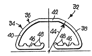
More particular, ~he ~ill structure 24
includes a series of splash bars 32, as shown in
Figs. 1-7. The bars 32 comprise an elongated body
34 having an upper, elongated water impingement
portion 36. As shown, the impingement portion 36
comprises a pair o~ elongated, arcuate in cross-
section side margins 38, 40 and an elongated, flat5
hori20ntal top segment 42 interconnecting the curved
margins 38, 40. The body 34 has an overall height
generally less than one-half of its width, and the
flat top segment 42 has a width in the range of
approximately 15~ to approximately 35~O of the width
of the body 34. In preferred forms of the inven-
tion, the width of the seg~ent 42 is approximately
25% of the width of the body 34.
In one embodiment of the invention, as
viewed best in Figs. 5-7, a preferred overall width
o~ the body 34, as represented by the letter "X" in
Fig. 5, is 1.655 inches. In this preferred form,
the overall height of the body 34, as represented by
the letter "Y", is 0.750 inch, while the width of
the flat top segment 42, as indicated by the letter
"Z", is 0.437 inch. Viewing Fig. 6, each of the
side margins 3~, 40 have a curved cross-sectional
con~iguration with a center of curvature lying Q.0~5
inch beneath the body 34. As illustrated, the
centers of curvature of the side margins 38, 40 are
preferably conicident, and a preferred radius, as
represented by the radius line indicated by the
numeral 44, is 0.844 inch.
q
., :: . .
` ~ '.- ' ' :' ' .
. , - . . ~ ~ . : ,
- .
` "'. : ' ' ' ' ,
1 As sho~l in Figs. 5-7, the hody 34 in-
cludes a normally horizontal bottom wall means
connected to the side margins 38, 40, and the bottom
wall means comprises a pair of substantially flat,
co-planar, spaced walls 46, 46 extending inwardly in
integral relationship from the margins 38, 40.
Also, the walls 46, 46 each include three elongated,
upright, integral ribs 48 for providing strength and
stiffness to the body 34.
The fill structure 24 also includes an
upright grid structure for supporting-the bars 32 in
proper disposition within the tower 20. The grid
structure comprises upright, inclined grid members
50 as well as a series of spaced horizontal grid
members 52.
The splash bars 32 may be supported by the
uprig~t grid structure in a variety of patterns.
Referring to Fig. 2, successful performance is
observed when the bars 32 are supported in a non-
~ staggered relationship by the members SO, 52 on~ 8inch horizontal centers and 4 inch substantially
vertically centers. Good results are also obtained
when th~ splash bars 32 are disposed in the non-
staggered pattern represented in Fig. 3, wherein the
bars 32 are located on 8 inch horizontal centers and
8 inch substantially vertical centers. However, a
preferred disposition of the bars 32 is shown in
Fig. 4, wherein the bars 32 are located in a stag-
gered pattern on 16 inch horizontal centers and 8
inch substantially vertical centers.
Fig. 7 is a representation of the believed
paths of travel for water droplets impacting against
the outer surface of the impingement portion 36.
Droplets hitting the curved side margins 38, 40 are
deflected approximately at an angle equal to their
., : . .. :
.
. . .
- : -. ,
'` : . :
`. `: .
~2~
1 angle of incidence. That is to say, at a point
where the droplets hit either of the curved margins
38, 40, the droplets will be deflected a~ an an~,le
from a perpendicular line drawn through a tangent
line at the impact point, where such an angle is
equal to an angle between the perpendicular line and
the vertical path of the drop before engaging the
impingement portion 36. However, water droplets
impacting the ~lat top segment 42 will rebound, on
the average, at a slight angle in a random pattern,
because a portion of the droplets falling downwardly
functions as deflectors to push the rebounding drops
laterally.
The improved performance of the splash bar
32 is believed to be caused by a balance achieved
between the quantity of water droplets which hit the
flat top segment 42, and the number of droplets
which impac~ against the curved margins 38, 40.
The droplets are uniformly dispersed in the vicinity
surrounding each splash bar 32 such that a more
uniform exposure of the droplets to the cross~lowing
air stream enhances the cooling process. Addition-
ally, most of the droplets engaging the impingement
surface 36 tend to break into smaller drops, thereby
increasing the surface area of the water in contact
with the passing air stream.
Referring to Figs. 12 and 13, the improved
results obtained by use of the splash bar 32 of the
present invention are compared to test results ob-
tained by use of splash bars of different coni~ura-
tion under similar circumstances. Test data from
commonly used rectangular wood boards is indicated
by the numeral 'il" in Fig. 12 (see also ~he column
labeled "1" in Fig. 13), and represents a base line
for comparlng performance of splash bars having
//
. . :
... :
.. ..
- .
-: ~
'-:: , ' . '
'' ~ ` , : ': ' ' ' ' , , :
- . :. :
1 differen~ configurations. The fan motor require-
ments are taken as 200 brake horsepower per fan
regardless of water loading when rectangular boards
are spaced on 4 inch vertical centers and 8 inch
horizontal centers. ~ata obtained from test results
of a half rounded splash bar, having no upper flat
impingement surface, is represented by the numeral
"2", and it can be seen that although performance of
this type of bar is superior to rectangular boards
under high water loadings, such performance falls
off rapidly under lower water loadings. Test re-
sults from use of a half rounded splash bar, having
a relatively wide flat top segment of a width equal
to approximately 45% of the overall width of the
splash bar, is indicated by the curve labeled "3".
As illustrated, the performance of such a splash bar
does not exceed the performance o~ rectan~ular
boards regardless of water loadings. However,
unexpected results were discovered when the splash
bar 32 of the instant invention was tested, wherein
data as represented by the numeral 14- shows super-
ior performance than that obtained by use of rec-
tangular boards, half-rounded bars, or half-rounded
splash bars having a relatively wide flat top seg-
ment. As indicated, the performance of the bar 32,when the width of the top segment 42 is approxi-
mately equal to 25% of the overall width of the body
34, is superior to the results obtained from use of
other tested splash bars regardless of water load-
ings.
Moreover, the test results as enumeratedin Fig. 13 represent conditions wherein the bar 32
is located on 16 inch horizontal centers in rows on
4 inch vertical centers in contrast to the 8 inch
horizontal spacing and 4 inch vertical spacing
. ~
. . .
:
`: ', - ~ . ,
.
1 provided during testing of the rectangular wood
boards. Thus, superior results are obtained even
though half the number of bars are needed, resulting
in a substantial savings of both material and labor.
Moreover, such a reduction in the number of bars 32
within the fill structure 24 ensures that the pres-
sure drop of the passing air s~ream is re~ained at a
minimum. As shown in Fig. 12, the reduction in
operating costs for each fan cell, calculated at
$2,000 per brake horsepower over a 20 year plant
life, in early 1985 U.S. Dollars, ranges from ap-
proximately $7,500 to over $16,000. Obviously, such
a savings is significantly compounded when based
upon a multicell cooling tower having, for instance,
ten fan cells.
Fig. 11 illustrates a retainer 54 which
may be advantageously utilized to secure the bars 32
to the grid members 50, 52. As shown, the retainer
54 has three spaced, depending, flexible tabs 56
which can be deflected laterally to engage the
horizontal grid member 52. The retainer 54 also is
provided with~a flat support 58, the ~mderside of
which rests on the top of the horizontal grid member
52, and the top surface of which engages the bottom
walls 46, 46 of the bar 32. As such, the support 58
isolates the bar 32 from the horizontal member 52 to
reduce frictional wear which might o~herwise occur
due to vibration encountered from operation of the
tower 20. Also, the suppor~ 58 has opposed, out-
wardly extending fingers 60, 60 adapted to engage
opposite sides of adjacent upright grid members 50,
to thereby prevent shiftin~ of the retainer 54 in a
direction parallel to the longitudinal axis of the
bar 32.
/~
,
.
- ' '
'
., ~ .
l The retainer 54 is also provided with an
upstanding arrow shaped bar securing means or clip
~2. The clip 62 may be snapped into place in the
space ~etween the bottom walls 46, 46 in disposition
to engage the inwardmost ribs 4~. In this regard, a
channel between the bottom walls 46, 46 functions
not only to enable attachment of the retainer 54 at
any location along the length of the bar 32, but
also provides material savings and allows the ex-
truder to be operated at a somewhat faster speed.
A second embodiment of the instant inven-
tion is represented by the bar 132 in Figs. 8-10.
In this case, the bar 132 has a body 134 similar to
the body 34 shown in Figs. 5-7, but the bar 132 also
lS includes a pair of outwardly extending elongated
side flanges 133, 133 integrally coupled to thè body
134. The flanges 133 are provided with notches 135
(Fig. 10) of a dimension approximately 0.25 inch
wide and 0.125 inch deep, such that the notches 135
accomodate and grip the upright grid members 15n
(see Fig. 9). The notches 135 are operable to
prevent longitudinal shifting of the bar 132 during
tower operation.
In other respects, the configuration of
the bar 132 is substantialIy similar to the bar 32.
. That is,- the body 134 has elon~ated, curved side
margins 138, 140 along with a flat, elongated top
segment 142 interconnecting the margins 138, 140.
The body 134 also includes inwardly extending flat,
spaced bottom walls 146, 146 having ribs 143.
Referring to Fig. 8, the preferred overall width o~
the bar 132, which includes the width of the body
134 (1.655") pIus the width of both side flanges
133, 133 (0.415") is represented by the letter "X"
and is equal to 2.070 inches. The overall height of
/~
, . - ' ~ . ' '~: ' ' ' , .
. .. . . - .
-: .... : , . .. . . .
- . ., - . .- ~ . ~ . . :. . . .
.-. .: : .
, . ~ . . -, . . .
- . : : . " : ., '
~27Çi1~
the body 134 is indicated by the letter "Y", and
preferably is 0.75n inch, while the width of the
flat top segment 134, as represented by the letter
"Z", is preferably 0.437 inch. Moreover, the cen-
ters of curvature of the side margins 138, 140 are
coincident and lie 0.06~ inch beneath the body 134,
and the radius of each curve is 0.844 inch.
Fig. 9 is a believed representation of
hypothetical deflection of water droplets impinging
upon the bar 132. As noted, the deflection is
similar to the water dispersal pattern obtained by
use of the splash bar 32 in Fig. 7, with additional
water deflection occuring on the upper surfaces of
the side flanges 133, 133 as shown. As a result,
the uniform water deflection pattern obtained from
use of the bar 132 is believed to provide superior
performance, in similar manner to the results ob-
tained from use of the bar 32.
/S
~5
.
:
:
.. .. ~ .
': : - " ' ; : `
.
' : ` `, . : . . , :
- - . . ,
.