Note: Descriptions are shown in the official language in which they were submitted.
~276264
SYSTEM FOR NAVIGATING A FREE RANGING VEHICLE
BACKGROUND OF THE INVENTION
The invention relates to a system for navigating
a free ranging vehicle, provided with steering- and control
means on a surface over which this vehicle is to drive,
comprising means for detecting the position of the vehicle
on the surface and means to determine and/or correct the
path to be followed by a vehicle between an arbitrary
starting point and an arbitrary destination.
The prohlems relating to navigation of a free ranging
vehicle are described in the article: "Free Range AGV
Uses Laser Guidance", published in FMS Magazine, ~uly
1983. The solution given in this article: the use of a
number of coded beacons which are scanned by a laserbeam
is not without problems: the processing of the various
signals is very complicated, an acceptable accuracy is
difficult to obtain and it is clear that this system can
only be used on surfaces on which there are no obstructions
of some height.
The invention aims to provide a system by means of
which can be navigated with an accuracy which is sufficient
for practical purposes, which does not call for far-reaching
modifications of the surface on which the vehicles run
~276264
and which is in its operation so flexible that practically
each surface can be adapted to be used with the system
according to the invention, and with which navigation
can be effected between any arbitrary starting point and
destination. In this connection it is observed that by
navigation is meant in this context the process of deter-
mining a suitable path for travel hetween a known starting
position and an arbitrary destination, and the process
of verification and correction of the path that is actually
followed towards the planned path.
SUMMARY OF THE INVENTION
According to the invention this aim is obtained in
that the surface carries a grid of passive marker elements
and the vehicle is provided with detectors for detecting5 same.
By using a grid on, or embedded in, the floor the
measurement problem normally associated with free-ranging
and navigation of driverless vehicles is largely eliminated.
The small distance between detector(s) and objects
(marker elements) eliminates the measurement problems
encountered with the known navigating systems.
Navigation on a grid consists of
1) computing a path over the grid so that the vehicle
knows when to expect to travel over which particular
grid element, and of
2) interpreting the detection of grid elements during
route-execution so that the path is effectively followed
and can be adjusted towards the planned path.
In other words: the vehicle will always know what to expect.
As a result, markers that are identified with an explicit
code, as for example radio beacons, are not necessary.
This fact greatly simplifies the physical form of the
~276264
grid that is to be installed on the floor.
The progress along the pre-computed path (computed
directly after receiving a destination) is frequently
checked when passing over markers and, if necessary, the
actual path is adjusted. Between markers the vehicle cannot
"measure" its position, but the measurement of travelled
distance allows a sufficiently accurate prediction of
the actual position at any time. Measured quantities can
be the displacement of a marker relative to the longitudinal
axis of the vehicle or angles at which line-shaped markers
are crossed.
of course such a system as described must have suf-
ficient on-board computing power.
The big advantages of the system according to the
invention lie in its great flexibility, the possibility
of immediate adaptation to changing circumstances, the
fact that passive marker elements are inexpensive and
particularly that the vehicles are completely independent
of the surroundings in which they must move. The routing
is flexible, and can be determined anew by the computer
at the beginning of each path while with the present state
of the art suitable detectors are available.
It is observed that the British Patent Specification
1.150.029 describes a system for guiding a vehicle provided
with its own driving motor, based upon the use of an active
network of electrical conductors carrying an alternating
current, the vehicle following the path of the wires by
sensing the electromagnetic field around the conductor.
The vehicle to be guided starts by following a certain
conductor and counts the number of transverse conductors
which has been passed by it; after a predetermined number
~Z76Z64
-- 4 --
of these conductors have been passed a left- or right-hand
turn can be initiated, and so on.
The number of starting points and destinations and
the path to be followed are thus limited; the necessity to
bury the insulated conductors (which necessarily may not be
interrupted) in the ground, makes this known system in fact
only suitable for agricultural applications - such as
described in said patent specification - where the above-
mentioned disadvantages can be tolerated.
Preferred embodiments are described in the subclaims
in connection with which it is observed that particular
advantages are obtained when the marker elements consist of
discrete elements, arranged according to an essentially
regular pattern and particularly of transponders which are
activated by irradiation with electromagnetic energy. Such
transponders, as known, are commercially available and have
the advantage that they can emit coded information in response
to the irradiation and thus serve to facilitate the
navigation.
The marker elements may also consist of magnetically
conducting material or permanent magnets, with the advantage
that by means of a suitable orientation thereof additional
information can be supplied to the vehicle. However, the
discrete marker elements can also be of the type which can be
sensed optically.
An embodiment of the invention is, therefore, a
system for navigating a free ranging vehicle, provided with
steering and control apparatus on a surface over which the
vehicle is to drive, comprising apparatus for detecting the
position of the vehicle on the surface and apparatus to
determine and/or correct the path to be followed by the
vehicle between an arbitrary starting point and an arbitrary
destination, in which the surface carries a grid of passive
~Z76264
- 4a -
marker elements and the vehicle is provided with detectors for
detecting the passive marker elements.
S Another embodiment of the invention is a method of
navigating a free ranging vehicle, provided with computing
ability for storing information about the route to be
followed, using the system described above, comprising the
steps of starting from a known starting point, determining the
angle at which in a first interception point the first marker
element is intercepted by measuring the path or paths covered
by the vehicle between the moment at which two respective
detectors on the vehicle with a known mutual distance passed
the marker, and measuring the path travelled by the vehicle
between the starting point and the first interception point.
The position of the first interception point is determined
from the above data. The actual position data is compared
with the nominal position data stored in the computer. If
necessary, the path to be followed by the vehicle from the
first interception point to the next interception point of
which the nominal position data is stored in the computer is
corrected. The above procedure is repeated for the subsequent
interception points.
Another embodiment of the invention is a method of
navigating a free ranging vehicle, provided with computing
ability for storing information about the route to be
followed, using the system described above, comprising the
6teps of starting from a known starting point, determining at
the passing of the first discrete marker element the distance
thereof with respect to a reference point on the vehicle,
together with the distance travelled by the vehicle, and
comparing the actual data with the relative nominal data
stored in the computer of the vehicle. If necessary, the path
to be followed by the vehicle from the first interception
35 ~point to the next interception point, of which the nominal
position data with respect to the nominal data to be followed
.
1276264
- 4b -
is stored in the computer, is corrected. When passing the
next interception point, the distance to the reference point
S on the vehicle is compared to the distance travelled by the
vehicle when moving from the first interception point to the
second interception point. The above-described comparing and
correcting step is repeated, and the above procedure for
subsequent reception points is repeated.
10 SURVEY OF THE DRAWINGS
Fig. 1 is a schematic view of a surface provided
with a grid of line-shaped markers and elucidates the
navigation on such a grid;
Fig. 2 is a top view of a s~rface provided with a
grid of discrete markers and elucidates the navigation on
such a grid.
~276264
-- 5 --
Figs. 3a, 3b and 3c relate to the navigation on parts
of a surface provided with line-shaped markers;
Fig. 3d elucidates another way of navigating, using
a grid of discrete markers, if necessary combined with
odometry;
Fig. 4a is an upper view of a part of a line-shaped
marker;
Fig. 4b is a section over the line IVa-IVa in fig.
4a;
Fig. 5a is a top view of a part of a grid made from
Stelcon( ) plates;
Fig. 5b is a cross section over the line Vb-Vb in
fig. 5a;
Fig. 6a is a schematic top view of a vehicle provided
with a number of detectors;
Fig. 6b is a schematic top view of part of a modified
vehicle according to the invention to be used with discrete
markers;
Fig. 7 shows the use of a discrete marker of the
transponder-type in combination with a suitably equipped
vehicle.
DESCRIPTION OF THE PREFERRED EMBODIMENTS
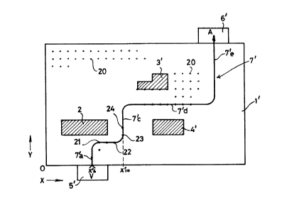
Fig. 1 shows an example in which the vehicle, provided
with a very simple navigating system, can range over a
surface from a starting point to its destination, by fol-
lowing a path which consists of essentially straight parts
which are interconnected by standard turms. This path
is determined by line-shaped marker elements. Fig. 1 shows
a surface, indicated generally with reference numeral
1, and provided with a grid of line-shaped markers which
are arranged according to an orthogonal coordinate system
with origin 0; the marker lines are indicated with res-
pectively xl, x2,... and yl, y2,...
Each square on the surface 1 is thus defined by an
X- and Y-coordinate and the complete track of a vehicle
over the surface 1 is in this simple example of navigating
obtained by covering track parts in the X and Y direction
respectively. Other track parts at an angle with these
directions are also possible, as will be described later
on.
~276264
-- 6 --
Fig. 1 shows three hatched surface parts indicated
with respectively 2, 3 and 4. These are surface parts
which cannot be covered by a vehicle, for instance because
they are used for storing materials. A vehicle which leaves
from the point of departure 5 and has as its destination
the point of arrival 6 could follow a route such as in-
dicated with the line 7; this route comprises a succession
of straight line elements, starting with a part 7a in
the Y-direction, thereafter a part 7b in X-direction,
followed by a part 7c in Y-direction, a part 7d in X-direc-
tion and once again a part 7e in the Y-direction. In which
way the drive- and control mechanism of the vehicle will
receive the various necessary commands will be explained
later, but from the above it will be clear that the route
as covered is in fact determined by continuously determining
the position of the vehicle with respect to the marker
elements of which the position is known and by counting
the number of passed markers.
Fig. 2 shows a surface which is in principle the
same; corresponding parts are here indicated with the
same reference numerals as used in fig. 1 but provided
with an accent mark. In this embodiment the markers consist
of discrete marker elements 20 provided on the crossing
points of the X- and Y-lines of an orthogonal coordinate
system. While a vehicle which is guided by means of line-
shaped marker elements can use a relatively simple set
of detectors for example proximity switches to follow
these marker elements a vehicle which is used in combination
with the discrete marker elements according to fig. 2
must be provided with a more elaborate control system
which is able to follow, starting from a certain known
starting point, a predetermined track to the next discrete
marker element and which is capable to execute turns to
the right and to the left with a standard radius. The
counting-off of the marker elements is effected in principle
in the same
~2~7626A
,
way as in the embodiment according to fig. l.
A vehicle which leaves at point x'6 must thus after
the passing of two markers, initiate a right hand turn
which brings it above the marker 21 at the crossing point
of - imaginary - coordinate line x'7 and y'3 and then
go straight on; after passing the second next marker 22
a left hand turn must be initiated which brings it above
the marker 23 at the crossing point of the - imaginary
- line x'10 and y'4 whereafter it goes straight on to
the marker 24, etc. A specific embodiment of such a discrete
marker will be described later on.
Fig. 3a elucidates the way in which navigation is
possible over a grid of line-shaped marker elements when
traversing an arbitrary route across the surface, from
a first position to a second position.
Firstly it must be pointed out that navigation ac-
cording to this example presupposes that the route to
be followed consists of moving from one, known, point
to the next point and determining the position of this
next point. In fig. 3a it is presumed that the vehicle
starts at Pl of which the position is known and must move
to P2, from P2 to P3, from P3 to P4 and so on. Fig. 3b
elucidates this and relates to the route part between
P3 and P4.
At the moment tl (vide fig. 3b) the right hand detector
22a of the schematically shown vehicle 21 passes the vertical
line-shaped marker 25 (Xl) and at moment t2 the left hand
detector 22b passes this vertical marker 25. By using
odometry - for instance employing rotary encoders coupled
to the rear wheels, combined with digital counters the
paths, covered by the detectors 22a and 22b in the direction
of the route 26 can be measured. As the distance d between
the detecting elements 22a, 22b is known the value of
~27626A
-- 8 --
angle ~ is known from tg~ = - and from ~ follows, as
~ = (90 ~ 51
and d being known.
The exact position P4' at which detector 22b causes
the horizontal marker element can be computed when 52
(distance between crossing point of vertical marker P3'
and crossing point horizontal marker) is measured as OP4'
= 52 sin ~
In the same way, P5 (fig. 3a) can be determined star-
ting from the now known position P4. The fact that ateach crossing point of a line-shaped marker the angle
between the actual track and said marker is known, results,
combined with information about the position of the pre-
ceding crossing point into information of the actual cross-
ing point of said marker. It must be born in mind thatthe nominal positions of the points Pl, P2, etc. are com-
puted and stored in advance in the central computer of
the vehicle. Py comparing the position of the actual cross-
ing points with the pre-computed data steering corrections
can be made when the vehicle deviates from its planned
route.
Of course it is advantageous when the vehicle is
also capable of negotiating turns which interconnect one
track part with another. Fig. 3c relates to this situation.
In fig. 3c is assumed that the vehicle makes a turn with
a known radius R and travels with a constant speed v.
Here, too, the vehicle 21 is provided with two detectors
22a, 22b at a distance d.
It follows from fig. 3c that the detector 22b will
be the first one to cross the horizontal line-shaped element
23 at the moment tl and at this moment detector 22b emits
a signal to a central control- and computing unit (to
be described later). When a few moments later detector 22a
~276264
crosses the horizontal marker element 23 at moment t2
it also emits a signal; upon reaching the vertical marker
element 24 the right hand detector 22a will be the first
on to emit a signal at moment t3 and thereafter the left
S hand detector 22b will emit a signal at moment t4.
It can be shown that the following equations are
valid:
tg ~ = vd (t2 - tl) (1)
tg ~ = v(t4-t3) (2)
R(~ - ~ ) = v(t3 - t2) (3)
From these equations ~X , ~ and R can be determined. It
then follows:
OA = R(cos ~ - cos~ ) (4)
OB = R(sin~ - sin ~ ) (5)
Thus by measuring the time only between the moments
on which the detectors 22a and 22b cross the horizontal
marker element 23 and the vertical marker element 24 res-
pectively the exact position of the vehicle with respect
to these marker elements and the route which it has been
following is known.
Another solution would be the use of odometry (meas-
uring the distance travelled by two wheels of the vehicle,
said wheels being at a known distance d) in combination
with the measurement as described before of the angle
at which the vehicle crosses a certain marker element;
then the angle at which the next marker element is expected
to be crossed can be computed.
~276264
-- 10 --
The nominal crossing angle is known and on the basis
of the difference between the actual crossing angle and
the nominal crossing angle, the position error can be
computed and the path of the vehicle corrected.
Of course combining time measurement with odometry
will result into an even more foolproof navigation.
Fig. 3d shows an example of navigating using a grid
of discrete marker elements. The vehicle 21 with its lon-
gitudinal axis 21a is provided with two linear arrays
of detectors 27a, 27b respectively to the right and to
the left of the longitudinal axis 21a and perpendicular
thereto. In fig. 3d it is presumed that the path 28 to
be followed is in line with the longitudinal axis 21a
of the vehicle and that this path does not coincide with
the coordinate system according to which the markers 20
are arranged.
At the moment tl the left hand array 27b - after
having travelled a known distance sO from a known starting
point - detects the marker 20a at a distance ~1 to the
left of the axis 21a. Then follows the sequence:
After distance sl array 27a detects marker 20b at ~2 to
the right -
After s2 array 27a detects marker 20c at ~3 to the right -
After s3 array 27b detects marker 20d at ~4 to the left -
25 After s4 array 27b detects marker 20e at ~5 to the right -
After s5 array 27b detects marker 20f at ~6 to the right -
and so on.
Thus when the respective detected lateral distances
of the successive marker elements with respect to the
longitudinal axis 21a correspond with the data as stored
in the navigating computer of the vehicle, the vehicle
"knows" that it is following the correct track; if not
so corrections can be made. Note that detecting the
travelled distances sO,
~2~62~i4
-- 11 --
sl, etc. is not really necessary but results as said above
into an advantageous redundancy.
Line-shaped markers are possible in various em-
bodiments. They can, as known, consist of light-reflecting
material and be painted in each desired configuration
on the surface.
Scanning of such lines with optical sensors is known
but such markers have to drawback that they get dirty;
preferably one will use markers which consist of mag-
netically conducting material. They can be embedded inthe floor such as shown in the figs. 4a and 4b. Reference
numeral 30 indicates the floor; the line-shaped marker
31 is embedded a short distance under the surface.
Many advantages are obtained when the grid consists
of the metal frames of the well-known concrete floor
elements best known under the trademark "Stelcon"(R).
Figs. 5a and 5b show a number of such plates of which
some are indicated with 32a - 32c. Each plate has, as
known, a metal frame of which a number are indicated with
33a - 33c and which, as shown, in combination constitute
a perfect grid of mutually perpendicular lines 34a -
34d and 35a - 35d respectively. Such a grid of marker
elements is eminently suitable for use in the system
according to the invention.
Fig. 6a shows a vehicle with detectors and control
means for navigating across a surface with line-shaped
marker elements. The vehicle 40 comprises front wheels
41a, 41b, a steering unit 42, rear wheels 43a, 43b driven
by the motor 44 and is surrounded by a safety fender 45.
The central control unit 46 receives signals from detectors
47a, 47b placed at the front of the vehicle and responding
to the presence of marker elements.
Detectors 49a, 49b at the respective sides of the
longitudinal
~276264
axis 49 can be used in a simple navigating system to follow
a longitudinal marker element. The central unit 46 receives
commands from the program- and control unit 47 via the
connection 48; the unit 37 can be provided with a keyboard
49' to input data and information about the track to be
followed but such information can also be transmitted
wirelessly by means of a receiver 50 and from a distant
control unit 51 with an emitter 52 and keyboard 53.
The control unit 46 controls via the two-way connection
45 the steering device 42 and receives back steering angle
information; the drive unit 44 is controlled via the connection
55.
Of course it is also possible that all information
supplied by the sensors is fed back to the unit 47 as
indicated schematically with the dot-lined connection
57, is then emitted to the central unit 51 and processed
there. The unit 51 then returns the necessary steering
commands to the vehicle. The abovementioned control- and
navigation system can be completed by a device to determine
the distance covered (odometry) in the direction of the
track, for using instance encoders 58a, 58b, coupled to
the rear wheels of the vehicle and cooperating with a
revolution counter 59 which feeds this information to
the control unit 46.
Fig. 6b shows the front part of a vehicle to be used
for naviga'ing over a surface provided with a regular grid
of discrete marker elements, such as the surface s~own
in fig. 2, and in the way as described hereinbefore with
reference to fig. 3d. The vehicle 40 is provided at its
front end with two lineair arrays of detecting elements
60a,-60b. These arrays are scanned under the control of
the central unit 64 and they feed back their information
~2~76264
- 13 -
to this central unit as indicated schematically by the
connections 61a and 61b. The other parts of the vehicle
are not shown and they are the same as those shown in
fig. 6a. The detectors can be known proximity switches.
Fig. 7 relates to the use of marker elements of the
so-called "transponder"-type. Such elements are marketed
by the Dutch firm of Nedap, Groenlo, and have the shape
of a small cylinder, about 8 cm long and with a diameter
of about 4 cm. They have the property that when they are
excitated by irradiation with electromagnetic energy with
a frequency of about 100 kHz, they respond by emitting
a coded signal at the same frequency. This makes it possible
to use them not only as marker element, but also to transmit
to the vehicle explicit information about its actual
position on the grid which can be very useful.
According to fig. 7 the schematically shown vehicle
110 has a front wheel 111 with its driving motor 112,
rear wheels 113 and 114, each with an odometry encoder
113a and 114a respectively, an emitting loop 115, excited
by the emitter 116 and, in this example, five receiver
loops 117a. . 117e of which the outputs are connected
to the circuit 118. This circuit 118 decodes the information
present in the signals picked-up by the receiver loops
117a..117e, and emitted by a marker 119 which is in the
vicinity of the vehicle 110 and close enough to the emitter
loop 115 to be excited thereby. Another marker element,
too far away to be detected in the shown position of the
vehicle, is indicated with ll9a.
Note that the position of the marker 119 with respect
to the longitudinal axis llOa of the vehicle 110 can be
derived from the relative strenghs of the signals produced
by the loops 117a..117d.
~276Z~4
- 14 -
After the evaluation of the received signals, the
decoder/level-detector 118 transmits the position in-
formation to the central computer 120.
Of course the discrete marker element can also consist
S of marker elements which can be scanned optically, for
instance by having light reflecting surfaces or optically
recognisable shapes. Examples of these elements are
described in for instance, the German Patent Application
2.910.490, relating to a vehicle guidance system.
It is clear that within the framework of the invention
many other embodiments are possible; a practical and working
embodiment of the system according to the invention can
be constructed by any expert using the present-day systems
and components known to him. Particularly in connection
with the logistics of free ranging unmanned vehicle systems
one can make use of excisting technology and this is also
valid with regard to the detectors which are necessary
to sense the marker elements and the circuits for processing
the signals resulting from the sensing.