Note: Descriptions are shown in the official language in which they were submitted.
~Z7~
FIELD OF INVENTION
The field of the present invention relates
generally to vapor recovery systems, and more specifi-
caIly to fuel dispensing systems including a venturi
aspirator for removing accumulated fuel from the vapor
path of vapor recovery hoses included in such systems
between the nozzle and meter housing.
In fluid distribution systems, such as
gasoline pumping systems for delivering gasoline to the
lo fuel tank of the vehicle, environmental protection laws
require that vapors emitted during the fuel dispensing
process be recovered. One such vapor recovery system
includes a vapor recovery hose surrounding a product
hose for delivering fuel to a nozzle, typically the
nozzle of a gasoline pump. Vapors collected from the
vehicle tank at the nozzle end are pushed by positive
pressure which develops within the vehicle tank, nor-
mally called a balanced system, or sucked by a vacuum,
from the nozzle back into the gasoline storage tank of
the product distribution system via the vapor return
path provided by the space between the coaxial product
and vapor recovery hoses. At times liquid fuel may
overflow from the nozzle into the vapor recovery path
of the vapor recovery hose and collect at a low point
in the vapor recovery hose causing partial or total
blockage of the return path for the vapors. Even
partial blockage of the vapor recovery path of the
vapor hose must be avoided in order to insure the
product or fuel distribution system meets the environ-
mental protection requirements imposed by local, state,and federal governments.
L ',
` . ~
,
7~
~ s will hereinafter be explained in more detail, U.S.
Patent No. ~,566,504, assigned to the assignee of the present
invention, one embodiment shows one end of a flexible hose
inserted into a vapor recovery hose in an area where liquid ~uel
may accumulatev and the other end of the hose connected to a pump,
for pumping the fuel out of the vapor recovery hose to maintain a
clear vapor path.
This patent teaches that during refueling of an
automobile, a liquid suction pump is energized to suck away any
liquid fuel entrapped in an outer coaxial vapor recovecy line via
a flexible hose. The unwanted fuel is discharged via an outlet
port into the lower portion of a vapor recovery line within the
gasoline dispenser housing, for return to an underground storage
tank, in that example.
In U.S. Patent No. ~,863,687, for "Return of Vapor
Condensate Formed in Dispensing Vaporous Liquid", issued February
4, 1975, the invention disclosed includes a reservoir for
collecting condensate from vapors that are flowing through a vapor
return line of a fuel delivery system. The product delivery hose
and vapor return line are separate and individual. The reservoir
is located within the gasoline dispenser housing of the system,
remote from the product delivery hose and vapor return line.
Condensation that forms in a portion of a substantially overhead
vapor return line partly returns to a reservoir, from which it is
returned to the product delivery hose via a product operated pump
also located wihtin the dispenser housing adjacent to the
reservoir. In one embodiment, a venturi pump is used to suck
condensate from the reservoir into the product delivery line
portion located within the meter housing. However, no teaching or
suggestion of any apparatus or method for maintaining the vapor
return line ho6e free of liquid fuel is made or even alluded to.
The present invention includes venturi pump means located
within the fuel flow path of a product hose for pumping out or
aspirating liquid fuel that may accumulate in the vapor pa~h of a
vapor recovery hose that is either separate from or coaxial with
and surrounding the product hose. and returning thi~ fuel to
.~
7~7
the ~uel Elowing in the pcoduct hose, or maintaining
the vapor path of the vapor hose clear ~or vapor flow
between a nozzle and the metering housing.
~ n the ~igures, wherein like items are
indicated by the same reference number:
Figure 1 is a partial cutaway view of a
nozzle and coaxial hose assembly incorporating one
embodiment of the invention;
Figure 2 is a detailed cutaway view of an
embodiment o~ the invention;
Figure 3A is a top view of a venturi pump
body of a preferred embodiment of the invention;
Figure 3B is a sectional view along AA of
Figure 3~;
Figure 3C is an end view taken from the
right of the venturi pump body of Figure 3a;
Figure 4A is a cross-sectional view o f a
check valve and filter assembly of the preferred
embodiment of the invention;
Figure 4B is an end view ta~en from the
right o'f the check valve and filter assembly of Figure
4A;
765~7
Figure 5A is a side view with paetial
cutaway of the venturi pump assembly o the pre~erred
embodiment of the invention;
Figure 5~ is an end view rom the r;ght of
the venturi assembly of Figure 5~;
Figure 6 is a partial cutaway and exploded
assembly view o the preferred embodiment of the
invention;
~ igure 7 shows one application of the
present invention in a multiple product dispenser
system; and
~ igure 8 shows an alternative embodiment of
the invention.
With reference to figure 1, the invention
generally includes a venturi liquid removal system 20
incorporated within hose 7 of the coaxial hoses S~ 7
and nozzle 3 assembly o~ a fuel distribution system.
flexible tubing 22 is connected to the venturi pump or
aspirator assembly 20, with the free end o the tubing
2~ 22 being located in an area of the vapor recovery hose
S where liquid such as gasoline is expected to accumu-
late due to flowback rom the no'zzle 3 during the
dispensing of fuel to a vehicle 1. When fuel flows
through the product hose 7, for delivery through the .':-
nozzle 3 to a vehicle 1, the venturi pump assembly.20 '~
: is operative by the flow of fuel to cause~-liquid
accumu,lated in the vicinity of the free end of:tubing '-;
22 to be sucked~back or aspirated through the tubing '.~
and into the fuel ~lowing from the venturi,assembly':'20: . :
into thè nozzle 3. In this way, the vapor`path~o~ thé'~
vapor hose S is maintained substantially clear o
~ .
~7~7
blockage by ~uel that may overflow or "spitback" ~om
the nozzle 3 into the vapoc path, thereby permitting
the ~ree ~low of vapors ~rom the nozzle 3 back through
the vapor path o~ vapor hose 5 to a collection point.
One embodiment o~ the inventLon is showr. in
~igure 2, and includes a venturi assembly 20 mounted
between the inlet end 24 of a nozzle 3 and the product
delivery end 26 of a coaxial hose system, including an
inner product delivery hose 7 surrounded by an outer
vapor hose 5. As shown in this example, the venturi
assembly 20 includes an outer tubular member 21 fabri-
cated from a rigid material, such as appropriate
metals, having threaded end portions 28 or connection
to mating members o the noz~le 3 and vapor hose con-
nection 6 as shown. The venturi pump or aspirator 31
includes a rigid tubular housing 32 shaped as shown
or enclosing a sprinq loaded poppet valve 34. The
poppet valve 34 has a centrally located rod-like member
36 ideally mounted within a tubular sleeve member 38,
and a spring 40 for providing appropriate spring
biasing of the poppet valve 34. ~ rigid inlet tube 42
is provided or connecting the inlet hole 44 to the
flexible hose or tubing 22, the latter which can be
~abricated from polyethylene or butyl rubber, for
example. A flapper valve 46 serving as a check valve
is preferably installed within the inlet tubing 42, for
preventing gasoline or other liquid fuel peoduct
fiowing through the product hose~7 from betng forced
into the vapor path of the vapor hose 5.~ In other
, . . . .
words, the flapper valve 46 serves to insure that fluid -
can only flow in one direction, namely from tbe`~vapor
path-of vapor hose 5 to the ventur~ pump 31. A;sui~
able check valve 46 is believed to be a duck:bill chèck~
valve manufactured by Vernay Laboratories, Inc.~yellow ~-
Springs, Ohio, 45387, under Vernay Part No~ V~3426.
~2~6~7
~lso installed in the inlet tubing 42 is a filter
screen 48 serving to ~ilter out any contamination con-
tained within the ~uel sucked back to the venturi pump
31 via the tubing 22. The filter substantially ensures
reliable long-term operation o check valve 46. Ring-
like bushing members or spacers 50 are provided for
maintaining the venturi housing 31 centered within the
venturi assembly ?0, as shown. The rings or bushings
50 include a plurality of holes or openings 52 for
lo permitting the free flow of vapors from a nozzle 3 to
the vapor hose 5 as shown. The flexible tubing 22 is
passed through one of the holes in the ring or bushing
member 50 associated therewith. The product hose 7 for
carrying fuel to nozzle 3 is connected to the inlet S4
of venturi 31 via 0-ring seals 56, whereby the inlet 54
receives rigid hose connector 8. Similarly, the pro-
duct outlet portion 58 of venturi housing 31 is coupled
to the product inlet 60 of nozzle 3 via 0-ring seals
62.
With reference to ~igure 2, when the fuel
distribution system is operating to pump product
through the product hose 7 in the direction of the
arrows, the venturi pump or aspirator 31 is operative
to draw fluid from areas within the vapor hose 5 where
the fluid may accumulate (see Figure.l?,'through the
inlet tube 42 and hole 44 for return to the:product
stream flowing through the product hose 7,,.as-shown. ,~
The spring loaded poppet valve 34 permits,the~.venturi~
pump to draw~fluid even at relàtivély low';flow ratès~of'.''
product.. As will be shown, unlëss it is nëce'ssary to ~
produce adequate suction via the venturi: p:amp,31 ,,.'~
throughout a very wide range of product fl'ow rate,~.~....
including very low flow rates of product,,the~sprinq`;;~
loaded poppet valve 34 may not be required.
'7
~s shown, in operation of the embod~ment of
the invention of Figure 2, product ~ccumulation in the
vapor hose 5 is removed automatically during normal
fueling of a vehicle, thereby preventing excessive back
pressure on the balanced vapor recovery nozzle 3
because o~ such pcoduct accumulation. Accordingly,
vapor leakage at the nozzle-~iller neck ~not shown)
between the vehicle 1 gasoline tank and outlet o~
nozzle 3 is substantially eliminated. Note that the
lo venturi pump 31 can be located at any point down stream
of the meter housing 11.
When the spring loaded poppet' 34 is imple-
mented, the poppet 34 is always located as shown for
opposing the direction o~ product flow through the
product hose 7 o~ the coaxial hose system 5, 7. Con-
trolled loading by the spring 40 produces a small cross
sectional flow area and consequent high velocity of
product past the inlet hole 44. The high velocity
product flow produces a low static pressure on the
inlet tube 42, thereby providing the suction for
aspirating accumulated product out of the vapor hose 5.
The one way check valve 46, as previously mentioned,
prevents product rom being pumped into the vapor path
portion oE the vapor hose 5 when the fuel is not
flowing or the flow rate is low. Note also, that the
venturi pump 31 can be located within the nozzle
assembly 3, in certain applications. The suction tube '~
22 would then be routed back-from the nozzle 3 to the
best position for removing accumulated product from the.~ ;~
vapor path o~ the vapor hose 5.'. ~lso,.the venturi pump~
31, in this example, could be placed between.the nozzle '.;
valve housing- and filler tube~'ln ~he'vapor~recovery
nozzle (not shown3. The advantage of th~s latter~ :' .':
cA -
3L27~7
approach is that at low ~low conditions, no pressure
would be applied to the poppet valve 34 or tube ori~ice
44, whereby the check valve ~6 could be eliminated.
A second and preerred embodiment o~ the
invention is shown in Figures 3A through ~igure 6. In
Figure 3A, a top view of the housing of the venturi
pump 64 ultimately developed ~or use in product by the
inventors is shown.
In Figure 3B, a sectional view taken along
~o AA of Figure 3A is shown. Note that in this embodiment
of the invention no poppet valve is utili~ed, accord-
ingly the venturi pump 64 is o~ a fixed throat design,
in contrast to the variable throat design of Figure 2
provided by the poppet valve 34. The dimensioning of
the venturi chamber of the venturi oump 64 is con-
sidered critical to obtaining a low static pressure at
the ori~ice 66 sufficient for continuously aspirating
or sucking fluid out o~ the vapor hose 5 (for example~
over a given range of ~low rate o~ product. The
present inventors designed the venturi pump 64 to pro-
vide low enough static pressure for adequate aspiration
away from the vapor path of the vapor hose 5 over a
product flow rate range of 6.5 to above 10.0 gallons
per minute of gasoline, in this example. Certain criti-
cal dimensions (Dl, D2, D3, Ll, L2, L3, a , and ~ ) for ~-
the venturi pump 64 to provide such operation are dis~
cussed in the following paragraph.
The,venturi pump 64 includes as showo in,~
Figure 3~, an inwardly tapering conical inlet throat 68'~
relative~to,the direction of fuel flow having an entry~
diameter Dl of O.S3 inch, an exit diameter D2 of 0.213~
inch, an angle of 12 degrees lS minutes with its'''
longitudinal axis 70 measured from its exit end, and a
- 9
length Ll with respect to its longitudinal axis 70 of
0.720 inch, a centcal cylindrical portion 72 having a
length of 0.10 inch, and a diametec equlvalent to the
exit diameter D2 of the inlet throat 68. The inlet
port 66 for the venturi pump 64 includes a hole through
the wall of the cylindrical portion 72, having a 0.062
inch diameter. The venturi pump 64 ~urther includes an
outwardly tapering conical outlet throat 74 having an
entry diameter equivalent ~o the diameter of cylin-
drical portion 72 or the exit diameter D2 of the inlet
throat 68, an exit diameter D3 o~ 0.50 inch, a length
L3 with respect to its longitudinal axis 70 of 2.07
inches, and an angle B o~ 4 degrees with its longi-
tudinal axis 70 measured from its entry end adjacent
cylindrical portion 72. The reduced portions o~ the
body of the venturi pump 64 associated with the outlet
throat 74 includes sections 76 and 78 having diameters
of D4, and Ds, respectively, which are dimensioned for
connection or coupling to a particular nozzle or hose
assembLy. Obviously, the overall outer configuration
and dimensioning of the venturi pump 64 may be tailored
to or adapted for the particular mounting con~iguration
and application. Also in this example, preceding the
inlet throat 68 is a coupling section 80 configured ~or
coupling to a coaxial hose assembly 82 as shown in
Eigure 6, in this example. The coupling section 80
includes two raceways 84 and 86 ~or receiving "O" rings
88 as shown in Figure '5~A. A chamfer 91 is included at
the entry of the-coup~ing chamber 80 portion of venturi
pump 64., Also, a stud like projecting portion 90 is
included in the:.venturi pump 64 housing, and.has a hole
92 for receiving. a groove pin 94, as shown in Eigure.
5A, whereln the groove pin 94 is pressed into the hole -
92. Another stud like projecting portion 96 is-
included in the housing configuration for venturi pump
64, having a hole 98 partially through this portion 96
~3
~276~
-- 10 --
and intersecting the inlet hole 66, as shown. A
cham~er 100 is included at the entry to the hole 98.
~ole 98 provides the inlet port ~or venturi pump 64. In
Figure 3C an end view of the venturi pump 64 taken rom
the inlet throat 68 is shown.
With further eegard to the example o~ the
pre~erred embodiment of the invention, a check valve
and filter assembly 102 is provided as shown in Figure
5A. The check valve 104 is identical to the check or
flapper valve 46 o Figure 2, in this example, and as
previously mentioned is manufactured by Vernay Labora-
tories, Inc., Yellow Springs, Ohio, US~ under Vernay
Part No. VA3426. A cap like ~ilter screen 106 is also
included for serving the same function as filter 48 of
~igure 2. The outlet end 108 is coupled to the inlet
hole or port 98 of venturi pump 64. The other end 110
is configured eor coupling to a flexible tube 112, as~
shown in Figure 6. An end view of the filter assembly
102 taken from the end 110 is shown in Figure 4B.
rn ~igure 5A, the venturi pump 64 is shown
in its assembled configuration with check valve and
filter assembly 102, and including "O~-rings 88, and
groove pin 94. An end view of the assembly taken from
the inlet 68 end is shown in Figure 5B.
In Figure 6, a partially exploded, partially
cutaway assembly view is shown of one application of
the subject invention. The flexible product return
tubing 112 is clamped to the check valve and ilter
assembly 102 via a tubing clamp 114. The other end o~
the product return tubing 112 is clamped via another
tubing clamp 114 to a suction head 116 as shown. Clamps
118 are used eor securing the product return tubing 112
and suction head 116 to the product hose 120, ~or
~'
.,
. ~
~ ~'7~7
example. Outer vapor hose 122 surrounds the product
hose 120, to form a coaxial hose assembly 82. One end
of this coaxial hose assembly 82 is rigidly connected
to a coupling connector 124 for connection to the pro-
duct feed and vapor return lines of a fuel dispensing
system (not shown), for example. The other end of the
coaxial hose assembly 82 is coupled to another coupling
connector 126 for coupling to the venturi pump 64, and
nozzle 128. The coupler 126 includes an "O"-ring seal
130, as shown. The tube like projection 132 of coupler
126 is dimensioned for plugging into the coupling
chamber 80 of venturi pump housing 64, whereby groove
pin 94 of venturi pump 64 is insertable into a guide
pin hole of the spacer 133 (this 'hole is not shown).
Spacar 133 is fixed to product hose 120 with set screws
(not shown). Rotation of venturi pump 64 with respect
to product hose 120 is prevented by the coupling be-
tween groove pin 94 and the hole in spacer 133.
similar antirotation device is provided in coupling
12~ to prevent rotation of product hose 120 with
respect to coupling 124 which is rigidly fixed -to
dispenser 136. The vapor recovery path 134 is provided
by the area between the inner product hose 120, and the
outer vapor hose 122. The suction head 116 is located
and maintained in an area of vapor hose 122 (via the
previously described antirotation mechanisms) where
liquid fuel is expected to accumulate from "spit back"
or "over flow" from the nozzle 128, as previously
explained.
Oepending upon the application, many dif-
ferent assembly configuration designs may be used to
incorporate the present invention for use in a liquid
removal system. The description of the application of
~1 ~7~ 7
- 12 -
the present invention as included herein is meant for
the pucpose of example only, and is not meant to be
limiting.
In Figure 7, a typical multi-product dis-
penser system for liquld fuel is shown. Assuming that
the hoses shown are outer vapor hoses 122, as shown in
Figure 6, connected to nozzles 128, venturi pumps 64
are located as shown in ~igure 6 near the base of the
nozzles 128. The dimension "A" represents in this
lo example the positioning for the suction head 116 in the
coaxial hose assembly 82. This dimension "A" is
determined in consideration of the usual low point o~
the coaxial hose assembly a2 during the refueling of a
vehicle. The gasoline pump housing 136 includes the
usual meters 138, and so forth.
Although particular embodiments o~ the
present invention for maintaining a clear vapor path in
a vapor recovery hose of a fuel distribution system
have been shown and described, other embodiments may
occur to those of ordinary skill in the art which fall
within the true spirit and scope of the appended
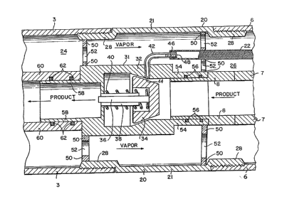
claims. For example, as shown in Figure 8~ an altern-
ative embodiment of the invention may include a pump
means for non-coaxial product and vapor hoses, whereby
a rigid housing 140 installed between the nozzle 141,
product hose 142 and vapor hose 143 includes a venturi
pump 144, similar to venturi pump~64, located in the
fuel flow and a vapor flow path 145 or passing vapor
from the nozzle 141 to the vapor hose 143. A rigid
tube 147 located in the vapoe flow path 145 connects
the venturl pump throat opening 14~ with a flexible
tube 143 which terminates at an area of the vapor hose
143 where fuel is expected to accumulate. A check
valve and filter assemhly (not shown) similar to the
, ~ ..
~;~7~
- 13 -
check valve and filter assembly 102 used with venturi
pump 64 is installed in a suitable location between the
venturi pump throat opening 146 and the flexible tube
148.