Note: Descriptions are shown in the official language in which they were submitted.
~;Z'7~i~5;;~
This invent-lon relates to mechanical seals for rotating shafts, and
a method o~ making such seals.
Packing seals and mechanical seals are two types of seals used to
prevent leakage around a rotating shaft.
The prior art packing seal consists of packing material wrapped
around the shaft and compressed so as to provide a tight fit against it. As
the packing seal is stationary while the shaft rotates, the seal places a
great deal of drag on the shaft and will wear the shaft away o~er a period
of time. The worn shaft must then be replaced at considerable cost.
The prior art mechanical seal overcomes some of the packing seal
drawbacks. These prior art mechanical seals fit over the shaft, and a
driver of the seal is held thereto by set screws so that the driver rotates
~ith the shaft. The area between the shaft and the seal is sealed by
conventional means, e.g., O-rings, while the flow path around the outside of
the mechanical seal is closed by forcing a thin graphite lip of a seal
portion of the mechanical seal against a stationary ceramic collar mounted
around but not connected to the shaft. Because of the high speed of
rotation of ~he shaft and the seal, the continual pressure of the seal
against the ceramic collar, and the high temperature to which the seal is
9~L~9~ >~ æ~2~ æ~ Qt~
b~` D.~S s~c~ as p~s'c~c Or p~sti~ ~a~ e
o~v.ce a sea~ ~-c-~or~; e~,~ t~ ~e ~ase~, a~ acco~O~y ~ t~e p~o~ ~c~: se=~
is usua~L~y ~ entire~y o~ ste~, e~cep~ ~o~ t~e s~a~ ~ra~h~e ~p. As
a result, the prior art mechanical seals are very expensive, wh~ch expens~
i~ increased 1~ the seal mus~c ~e specially :~abricated Eor a non-stan~ar~
size shaf~. Furthermore, some liquids, e.g., some acids and salt water,
~ill attack steel and other metals, and for those applicati~ns~ a packing
:
-- 1 D, i~
:: .; ...... -
52
2 60412-1391
seal must be used insteadO
Another drawback is that the set screws, which hold the
prior art mechanical seal in place, dimple the shaft. If a
packing seal is later used on the same shaft, the dimples will
tear up the packing material as the shaft rotates.
It has been discovered that an improved mechanical seal
can be made by injection molding a driver of the seal from a
compound according to the present invention and as described in
greater detail herein below, the resulting parts having
substantial strength and very similar coefficients of expansion.
According to one broad aspect of the present invention,
there is provided a mechanical seal comprising a driver, a seal
portion, and means for attaching said driver to a shaft,
characterized in that said driver is injection molded from a
compound based on a polyphenylene sulfide resin combined with
carbon.
According to a second broad aspect of the present
invention, there is provided a mechanical seal comprising a driver
and a seal portion, said seal portion being injection molded from
a compound that is between 10% and 20~ phenolic resin with the
remainder being mostly graphite powder.
In the preferred embodiment, the driver portion is made
of a mixture of 60~ of a compound based on RYTON ~, a
polyphenylene sulfide resin, and 40% carbon filter, which mixture
is melted, forced into a mold heated to a temperature of 300 F,
and then solidified. The seal portion is made of a mixture of 90
graphite powder and 10% phenolic resin, which mixture is also
Trade-mark
76~3S~
-2a- 60412-1391
compression molded to a carbon lip which acts as a sealing face
when the ~seal is in operation. Both the driver and seal portion
are then post-cured at temperat~res of ~00 F and 350 F
respectively for a period of hours so as to cross-link the
molecules to create a stronger bond between them and give added
strength to the parts. The clamping means for the preferred
embodiment comprises a series of separate fingers on the driver,
all of which are engaged by a split collar, which when attached,
compress all the fingers against the shaft.
In another preferred embodiment, the seal portion and
the lip are
: ~'
:
a~7~5~
both compression molded out of the graphite and resin compound, and the
clamp has a sloped interior wall that grasps but does not dimple the shaft.
~ e now turn to a description of the preferred embodiments, after
~irst briefly describing the accompanying drawings.
Figure 1 is a perspective view of a mechanical seal of this
invention;
Figure 2 is a cross-sectional view of a mechanical seal of this
invention mounted on a pump shaft;
Figure 3 is an enlarged perspective view of a driver of ~he seal
of one embodiment of the invention;
Figure 4 is an enlarged perspective view of one embodiment of a
clamp of the driver;
Figure 5 is an enlarged perspective view of one em~odiment of the
seal portion of this invention;
Figure 6 is an enlarged perspective view of a simplified mold for
the parts of the mechanical seal of this`invention;
Figure 7 is an exploded view of the preferred embodiment of this
invention; and
Figure 8 is a partial cross sectional view of the preferred
en~odiment.
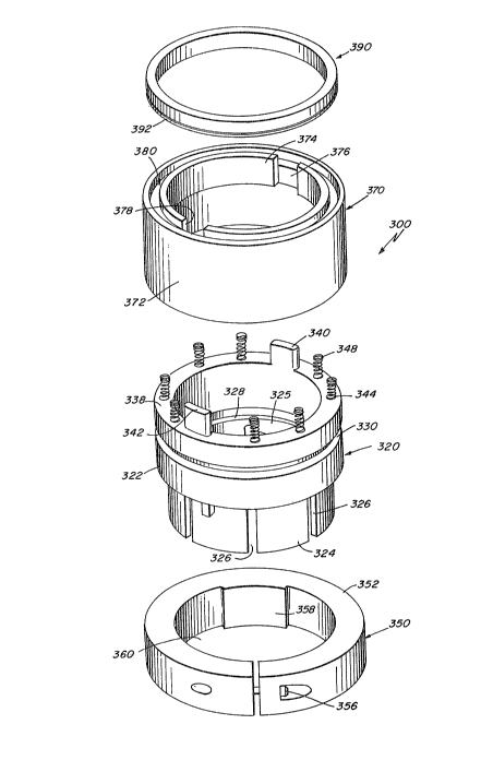
Referring to Figures 7 and 8, the preferred embodiment of a
mechanical seal of this invention is shown at 300. The seal 300 generally
comprises a driver 320 and a seal portion 370.
As shown best in Figure 7, the driver 320 comprises a cylindrical
wall 322 having a series of five long fingers 324, and a truncated finger
325 extending downwardly therefrom. The fingers are curved to fit around
the shaft ~not shown) to be sealed, and they are separated by gaps 326 about
~76~
60 apart. A first annular 0-ring groovc 328 ls disposed around the interior
of the wall 322, and a second annular 0-ring groove 330 is disposed around
its outside. A top surface 338 of the driver 320 has a pair of tabs 340, 3~2
extending upwardly therefrom. The tabs 3~0, 3~2 are positioned 180 apart.
A series of spring holes 344 are disposed in the top surface 338.
The driver 320 is injection molded in an integral piece of a
compound which is primarily carbon and resin. As will hereinafter be
explained, the injection molding is done so that all or almost all of the
various parts of the driver 320 are integral. This is because any machining
of the resin will cut away at least a portion of the resin-rich outer
surface, which results in a weaker ~more bri~tle) part. Accordingly, any
machining should be kept to a minimum.
The base resin used is BR-31 ~Ryton ~ ) from Phillips Chemical
Company of Houston, Texas. The BR-31 is a polyphenylene sulfide resin, but
unlike other polyphenylene sulfides, parts from this particular type of
polyphenylene sulfide have more durability without internal cracking due to
differen~ial shrinkage. Also, this particular resin is not corroded by most
acids or other corrosion-inducing liquids, erg., salt water.
The base resin is then turned into a ccmpound. Initially, a sheet
of the base resin is formed, and carbon fibers, which are chopped strands
about 1/~ inch long, are pressed onto the top surface of the sheet. Usually,
a resinous, phenolic blend of sizing is first applied to the carbon fibers to
aid the fibers compatability with the base resin and to make handling of the
fibers and molding easier. As the carbon fibers are distributed evenly over
the surface of the sheet, the sheet is then cut into small chips, each of
which has the same percentage of carbon an~ resin. In the preferred
Trade Mark
_ ~ _
~6~SZ
embodiment, carbon is about 40% of each chip by weight.
The chips of the carbon and resin sheet are fed into an extruder
and melted at temperatures between 575F and 675F. The total dwell time
is five minutes, as any longer will adversely af~ect the material. The
resulting strands from the extruder are chopped into pellets for further
compounding, which involves adding a number of other materials. In the
preferred embodiment, fiberglass (chopped 1/4 inch strands of E type glass)
is added aftar being treated with a silane coupling agent which aids in
obtaining a strong bond between the fiberglass and the rest of the compound.
,10 Concentrated pellets of polyphenylene sulfide with a black dye pigment are
also added, along with a micro-fine channel black and a coarser bone black.
These carbon blacks are added in equal amounts. Calcium metasilicate ~a
high purity grade of Wollastonite ~ ) and calcium stearate (molding grade)
are also added.
In the preferred embodiment, the B~-31 resin amounts to between 50%
and 75%, of the compound-by weight, and generally is about 60% or somewhat
less. The carbon fiber is between .25% and 50% of the compound by weight, and
generally is about 40% or somewhat less. Preferably, the fiberglass is
usually about 5% by weight, although it may constitute as much as 50% of the
total. The silane coupling agent is .25% to 2% of the fiberglass by weight,
and the sizing is between 2% and 5% of the carbon fiber by weight. The
carbon blacks (both together) and the calcium metasilicate are all .25% to 5%
of the resin by weight, while the pigment is between .25% and 4% of the resin
by weight, a~d the calcium stearate is between .25% and 2~ of the resin by
weight.
In addition certain other fib~cus and non-fibrous
Trade Mark
-- 5 --
- ~7~5;~
reinforcements may be used in the compound. These include boron, asbestos,
polybenzimidazole fiber ~a]l fibrous), and talcs, glass microspheres, clays,
calcium carbonate, TEFLON ~ and other carbon blacks ~all non-fibrous).
When the additives have been blended together, this carbon and
resin compound is kept tumbling and drying in an air-circulating, heated
hopper to exclude moisture until the compound is ready for injection molding.
The pellets of the carbon and resin compound are then injected into
a mold by feeding the pellets into the screw of the machine through which
they are moved through a barrel heated to 500F to 600F (nozzle temperature)
in steps of 20F or 50FJ depending upon the number of heating zones. The
injection pressure is 150 pounds when using a Trueblood 110 ton machine, and
the mold itself is initially heated to 300F + 10F. This mold heating is to
assure that the liquified compound will flow through the entire mold and
fill it completely. A reduced mold temperature, e.g., under 250F, is not
desirable, as the appearance and physical properties of the resulting driver
may be adversely affected, and an uneven mold temperature may mean that all
the cavities will not fill completely. Accordingly, the mold heating rods or
oil passages (not shown in Figure 6) must also be located around the extreme
mold areas and any other areas which may fill slowly or last to hold
temperature throughout the mold at 300F _ 10F for the filling process. The
mold itself must be vented, contrary to the usual venting in the prior art
thermoplastic molding processes, to eliminate all interior gases, the presence
of which might cause the resulting part to have varying densities or
blowholes, both of which are potential sources of stress failure.
As shown in a simplified mold 200 for this invention of Figure 6,
mold venting is accomplished in two unconventional ways. First, in the usual
Trade Mark
-- 6 --
~76~Z
molding process~ round ejector pins are used to aid in removing the finished
product from the mold. In moulding a circular ring or a cylinder, four or so
pins would usually be located symmetrically around the bottom (bottom edge
in the case of a cylinder), and would force the piece up out of the mold when
the piece had hardened. ~ith this invention, ejector pins 202 are flattened,
at least where they enter round holes 204 for them in ~he bottom of the mold
~00, so that air and other gases can escape from the mold by the flattened
pins. Secondly, there are at least four~and many more if the piece is
relatively large, e.g., a 6" diameter cylinder or ring) venting ports 206
spaced symmetrically around the outside of the mold. These ports 206 are
located around the top of the mold 2Q0 opposite the ejector pins 202, and
the ports 206 are typically 1/4" wide and .004" high. At least one
additional port(none shown)is placed in the areas where there may be
particularly significant gas build-up in the mold, e.g., deep grooves, holes
and undercuts. The additional ports would be placed on the edges of such
areas.
Also~ to fill the entire mold substantially at onceJ the mold 200
is filled using a 360 ring gate 208 (rather than a few individual conduits)
fed by a sprue 210, which is round and of highly polished steel with a
minimum length, has a taper of at least half an inch per foot. The ring gate
208 is usually about one third the thickness of the part to be made. The
ring gate 208 is attached to the mold at the top across from the vents 206.
In operation, the liquid compound flows through the sprue 210 and
into the ring gate 208, filling it. Once the ring gate 208 is filled, the
compound from the ring gate 208 then feeds into the rest of the mold
simultaneously around the entire 360 periphery of the ring gate 208. Gas
is forced out of the ports 206 and the portion of the holes 204 not covered by
~:7~ S;~
the ejector pins 202. The heating rods near the various cavities in the mold
assure that the cavities fill completely. When the mold is filled, water
is used externally to reduce the temperature of the mold and the liquid
therein, and the composition solidifies.
The driver 320 is then removed from the mold by use of the ejector
pins 202 and a reverse taper sprue puller ~not shown). The driver is then
post-cured for sixteen hours at 400F, and the post-curing improves the
strength of the driver and its mechanical and chemical resistance properties,
as it causes the molecules of the driver 320 to become cross-linked thereby
forming very strong bonds between them. It also increases the operating
temperature at which the driver 320 will melt.
0-ring grooves 328, 330 and holes 34~ may be molded into the unit,
or the driver 320 may be machined after the post-curing step to form them.
In the latter case, the machining is done at non-critical stress points, and
therefore the part is not weakened substantially. Also, it is necessary
to remove the material solidiied in the gate area as well as any material
extending from the ports or the ejector pin holes. Post-curing is again
performed after the machining operation.
The com~ound made for BR-31 resin is very suitable for this use
because it can be made into thick-section parts. Furthermore, unlike with
most other polyphenylene sulide and carbon based compounds, the resulting
part here is not brittle, but instead is highly flexible and can stretch. Thus,
the part is much tougher than previous PPS-carbon parts. Also, the BR-31 is
highly heat resistant, and the part made from the compound can withstand 500F,
which is the desirable upper limit for most mechanical seals (i.e., most
usual mechanical seal applications involve flows of 300F, which means that
that is the minimum temperature applied to the seal, as pump operation will
- 8 -
3~2'~
raise the temperature of the seal higher than that of the flow itself).
Other known res;ns could be used in the compound, but strength, temperature
and corrosion characteristics would be somewhat less and unsatisfactory or
some applications.
In order to complete the driver 320J rubber ~-rings not shown are
inserted into the O-ring grooves 328, 330, and springs 348 are placed in
each spring hole 344. The top half of the springs 348, all of which require
about thirty-six pounds to compress, extend above the top surface 338 of *he
driver 320.
As best shown in Figure 7, a clamp 350 is provided for the fingers
324 of the driver 320. The clamp 350 is actually a split ring 352, which is
secured together by a screw 356. A projection 358 extends into the inside
opening 360 formed by the rings. The projection 358 covers about 60 of the
circumference.
The seal portion 370 is best shown in Figure 7. Seal portion 370
generally comprises a cylindricaI sidewall 372, the inner diameter of which is
slightly greater than the outer diameter of the sidewall 322 of the driver 320.
Sid~wall 372 has an inwardly disposed flange 374 around its top, and a pair
of tab slots 376, 378 are disposed in thc flange 374, 180~ apart. A seal lip
groove 380 is disposed in the top surface of the sidewall 372. Groove 380
is offset from the edges of sidewall 372. A sealing lip 390 is also shown in
Figure 7. The lip 390, which forms the seal face for the mechanical seal 300,
is commercially available an~d is almost all carbon with some filters or binders.
The lip 390 has a small V-shaped groove 392 around its outer wall.
The seal portion 370 and the lip 390 are attached in the molding
process for the seal portion 370, which is made of graphite powder and phenolic
resin. The graphite powder, which is g9% pure carbon, is mixed with the
~2 7~S;~
phenolic resin. The resin makes up about 10~ of the total mixture, although
up to 20% resin is also satisfactory. The lip 3~0J after machining to proper
tolerance is manually positioned in the mold and pre-heated to 200F. The
carbon resin mixture is then injected into the mold, and compression molded
into the shape of the seal portion 370. The pressure used may vary between
5 and 100 tons. When the seal portion 370 has been formed, it is molded
to the lip 390 and the compound in the lip groove 392 prevents the lip from
pulling free. The injection molding machine uses a sensitive low pressure
closing system to eliminate damage to the lip when the mold ts closed. The
seal portion is then post-cured at 350F for four hours and the lip face may be
machined again. As with the driver 320, the post-curing cross-links the
molecules, making the part stronger and improving its temperature resistance.
As shown in Figure 8, the seal portion 370 is placed over the top
of the driver 320. The driver tabs 340, 342 slide into the tab slots 376,
378 which assure that the seal portion 370 will rotate with the driver 320,
and the top of the springs 348 contact the underside of the seal portion
flange 374.
The clamp 350 fits over the bottom portion of the fingers 324,
with the projection 358 fitting in the space crea~ed by the truncated finger
324 so as to prevent rotation of the clamp with respect to the driver 320.
The assembled seal 300 is slipped over a shaft (not shown). The
dimensions of the seal are such that the inner diameter of the driver 320
its fingers 324, 325 and the seal portion flange 374 are only slightly larger
than the diameter of the shaft. As these seal parts are molded, exact-fitting
seals for odd-sized shafts can be easily and inexpensively made. The seal
300 is sealed to the shaft by an 0-ring ~not shown), and 0-ring 377 prevents
any leakage between the driver 320 and the seal portion 370. The seal 300
- 10 -
~:76~5Z
is held in place on the shaft by clamp 350. Tightening the clamp screws 356
independently compresses the ingers 324 against the shaft over almost 360,
and the seal 300 is held firmly in place without dimpling the shaft.
The driver 320 is subject to more stress than the seal portion
370, and it is somewhat s~ronger. Nevertheless, the coefficient of expansion
of the driver 320 and seal portion 370 are almost the same so no leakage results
~hen the parts expand due to use in a high temperature liquid. Also, the
driver and seal portion have a substantial resistance to corrosion and high
temperature.
Referring to Figure 1, another mechanical seal according to ~his
invention is shown at 10, and as in the preferred embodiment, the seal 10
generally comprises a driver 20 and a seal portion 60.
As shown in Figure 3, the driver 20 comprises a cylindrical sidewall
22 having a semi-circular flange 24 extending around half of its lower end
26, Flange 24 has a pair of flat faces 28, 30 which are 180 apart, and
screw-threaded holes 32, 34 extend through faces 28, 30 respectively. Each
hole 32, 34 extends to open through ~not shown) the side of flange 24. An
annular 0-ring groove 36 is disposed around the inside of the sidewall 22 at
its approximate midpoint. A top surface 38 of the driver 20 has a pair of
tabs 40, 42 extending upwardly therefrom. The tabs 40, 42 are positioned
180 apart, and ten spring holes 44 are disposed in the top surface 38. The
driver 20 is injection molded in the same manner as with the preferred
embodiment. 0-ring groove 36 and holes 32, 34 and 44 may be molded into the
unit, or the driver 20 may be machined after the post-curing step to form them.
As with the preferred embodiment ~he machine is done at non-critical stress
points.
~L~76~5~2
In order to complete the driver 20, rubber 0-ring 46 is inserted
into the 0-ring groove 36, and springs 48 are placed in each spring hole 44.
The top half of the springs ~8, all of which require about thirty-six pounds
to compress, extend above the ~op surface 38.
As best shown in Figure 4, a clamp 50 is provided for the lower end
26 of the driver 20. Clamp 50 is generally a half-ring having a pair of
screw holes 52, 54 at its ends. Inner wall 56 of clamp 50 is angled
slightly, about 1.5, ~the angle sho~m in Figure 4 is exaggerated), and when
the clamp 50 is in place in ~he driver 20, the narrowest portion of the wall
56 i5 disposed towards the upper end of the drlver 20. Screws 58 hold clamp 50
in place on driver 20. As torgue is applied to the screws 58. ~he clamp
material is compressed so that-the entire inner surface of the clamp 50
contacts the shaft. Clamp 50 is made of the same material and in the same
manner as the driver 20, and as thermal expansion causes the shaft to grow,
so will the clamp 50, without loss of sealing area.
The seal portion 60 of this embodiment is best shown in Figure 5.
Seal portion 60 generally comprises a cylindrical sidewall 62, the inner
diameter of which is slightly greater than the outer diameter of the sidewall
22 of the driver 20, as shown in Figure 2. Sidewall 62 has an inwardly
disposed flange S4 around its top, and a pair of tab slots 66, 68 are disposed
in the flange 64, 180 apart. A seal lip 70 having a sealing face 72 extends
upwardly from the cylindrical sidewall 62 and the flange 64. Lip 70 is
offset from ~he edge of sidewall 62. Around the inside of the seal portion
60 at its opposite end is an annular 0-ring groove 74. 0-ring seal 76 is
placed in the groove 74 after the seal portion is made in the same manner as
with the pre~erred embodiment.
~7~52~
As shown in Pigures 1 and 2, the seal portion 60 is placed over
the top o~ the driver 20. The driver tabs 40, 42 slide into the tab slots 66,
68 which assures that the seal portion 60 will rotate with the driver 20, and
the top of the springs 48 contact the underside of the seal portion flange 6~.
A portion of a pump 100 is shown generally in Figure 2. The
pump 100 has a rotating shaft 102 and a ceramic collar 104 mounted around but
spaced apart from the shaft 102.
Assembled seal 10 is slipped over the shaft 102. The dimensions
of the seal are such that the inner diameter of the driver 20 and seal
portion flange 64 are only slightly larger than the diameter of the shaft 102.
The seal 10 is sealed to the shaft 102 by 0-ring seal 46, and 0-ring seal 76
prevents any leakage between the driver 20 and the seal portion 60. The
seal 10 is held in place on the shaft 102 by clamp 50. Tightening the clamp
screws 58 ~orces the angled wall 56 against the shaft from the posi~ion shown
in Figure 2, and the seal 10 is held firmly in place without dimpling the
shaft 102. This attachment is made close enough to the ceramic collar 104
so that the sealing surface 72 of the seal lip 70 is forced against the
collar 104. As the shaft turns, the lip 70 rotates while the collar remains
stationary, but as the lip 70 is mostly graphite, this interface is virtually
frictionless.
The lip 70 will eventually wear down with use, but because the lip
70, as well as the rest of the seal portion 60, has substantial strength, and
because the lip is longer than the effective length of the brittle graphite lips
of conventional seals, the seal portion of this invention has a much longer
useful life.
- 13 -