Note: Descriptions are shown in the official language in which they were submitted.
9~
The present invention relates to an apparatus for
heating the edges of an elongated rectangular metal object,
the edge portions of the object having the property of
cooling more rapidly than the central portions.
In particular, the present invention relates to a
means or apparatus for heating billets, strip or sheet-
metal, said means or apparatus including one or more
inductive edge heaters to heat the edges of a billet on i-ts
way from a continuous casting machine, or strip or sheet-
metal coming from a hot-rolling mill or pair, arranged to
surround the outer parts of the edges in order to heat them~
A similar device has been described in our
Canadian application 496,431, the heater(s) constituting one
or more ber}t, flat spiral elements (coils), arranged so that
the outermost parts of the edges will pass a greater portion
of the coil than parts located further from the edges, the
outer edge thus being heated more than the inner parts, and
that the edges are arranged to be heated to a temperature
corresponding approximately to that of the rest of the
billet, sheet, strip, etc.
The induction heaters are arranged to surround the
billet on three sides on its passage to a rolling mill, and
are suitably arranged to be supplied with single-phase mains
frequency or high frequency (1000-3000 HZ).
In processes where flat products are to be kept
hot along the production line, they cool more quickly at the
edges than in the rest of the product. Often the heating
means described above are sufficient. However, as is also
apparent from a study of temperatures from calculated
temperature distribution for slabs or other flat products,
sometimes a more complete compensation for the loss of heat
at the edges is required.
According to the present invention, there is
provided an apparatus for heating -the edges of an elongated
i.~
-- 1 -- ",~,
.~
6~
rectangular metal object, the edge por-tions of the object
having the property of cooling more rapidly than -the central
portions, the apparatus comprising a first induction heating
coil, the first coil being initially made in the form of a
flat, triangular coil, bent over two axes in said plane into
a U-shaped form, the width of the opening of the U-shaped
form being wider than the edges of the metal object and the
sides of the U-shaped form extending equally over both sides
of the metal object, and a second induction heating coil,
the second heating coil being flat in shape and positioned
in a vertical plane, substantially parallel to the adjacent
side surface of the metal object, and being of the same or
less width than the width of the opening of the first coil
after it has been bent to its U-shaped form, the second coil
being located adjacent to the first coil.
Preferred embodiments will now be described as
examples without limitative manner having reference to the
attached drawings, wherein:
- Figures la and lb show a typical temperature
ratio prior to the edge heating,
- Figure 2 shows a heater with combined coils,
- Figure 3 a side view of these heaters with a
side edge, and
- Figure 4 a heater with separate coils.
Figure 1 shows a typical temperature ratio prior
to heating. The means is intended to reduce the temperature
differences revealed in the figure.
In fig. la and lb, x is the distance from the
outer edge and b is the width. ~ T is the difference
between the mean temperature at various distances (x) from
the edge and the mean temperature at the centre of the
billet. x < b/2. After transport through the means, -the
energy supplied to the billet will be typically distributed
as ~ T.
~7~38~;
In such a means a substantially complete
temperature and heat-loss compensation will be obtained
along the edges of the flat billets to be further worked.
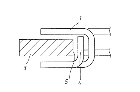
Figure 2 shows a triangular coil 1 surrounding a
side edge on three sides. The coil 1 is supplied with
single-phase (2) mains Erequency or high frequency (1000-
3000 H~). 3 is one side edge of a flat billet (Figure 3),
such as a slab or the like, which is thus surrounded on
three sides by the coil 1. The turns of the coil 1 are
wound triangularly so that the outermost parts of the side
edge 3 pass more turns of the coil than the parts located
further in ~see the above-mentioned patent applicatior.).
One or more vertical flat coils 4 are arranged in
series with or parallel to the coil 1, parallel to the side
edge and this or these coil(s) is/are arranged, together
with the coils 1, within the same roll gap.
The combination of a triangular coil 1 with a
vertical flat coil 4 at the edge sides 5 enables the
temperature of the edge and corners to be increased even
further.
The combination according to Figure 2 is thus
effected so that the triangular coil is placed in the roll
gap in a conveyor belt and the flat coil 4 in the same gap.
The space requirement for the heater in longitudinal
direction is thus limited.
Instead, the triangular coil 6 may be located in
an adjacent (or other) roll gap 7, while the flat coil 8 is
located in roll gap ~. See Figure 4.
The roll partition (7, 9) can then be kept shorter
than is the case according to Figure 1. This may be of
significance in the case of silicon steels, for instance,
which are malleable at working temperature.
In this application the supply sources for the
various coils (6, 8) may be separate, variation of the field
. . .
,. . ..
... .. ..
~ ,7Çj98~
strength and/or frequency being effected individually.
The means or apparatus according to the above can
be varied in many ways within the scope of the following
claims.
, . . ~ . ,. - . . . - ,..
,. - , ~: