Note: Descriptions are shown in the official language in which they were submitted.
7~
A HIGH R~PETITION ~ATE LASER SOURCE HAVING HIGH POWER
Technical Field
This invention relates to lasers and, in
particular, to laser sources which produce a stream of
pulses having high power at a hi~h repetition rate.
Background of the Invention
In optical communication systems, the speed at
which information is transmitted is limited by the pul~e
rate of the source. The pulse rate has been increased
to about 20 GHz by the use of mode-locking laser diodes.
Likewise, the clock rate limits the speed of
optical computing. Unlike optical communication
systems, however, the same mode-locked laser diodes
cannot be used alone to increase the clock rate in
optical computing. This is so because optical computing
requires, in addition to computing speed, high average
power to access a large number of parallel operations
simultaneously. The many separate logical elements must
be driven from a single clock source. The problem with
the prior art is the lack of a laser source which
produces high power pulses at a high repetition rate.
Summary of the Invention
The aforesaid problem is solved by
multiplexing laser pulses to a predetermined high
repetition rate and then amplifying the pulses by a
method known as injection mode-locking to boost the
power of the pulses to a predetermined level.
More particularly, in a first embodiment, an
oscillator produces a stream of laser pulses which are
spatially filtered, isolated and then mode-matched with
an amplifier. The mode-matched pulse stream is then
temporally multiplexed before being amplifîed to derive
the desired output stream.
The amplifier used in this invention differs
from known regenerative amplifiers in many ways. First,
in this invention, a continuous wave (cw) pulse stream
~ ~7~8
-- 2
is injected into the amplifier cavity to derive an
output pulse stream of about 22 GHz. In known
amplifiers, a single pulse is injected into an amplifier
cavity and then dumped out at the rate of 1 kHz.
Whereas known regenerative a~plifiers have elements
which suppress lasing be~ore the single pulse is
injected into the amplifier cavity, e.g. Q-switching
amplifiers, the amplifier of the present invention needs
no such special equipment. In this-invention, no
special equipment is needed. In known amplifiers,
expensive equipment, such as Pockels cells, is needed.
In a second embodiment of this invention, a
laser diode and a mode-matching lens are used to
generate the aforesaid predetermined high repetition
rate of laser pulses which is then amplified in the
aforesaid novel injection mode-locking amplifier to
derive the predetermined level of power.
Solid state lasers such as Nd:Y~G and Nd:YLF
are used because of their ruggedness, ease of operation
and high average power.
This invention is advantageous over the prior
art because a source of pulses is provided at a high
repetition rate in the order of 22 GHz and a high power
level of about 10 watts. This source is essential in
optical computing because the high repetition pulse rate
provides the high clock rate and the hi~h power provides
access to a large number of parallel operations at once.
This invention will find use also in
communications applications because it will provide a
high repetition rate source of coherent near Fourier
transform limited pulses. For coherent optical
communications schemes, the chirped non-Fourier
transform limited operation present in the distributed-
feedback diode lasers used is a detril~ent. A source
such as the present invention would provide a much more
attractive source at the same high repetition rate.
7~
Another use for the presen~ invention resides in
sampling systems such as electro-optic sampling which would
use the ultra-high repetition rate to average more shots and
as ~uch achieve even higher resolution.
In accordance with one aspect of the invention there
is provided apparatus for producing optical pulses comprised
of a source of optical pulses, said optical pulses occurring
at a first repetition rate, means coupled optically to said
source for pulsed stacking the pulses from said source to
~roduce a pulse stream at a second repetition rate, said
second repetition rate being greater than said first
repetition rate, and means into which said pulse stream from
said means for pulse stacking is injected for amplifying the
level of said pulse stream to a predetermined power level,
said means for amplifying including means for defining an
optical resonator and a gain medium positioned within said
optical resonator so that a cavity frequency is defined
therefor, said first repetition rate being integrally related
to said cavity frequency.
Brief DescriPtion of the Drawing
FIG. 1 shows one embodiment of the present
invention;
FIG. 2 shows a prior art regenerative amplifier; and
FIG. 3 shows a second embodiment of the present
invention.
Detailed Description
Referring to FIG. 2, there is shown a prior art
apparatus for producing a stream of pulses at a repetition
rate of about 100 MHz. The apparatus has a continuous wave
mode-locked Nd:~AG laser source 10 such as one made by the
Quan~ronix Corporation. Source 10 is sometimes called a laser
oscillator because short optical pulses at a relatively high
repetition rate are generated therefrom. Source 10 produces
pulses every 10 nano seconds (ns), each about 100 pico seconds
(ps) long. The stream of pulses from source 10 is selectively
refleated from 10% splitter 12 and one beam therefrom along
path 13 is reflected from 4% reflector 1~. The stream of
~L~
r~
~ "77~8
3a
pulses from reflector 14 is injected into regenerative
amplifier 20 after being reflected from element 16. The
stream of pulses ~7 is incident on polarizer 18 which is
located within amplifier cavity 20. Amplifier 20 is called a
regenerative amplifier. Regenerative amplifiers differ from
oscillators in that the power of a laser pulse, or a stream of
pulses, can be amplified by the former. See, for example,
FI5. 11.8 at page 147 of a book entitled, "Understanding Laser
Technology" by C. Breck Hitz, published by the PennWell Co.
~?,.~ ,p
'i`
~ ~77~
The light received within regenerative
amplifier 20 is passed through Pockels cell 22 and then
amplified by being bounced back and forth between the
two mirrors 2~ and 2~ via laser rod 26 which is
fabricated from Nd:YA5. Nd:YAG refers to a compound
comprising three parts of Yttrium, ive parts oE
Aluminu~ and twelve parts of Garnet which is doped with
trivalent Neodymium ions. See, for example, section
2.3.5 o~ a book entitled,'"Mode-Locking in Solid-State
and Semiconductor Lasers" by M. S. Demokan, published by
Research Studies Press. The stream of pulses which has
been amplified is then returned along paths 17, 15 and
29 to be used for any desired application in the prior
art.
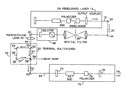
Referring to FIG. 1, there is shown a irst
embodiment of the present invention comprising laser
source 10. Source 10, similar to source 10 of FIG. 2,
is an oscillator which produces pulses at the rate, for
example, of about 100 ~Hz and 10 Watts. That is, source
10 is a continuous wave (CW) mode-locked Nd:YAG laser.
The output stream of pulses 31 from source 10 is
reflected at elements 32 and 34. There may be several
beams obtained from reflector 32 and directed to many
different regeneration amplifiers to be described below.
The reflected pulse stream from element 3~ is
filtered at spatial filter 36 and then passed through
isolater 38. Isolator 38 absorbs any reflection of the
pulse stream from elements downstream therefrom and
prevents the pulse stream from returning to laser source
10 so as to avoid damage thereto.
The stream of pulses from the output of
isolator 38 is then reflected by elemènt 40 into mode-
matching lens 42 which functions to focus the stream of
laser pulses from source 10 into reflector 52 which is
located within multiplexer 50.
~ ~7701~3
-- 5 ~
A novel feature of this invention comprises
the use of many serially located temporal multiplexers,
such as multiplexer 50, to increase the frequency of the
pulse stream ~rom about lO0 ~Hz, as in stream 31, to
about 22 GHz or any other desired high frequency.
Referring to multiplexer 50, there is shown a device for
multiplexing by pulse stacking using many beam
splitters. Thus, the pulse stream 43 which enters
splitter 51, a 50% splitter in this embodiment, is split
into two paths 51 and 53. The pulse stream 53 is
reflected at elements 54 and 56 and then returned to 50
splitter 58 where the two pulse streams are stacked, or
combined, to produce a pulse stream at twice, in this
embodiment, the frequency of the pulse stream which
enters multiplexer 50. The multiplexed pulse stream is
split at element 58 into two streams: a stream 59, the
use for which is not shown herein, and a second stream
61 which is multiplexed at other multiplexers, not shown
in FIG. l for convenience in drawing, similar to element
S0 to derive a desired frequency and then delivered
after reflection at element 62 to a high power high
regeneration laser source (HPHRL) 70.
Although HPHRL source 70 performs injection
mode-locking, there are some differences from a
traditional regenerative amplifier, such as the one
shown in FIG. 2. ~eferring to FIG. l again, first, the
pulse stream 63 is selectively received by reflector 72.
The received stream is then passed sequentially through
rod 74, which is selected from a group of materials
including Nd:YAG and Nd:Y~F, polarizer 76 and reflector
78. Reflector 78 selectively permits a predetermined
percentage of the pulse stream 77 incident thereon to
leave HPHRL source 7Q as the output pulse stream 79.
The stream of laser pulses derived from HPHRL source 70
has a repetition rate of about 22 GHz at about 10 Watts
in the preferred embodiment and finds use in optical
computing as the clock pulse. This is possible because
7~
-- 6 --
the high power of about 10 ~atts permit the clock to be
used for parallel operations.
An Nd:YAG rod 7g may provide pulses as short
as 10 ps. Even shorter pulses, such as one pico second,
S may be obtained by using Neodymium: Yttrium Lithium
Fluoride ~Nd:YLF) as the material for rod 74.
Several significant differences between HPIIRL
source 70 and regenerative amplifier 20 will now be
enumerated. HPHRL source 70 is a quasi continuous wave
source, that is, a steady continuous stream of pulses at
a high repetition rate, about 22 ~Hz, is produced. By
contrast, regenerative amplifier 20 o FIG. 1 provides a
single pulse at a rate up to about 1 kHz. Next,
regenerative amplifier 20 has internal cavity elements
to suppress lasing before the single pulse is injected
- and thereby Q-switches the amplifier. HPHRL source 70
does not require these elements. For Q-switching, see
for example, the aforesaid Hitz book at page 139 et seq.
Regenerative amplifier 20 requires an expensive Pockels
cell 22 to inject the source pulse into the amplifier
cavity and then to dump the output pulse after it has
been amplified from the cavity. HPHRL source 70 does
not require a Pockels cell.
As stated hereinabove, lens 42 performs mode-
matching. The repetition rate of source 10 is matchedwith an integral multiple of the cavity frequency of
HPHRL source 70. For example, a HPHRL cavity with a
round trip time of 10 nano seconds can be matched to a
source which provides a pulse every nano second. ~hus,
when provided with a pulse every nano second, HPHRL
source will support this pulse and give an output
equivalent to that input but with additional power.
There is a requirement on laser source 10 that
it produce pulses with a wavelength in the acceptance
- 35 range of HPHRL source 7Q. For HPHRL 70 with a Md:YAG
rod 74, source 10 should generate pulses with a
wavelength of either 1.064 micrometer or 1.3 micrometer.
7018
- 7 -
Referring to FIG. 3, there is shown a second
embodiment of the present invention. A stream of laser
pulses 83 are produced from a combination of laser diode
80 and mode-matching lens 82. Pulse stream 83 is
delivered to HPHRL source 70 which has been described
hereinbefore with reference to FIG. 1. The advantage of
the laser diode of FIG. 3 over the mechanism of FIG. 1
is that fewer elements are required for the laser diode
source. Furthermore, a laser diode source can be
fabricated to produce any high frequency pulse stream.
The power of the pulse stream, however, must be
increased from about as low as 10 femto joules to about
10 watts for optical computing.
There are advantages of using solid state
lasers such as Nd:YAG and Nd:YLF. These are their
ruggednes~, ease of operation and high average power.