Note: Descriptions are shown in the official language in which they were submitted.
BACKGROUND OF THE INVENTION
Field of the Invention
This invention relates generally to a monitoring
apparatus for training devices and more particularly to such
a monitoring apparatus which i5 adapted to select one of a
plurality of training devices and to monitor an audio signal
transmitted there~rom.
Description of the_Prior Art
In a so-called LI, (Language Laboxatory) system, in
order to permit an instructor or teacher to observe the
progress of many trainees or students, each of which is
trained in a booth provided with a respective training
device, the instructor monitors one by-one, for example,
through a pair of headphones or the like, audio signals,
such as, the pronunciation of various words or phrases by
the several trainees, transmitted from the respective booths
to a monitoring apparatus provided at a control desk for the
instructor. Such an apparatus is disclosed, for example, in
Laid-open Japanese Patent Publication No. 60-15076.
Fig. 1 shows a monitoring system according to khe
prior art, wherein tape recorders including respective audio
signal amplifiers All to Amn are located in N booths
arranged in a matrix having m rows and n columns, that is, N
= m x n. Audio signals, such as, the pronunciation of words
and phrases in a foreign language by the several trainees,
are collected by microphones M in the respective booths and
are supp}ied to the monitoring apparatus provided on the
control desk ~or the instructor. The monitoring apparatus
is shown to include audio signal input terminals
' '
' ~ ' ' ' " ' ' ' :
'.
34
,...,1 N and control circuits or switches 2 1,2 2~
...,2 N t each of which corresponds to a respective one of
the N booths. Output si.gnals from the control circuits
2 1,2 2,...,2 N are all supplied to a monitor amplifier 3,
and the output signal from the latter is supplied to a pair
of headphones HP through an output terminal 4 for monitoring
by the instructor. ~ shift register..9 is supplied with an
output signal from a pulse generator 11 through a selector
circuit 12, and respective output signals frem the shift
register are supplied to the control circuits 2 1,2 2~
2 N in an order according to a scanning command signal from
a scanning direction chanqe-over circuit 13. Such scanning
command signal is indicative of a desired scanning
direction, that is, the forward direction or backward
direction, so that the output signals from amplifiers Al1 to
Amn corresponding to the respective trainees are supplied
one by one to the monitoring apparatus. Thus, the
instructor can monitor, one by one, the progress of each
trainee. The monitoring apparatus according to the prior
art is further shown to have a manual scanning change~over
circuit 14 having a push button adapted to be momentarily
depressed for causing the pulse generator 11 to be
temporarily inhibited from generating its normal pulsed
output signal, and for causing. one scanning comm'and pulse
signal indicative of the forward direction or the ,backward
direction to be supplied to shift register 9 through
selector circuit 12 so that the instructor monitors the
trainee in the booth next to that which was previously
monitored. If the above-mentioned push-button is kept
--3--
. . . . .
,
, .
~27~;~
depressed, the period of inhibition of the output signal
from pulse generator 11 is made to be a predetermined period
of time by an output signal from change-over circuit 14,
that is, pulse generator 11 issues successive pulses with an
increased period therebetween, so tha~ the instructor can
successively monitor the several trainees one at a time for
the predetermined or increased period of time. -
By the way, in using the described lanyuagelaboratory system, a plurality of training programs are
prepared for trainees having different levels of skill, and
the tra,inees are classified into a number of groups, in
accordance with their respective skills or degrees of
advancement. The mGnitoring apparatus is provided with a
group selector switch and a program selector switch (not
shown), which supply the control circuits 2 1,2 2,...,2 N
with suitable control signals so that the instructor can
successively monitor trainees who belong to the same group
or who study the same program.
However, when the monitoring apparatus has its
control circuits 2 1,2 2,...,2 N supplied with various
control signals as described above, the control circuits in
the monitoring apparatus, as well as peripheral circuits
including the network between the control desk and the
several booths become complicated. Further, the number of
control keys is increased, so that the instructor's
operation of the control keys of the monitoring apparatus is
complicated and made difficult.
To solve this problem, it has been proposed that
the N booths be divided into groups by row or column, with
.
.
.~ - . . ~, , .
~7~
trainees in the same row or column having the same skill
level or degree of advancement, and thus using the same
study program.
In Japan, it is the tendency to arrange the booths
in groups by the column. Therefore, it is sufficient if the
instructor can monitor the trainees one by one in a selected
column.
On the other hand, in countries foreign to Japan,
the booths are, in many cases, grouped by row. It is
there~ore impossible to employ, in a country foreign to
Japan, an unmodified monitoring apparatus intended for use
in Japan. For this reason, at the time of manufacture, the
scanning direction for successive monitoring has to be
changed from the column direction to the row direction by
the use of a bit switch or the like provided in the
monitoring apparatus. Therefore, the monitoring apparatus
for use in Japan and those for export from that country,
must b carefully distinguished from each other during L
production and during preparation for shipping.
OBJECTS AND SUMMARY OF THE INVENTION
Accordingly, it is an object of the present
invention to provide a monitoring apparatus for training
devices which is capable of freely setting the scanning`
direction for successive monitoring to a selected one of :~
forward, backward, left, and right directions.
According to one aspect of the present~ inv~nti~on,
there i6 provided a monitoring apparatus for training
devices which comprises control switch means for selecting
audto signals output from a plurality of respective training
,
;. ' ' ' ' '~' ' .
.
~2~134
devices arranged in columns and rows and for obtain~g an
output signal to be monitored, scanning direction selecting
means for selecting a scanning direction from the directions
of the columns and rows, respectively, and coordinate step
advancing means operable in one of the column and row
directions in response to actuation of the respective
scanning direction selecting means for causing the control
switch means to successively select one-by-one the audio
signals output from the training devices which are
successively arranged in the selected column or row
direction.
The above, and other objects, features and
advantages of the present invention, will become apparent
from the following detailed description of a preferred
embodiment taken in conjunction with the accompanying
drawings, throughout which like reference numerals designate
like elements and parts.
: BRIEF D~SCRIPTION OF THE DRAWINGS
Fig. 1 is a block diagram showing a monitoring
apparatus for training devices according to the pxior art;
Fig. 2 is a block diagram showing a monitoring
apparatus for training devices according to one embodiment
of the present invention;
Fig. 3 is a ~low chart to which reference will be
made in explaining the operation of the monitoring apparatus
shown in Fig. 2;
Fig. ~ is a diagrammatic front view of a control
panel of the monitoring apparatus shown in Fig. 2; and
.. . .
:, ,, ' .
L3~L
Fig. 5 is a block diagram showing, in greater
detail, a circuit arrangem~nt included in the monitoring
apparatus of Fig. 2.
DESCRIPTION OF THE PREFERRED EMBODIMENT
Referring initially to Fig. 4 which shows a
control desk or panel of a monitoring apparatus according to
the invention, it will be seen that reference letters M~
designate a keyboard made up of monitor keys Kll to Kmn
corresponding to respective booths arranged in a matrix
which has m rows and n columns. If an instructor operates
or depresses a selected monitor ~ey Kij, he can monitor a
trainee who is in a corresponding booth at the intersection
of row i and column j. The monitor keys ~11 to Kmn are
provided with respective light emitting diodes (LED) Dll to
Dmn for indicating the booth selected to be monitored.
Reference numeral 20 designates a scanning direction
se~ecting keyboard ha~ing keys 21,22,23 and 24 actuable for
scanning in the forward, backward, left and right
directions, respectively. Reference numeral 30 designates a
tape recorder operating condition indicator panel which
shows the operating condition of the tape recorder axranged
in the booth being monitored. The tape recorder operating
condition indicator panel 30 comprises a rewinding indicator
LED 31, a stop indicator LED 32, a playback indicator LED
33, a fast forwarding indicator LED 34, a recording
indicator LED 35, and a drill (repeat training) indicator
LED 36. Reference numerals PSl to PS4 designate respective
training program selector switches.
.~
~,:
, . .
7--
.
.
.
,,' '' '' , ' ' :. . ,
~27~713~
~ s shown on Fig. 5, the monitoring apparatus
according to the invention includes a central processin~
unit (CPU) 40 which comprises a counter 41 and a timer 42.
The CPU 40 and a RAM 43 are both connected to a data bus 44.
A switch matrix 45 is provided with switches Sll to Smn
which correspond to the monitor keys Kll to Kmn,
respectively. If the selected monitor key Kij is depressed,
data corresponding to the x-coordinate (column number j) and
the Y-coordinate (row number i~ of a switch Sij associated
with the depressed monitor key Kij are stored in RAM 43
through an X-encoder 46X and a Y-encoder 46Y, respectively,
connected with data bus 44. Further, an LED matrix 47 is
: provided with the LEDs Dll to Dmn which are respectively
provided in the monitor keys Kll to Kmn, as mentioned above.
When monitor key Xij is depressed, the data provided by
encoder 46X and 46Y for the X-coordinate j and Y-coordinate
i of monitor key Xij are supplied through bus 44 to an
X-decoder 48X and a Y-decoder 48Y to cause illumination of
the LED Dij provided in the corresponding monitor key Kij.
An interface 49 is provided for designating a scanning
direction and generates key codes in response to actuations
of the keys 21 to 24, respectively. The selected key code
is supplied from interface 49 to counter 41 and timer 42 of
CPU 40. A decoder 50 connected with bus:44 supplies control -
switches 52 and 54, which will be hereina~ter described in
detail, wlth scanning control data obtained in response to
depressing of the selected monitor key Kij and one of
direction keys 21 to 24.
.
" . ' '
~' ' ' ' ' ' '
.
:: .
L3~L
Reference numera~s 511 to SlN designate audio
signal input terminals which respectively correspond to N
booths arranged in a matrix having m columns and n rows,
that is, N = m x n. The above-mentioned control sw.itch 52
has N fixed contacts which respectively correspond to the N
control circuits 2 1 to 2_N shown in Fig~ 1. The control
switch 52 is controlled by an output signal from decoder 50
and connects the monitor amplifier 3 selectively with one of
input terminal~ 511 to 51N~ whereby a pair of headphones HP
connected to output terminal 4 is supplied with an audio
signal from the trainee in a selected booth which is being
monitored by the instructor, and simultaneously the LED Di
of the depressed monitor key Kij corresponding to the
select~d booth, is lit~
The control switch 54 is supplied with data
indicative of the operating conditions of the tape recorders
arranged in the respective booths through input terminals
~31 to 53N. The control switch 54 is constructed in the
same manner as the above-described control switch 52 and is
associ~ted with control switch 52 to be operated with the
latter in response to the output signal from decoder 50 for
selectively connecting one of the input terminals 531 to 53N
with a decoder 55. An output from decoder 55 is supplied to
an operating condition indicator circuit 56 to indicate
operating conditions of the tape recorder in a ~elected
booth by lighting one of the indicator LEDs 31 to 36
situated on the panel shown in Fig. 4.
~ The operation of the monitoring apparatus
;~ according to the inven-tion will now be explained with
':
_ g _
.:
.. . . .
' :' '
~ ; ', ' . ' ', ' ' ' ' : ' "
.
' . , , . ,:
~ ' '. , ' '
reference to the, in some respects, more detailed block
diagram of Fig. 2, wherein, the same reference numerals are
used to identify parts already described with reference to
~igs. 1,3,4 and 5 so that further explanation thereof will
be omitt~d.
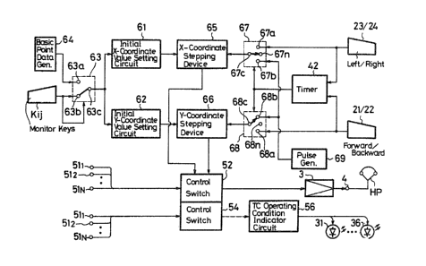
In Fig. 2, an initial X-coordinate value setting
circuit 61 and an initial Y-coordinate value setting circuit
62 having their inputs connected in common to a movable
contact 63c of a switch 63. One fixed contact 63a of switch
63 is connected with a basic point data generator 64 which
generates data corresponding to the coordinates (x = 1,
y = 1) of the monitor key K11 for the booth located at the
intersection of column 1 and row 1. Another fixed contact
63b of switch 63 is connected with a matrix switch Sij ~Fig.
5) represented by the respective monitor key Kij. If
monitor key Kij is depressed, switch 63 is actuated to the
state shown in Fig. 2.
Reference numerals 65 and 66 designate an
X-coordinate stepping device and a Y-coordinate stepping
device, respectively, which may be constituted by counters.
One input terminal of X-coordinate stepping device 65 is
supplied with an output signal from initial X-coordinate
value setting circuit 61 while the other input terminal
thereof is connected with a movable contact 67c o~ a switch
67. Similarly, one input terminal of the Y-coordinate
stepping device 66 is supplied with an output signal from
the initial Y-coordinate value settiny circuit 62 and its
other input terminal i5 connected with a movable contact 68c
of a switch 68. A first ~ixed contact 67a of switch 67 lS
--10--
.
.
~,
',, . . . '. ' :' ,
'. . . : : . :
- ' - ' ' , '
'. ' '
connected with scanning keys 23 and 24 for scanning in the
horizontal or left and right directions, and a second fixed
contact 67b of switch 67 is supplied with an output signal
from a pulse generator 69. A first fixed contact 68a of
switch 68 is connected with scanning keys 21 and 22 for
scanning in the vertical or up and down directions, and a
second fixed contact 68b of switch 68 is also supplied with
the output signal from pulse generator 69. The pulse
generator 69 may desirably be a frequency divider circuit
included in CPU 4 (Fig. 5) and having a suitable dividing
ratio. Output signals from scanning keys 21 to 24 for
selecting scanning in the respective directions are supplied
to timer 42 of CPU 40, and the respective output signal from
the latter is commonly supplied to both switches 67 and 68
as a control signal therefor. If none of scanning keys 21
to 24 are depressed, movable contacts 67c and 68c of
switches 67 and 68 are positioned to engage respective open
contacts 67n and 68n thereof, so that switches 67 and 68 are
both in a neutral state. However, i~ it is assumed that,
for example, scanning key 21 for effecting scanning in the
forward direction is depressed, movable contact 68c of
switch 6a is engaged with first fixed contact 68a. If
scanning key 21 is kept depressed for more than a
predetermined period of time, for example, ~or more than 1
second, a~ determined by timer 42, movable con~act 68c is
connected with second fixed contact 68b, as shown in Fig. ~.
Output signals ~rom the X-coordinate stepping
device 65 and Y-coordinate stepping device 66 are both
supplied to control switches 52 and 54.
,, -11-
,
~7~
Next, the operation of the monitoring apparatus
according to the invention will be explained with reference
to the flow chart oE Fig. 3.
If one of the scanning keys 21 to 2~ is depressed
for selecting scanning in the respective direction, that is,
the forward, backward, left or right direction, as in any
one of steps ~1) to (~), a code representative of the .
selected scanning direction is stored in a key memory, as in
the .respective one of steps (5) to (8). Then, it is
determined at step (9) whether or not a monitor key is
depressed. If it is determined that a monitor key Kij at
row i and column j of the monitor keyboard MK is depressed,
a scanning pointer is cleared in step (lO), data
representing the X-coordinate (column number j) and the
Y-coordinate (row number i) of the depressed key Kij are
stored in RAM 43 in step (11~, and initial values of the
X-coordinate and the Y-coordinate are respectively set to j
and i in st0p (12). If it is determined in step (9) that a
monitor key Kij is not depressed while one of the scanning
keys 21 to 24 is pr~ssed, the initial values of the
X-coordinate and the Y-coordinate are both set to "1" in
step (13).
After the initial values o the X-coordinate and
the Y-coordinate are thus set, the X-coordinate or
Y-coordinate of the scanning pointer i9 stepped or
incrsmented hy "1" in one of the four directions, that is,
the forward, backward, left or right direction, determined
by the scanning key 21 to 24 which is depressed, a~ in step
(14). For example, if the initial values are set to row i
.
-12-
, . . . ,: :
, ,
. . , , ~, ,
and column j, the selective depressing of scanning keys
21,22,23 and 24 will step the scanning pointer by 1 to row
(i+l), column j; row (i-l), column j; row i, column (j-l);
and row i, column (j+l), respectively. Further, if the
initial values are set to row 1 and column 1, depressing
scanning keys 21 and 24 for scanning in the forward and
right directions will shift the pointer to row 2, column 1,
or to row 1, column 2, respectively. If one of the scanning
keys 22 and 23 is depressed, the pointer will be shifted to
the last row and the last column, that is, the pointer is
shifted to row m, column 1, or to row 1, column n,
respectively.
Next, it is detected in step (15) by the use of
timer 42 whether the depressed scanning key 21,22,23 or 24
is kept depressed for more than a predetermined period of
time, for example, 1 second. For example, if forward
scanning key 21 i5 kept depressed for more than the
predetermined period of time, switch 68 is changed-over to
the state shown in Fig. 2, as described above, and then is
supplied with a pulse signal of a predetermined cyclic
period by pulse generator 69, whereby the Y-coordinate of
the scanning pointer is increased step by step until
scanning key 21 is released from its depressed condition.
Thus, booths arranged in the same column as that at row i,-
column j or at row 1, column 1, as set by the initial
scanning values, are successively monitored in step (16)~
When the booth at the end of such column is monitored,
monitoring returns to the first row in the same column.
Successive monitoring is effected in the same manner in the
-13-
.. . . . . . . . .
'
, . ,: :. .. . .
.
': ' ' ' ' '. "
~2`7~3~L
backward, left and right directions when scanning keys 22,23
and 24, respectively are held in the depressed condition.
The initial values of the X-coordirlate and the
Y-coordinate set as described above and the X coordinate and
the Y-coordinate values after the step-by-step incrementing
thereof are supplied to control switches 52 and 54 as
con~rol signals therefor, with the result that one of the
audio signal input terminals 511 to 51N and one of the input
terminals 531 to 53N for the booth corresponding to such
coordinate values are selected and connected to the
amplifier 3 and the tape recorder operating condition
indicator circuit 56. Thus, in step (16), the voice of the
trainee in the selected booth can be monitored by the
instructor through the headphones HP. Also, the operating
condition of the tape r~corder in the selected booth is
indicated by one of the indicator LEDs 31 to 36.
If the period of the pulse generated by pulse
generator 69 is set to a small value, for example, 0.2
seconds, operating conditions of the tape recorders in the
respective booths can be monitored, by observing the LEDs 31
to 36 turning on and off, for a short period of time.
In the above described embodiment of the
invention, the monitoring apparatus is provided with the
four scanning keys 21 to 24, each of which ls exclusively
used for causing scanning in one respective direction, so
that the instructor can easily manipulate the keys, the
sofkware for the computer can he simplified, and thereby the
reliability of the system iq improved.
.. . .
.. . . . . .
Also, since the instructor can successively
monitor trainees in the booths arranged in any of the four
directions, that is, forward, backward, left and right, the
monitoring apparatus can be the same for use in Japan and,
in countries foreign thereto.
Although a single preferred embodiment of the
invention has been described above with reference to the - -
accompanying drawings, it will be apparent that the
.invention is not limited thereto, and that many
modifications and variations could be effected therein by
one skilled in the art without departing from the spirit or
scope of the invention as defined by the appended claims.
~ 15-
:`
.
.
~' '. . .
, ' ' :.
,