Note: Descriptions are shown in the official language in which they were submitted.
127~
The present invention relates to a rail grinding unit
for grinding surface irregularities on a rail head of at
least one rail of a rallroad track having two rails, which
comprises a support frame having opposite ends, an
undercarriage having flanged wheels supporting each support
frame end on the rails for mobility along the railroad
track, a vertically adjustable carrier frame mounted on the
support frame, an endless grinding band mounted on the
carrier frame and trained about guide rollers under tension
for rotation thereabout, a lower one of the guide rollers
constituting a pressure roll for pressing the endless
grinding band into grinding contact with the surface, and
drive means for moving the endless grinding band about the
guide rollers.
U. S. patent No. 4,249,346, dated February 10, 1981,
discloses a continuously advancing rail grinding machine for
grinding surface irregularities on a rail head of a railroad
track rail. The machine has a sequence of tool carriers
with sliding whetstones as grinding tools. A crank drive
reciprocates the tool carriers to impart an operating
movement to the whetstones and the reciprocating operating
movement is superimposed on the continuous forward movement
of the machine to obtain a high grinding efficiency. The
patent also discloses an embodiment of a rail grinding
machine wherein the rail grinding tools are vertically
adjustable endless grinding bands trained about two guide
rollers arranged sequentially in the direction of the
track. A drive motor continuously moves the grinding band
about the guide rollers to impart an operating movement to
the grinding band which is superimposed on the continuous
:~
. ~ .
jr,~,
~l.Z~7~4Z
forward movement of the machine. This produces a high
grinding efficiency while producing high quality grinding of
the rail head surface.
- ~ustrian patent No. 221,131, of October 15, lg61,
discloses a rail grinding machine comprising a grinding unit
with a rail grinding band. The grinding unit is vertically
adjustably linked to the frame of the machine and is
supported on the track rails by flanged rollers. The rail
grinding band is trained about two guide rollers facing the
running surface of the rail head of a respective track rail
; and is then reeled over a drive crank. As soon as a section
of the grinding band in operating contact with the rail head
running surface is worn out, this grinding band section is
reeled over the drive crank to expose a subsequent grinding
band section reeled off a storage roll. The grinding
movement of the grinding band is provided only by the
forward movement of the machine and the grinding efficiency
is, therefore, very low while the operating life of each
grinding band section is very short because of the linear
contact thereof with the rail head surface.
European patent No. 0 110 2~6, whose grant was published
February 19, 1986, discloses a rail grinding machine which
is manually movable along one or both rails of a railroad
track. The machine comprises a grinding unit with a Erame
supported by flanged rollers on the track and an endless
grinding band trained over two guide rollers mounted
thereon. ~ carrier frame connected to the grinding band and
an actuating motor is manually vertically adjustable with
respect to the grinding unit frame by means of a screw drive
and is rotatable about a vertical axis. In addition, the
--2--
7 ~ ~ Z
carrier frame with the endless grinding band is manuall~
pivotal with respect to the grinding unit frame about an
axis extending in the longitudinal direction of the track to
incline the grinding band to a desired extent with respect
to the rail head. The machine may be removed from the track
on an outrigger equipped with rollers. Such a light,
manually operated machine has a low grinding efficiency and
is used only for spot grindiny, accurate surfacing being
impossible because of the manual operation. Coupling this
machine to a motor-driven car will not avoid these
disadvantages but will even cause additional down times to
permit intermittent manual adjustments. Furthermore, the
profiled pressure roll constituted by one of the guide
rollers extends far beyond the rounded edges of the rail
- head, which causes an excessive transverse curvature of the
grinding band, leading to a short operating life of the band.
It is the primary object of this invention to provide a
rail grinding unit of the first-described type which
produces a high grinding accuracy and uniformity over the
entire running surface of the rail head while operating at a
high efEiciency.
The above and other objects are accomplished in such a
rail grinding unit according to the invention with a
vertical adjustment device connected to at least one of the
grinding unit frames for ad~usting the depth of the grindiny
contact of the endless grinding band with the pressure roll
in relation to the rail head surface, the vertical
adjustment device including a remote controlled drive for
operating the vertical adjustment device.
This arrangement makes it possible to adjust the rail
.; .
'. : ; , ,
~27~ 2
grinding band accurately with respect to the rail head
surface to be ground so that a uniform and accurate grinding -
result is obtained, which avoids damaging overheating of the
rail head material adjoining the ground irregularities. If
the support frame is vertically adjustable in addition to
the grinding unit carrier frame, the grinding unit carrier
frame with the grinding band may advantageously be lowered
before the grinding operation is initiated into a zero
posi~ion in which the grinding band is just out of contact
with the rail head surface. Subsequent vertical adjustment
o the support frame with the grinding unit carrier frame in
its fixed zero position makes it possible to set the depth
of the grinding contact o~ the endless grinding band in
relation to the rail head surface with the desired
accuracy~ This accurate adjustment in relation to an exact
fixed position is of particular significance since the
grinding depth in a single grinding pass lies within a
relatively small range of only a few tenths of a millimeter. -
The above and other objects, advantages and features of
the present invention will become more apparent from the
following detailed description of certain now preferred
embodiments thereof, taken in conjunction with the
accompanying drawing.
FIGS. 1 to 5 are highly simplified, schematic side views
of five embodiments of a rail grinding machine and unit,
respectively, according to this invention, FIGS. 1 to 3
showing a machine ~rame and an undercarriage supporting
opposite ends oE the machine frame on the track ~or mobility
therealong, a vertically adjustable grinding unit being
;~ 30 arranged between the undercarriages at the opposite machine
.
. : . .. .
1~7~4Z
frame ends in the embodiment of FIG. 1, three like
sequentially arranged grinding units per rail being arranged
between the undercarriages in the embodiment of FIG. 2, a
rail planing machine preceding the rail grinding machine in
the embodiment of FIG. 3, FIG. 4 showing a grinding unit
with an endless grinding band trained over at least three
guide rollers and FIG. 5 showing a similar grinding unit,
with the lower guide roller being vertically adjustable to
function as a pressure roll;
FIG. 6 is an enlarged side elevational view of the rail
grinding unit schematically illustrated in FIGS. 1 to 3,
with an endless grinding band trained over a lower and an
upper guide roller;4
FIG. 7 shows a top view of the rail grinding unit along
lines VII-VII of FIG. 6;
FIG. 8 is a greatly enlarged, fragmentary cross section
of the lower guide roller constituting a pressure roll, as
shown in FIG. 6, the endless grinding band being shown in
the region of contact with the rail head surface to be
ground; and
FIG. 9 shows, in the right half, a section of the
grinding unit along line IX/l-IX/l of FIG. 6 and, in the
left half, a section along line IX/2-IX/2 of FIG. 6.
Referring now to the drawing and Eirst to FIG. 1, there
is shown rail grinding machine 1 for continuously grinding
surEace irregularities of a rail head of at least one rail
of railroad track 4 having two rails fastened to ties. The
machine comprises machine frame 2, undercarriages 3
supporting opposite ends of machine ~rame 2 on track 4 for
mobility therealong in an operating direction indicated by a
7~Z
double-headed arrow and drive 5 for moving the machine frame
along the track. Control panel 6 in an operator's cab on
the machine frame enable an operator to operate the various
machine drives. Grinding unit 7 Eor grinding the rail head ~ ;
surface irregularities is arranged between undercarriages 3
and comprises support frame 9 and undercarriages 8
supporting support frame 9 on track 4 between machine frame
undercarriages 3. Endless grinding band 10 is mounted on a
carrier frame vertically adjustable on support frame 9. The
rail grinding unit is illustrated in detail in FIGS. 6 to
and its structure and operation will be described fully
hereinafter in connection with these figures. Pulling rod
member 12 connects grinding unit 7 to machine frame 2 for
movement therewith. Preferably, a respective grinding unit
is associated with each track rail for grinding both rails
simultaneously as machine 1 moves along the track. Such a
machine operates at high efficiency because the continuously
rotating endless grinding band movement is superimposed on
the continuous forward movement of the machine. Vertical
adjustment drive means 11 connects grinding unit 7 to
machine frame 2. Cylinder-piston drives 11 mount rail
grinding unit 7 on machine ~rame 2 to lift the grinding unit
off the track when the machine is to be moved between
operating sites.
FIG. 2 schematically shows rail grinding machine 13 for
continuously grinding surface irregularities of a rail head
of at least one rail of railroad track 4 having two rails
fastened to ties. The machine comprises machine frame 14,
undercarriages 15 supporting opposite ends of machine frame
14 on track 4 for mobility therealong in an operating
--6--
7~
direction indicated by a double-headed arrow and a drive for
moving the ~achine frame along the track. Three like
grinding units 7 for grinding the rail head surface
irregularities are arranged between undercarriages 15
sequentially in the longitudinal direction of the railroad
track, each comprising vertically adjustable support frame 9
and undercarriages 8 supporting support frame 9 on track 4
between machine frame undercarriages 15. ~ndless grinding
band 10 is mounted on a carrier frame vertically adjustably
mounted on support frame 9. Pulling rod members connect
leading grinding unit 7 to machine frame 2 and the
succeeding grinding units to each other for movement with
the machine frame. Preferably, a respective series of
grinding units is associated with each track rail for
grinding both rails simultaneously as machine 13 moves along
the track. Such a machine with a sequence of grinding units
operates at a particularly high efficiency and, furthermore,
makes it possible to proceed with the grinding in stages by
using grinding bands of different coarseness. For example,
band 10 o~ leading grinding unit 7 may be the coarsest to
obtain rough grinding of the greatest surface irregularities
while the succeeding grinding units may have abrasive bands
of successively Einer grains to obtain fine grinding.
Respective vertical adjustment drive 11 connects each
grinding unit 7 to machine frame 14. Each grinding unit is
of the same structure and is operated in the manner as
indicated hereinabove in connection with FIG. 1.
The combination machine schematically illustrated in
FIG. 3 comprises rail planing machine 16 preceding rail
grinding machine 19 in an operating direction, planing
~277~
device 21 including vertically adjustable planing knife 20
for continuously planing the rail head before it is ground
by endless grinding band 10 on grinding unit 7 vertically
adjustably mounted on machine frame 22 of the rail grinding
machine by vertical adjustment drives 11. As in the
embodiments of FIGS. 1 and 2, the rail grinding unit is
supported by undercarriages 8 on railroad track 4 between
undercarriages supporting machine frame 22 on the track.
The rail planing machine has carrier frame 17 vertically
adjustably supporting the rail planing device and supported
by undercarriages 18 on the track. The rear end oE carrier
frame 17 is pivotally coupled to the front end of frame 22
of rail grinding machine 19. The rail planing device runs
on guide rollers on the track rails. The grinding unit of
the combined machine is operated in the same manner as
indicated hereinabove in connection with the description of
FIGS. 1 and 2. Such a combined machine is particularly
useful for working on heavily worn rails since the planing
device preceding the grinding unit is able to remove great
surface irregularities continuously by cutting them off the
rail head surface before the same is ground to its desired
profile.
In rail grinding unit 23 schematically shown in FIG. 4,
endless grinding band 26 is trained about guide rollers 24,
25 under tension provided by tension roller 27 arranged
; between upper guide rollers 25, lower guide roller 24
constituting a pressure roll for pressing endless grinding
band 26 into grinding contact with the surface of the rall
head to be ground. The guide rollers and the endless
grinding band are mounted on vertically adjustable carrier
:
--8--
~2~
frame 28, and vertlcal adjustment device 29 including a
rernote-controlled drive connects the carrier frame to
support frame 30. Undercarriages 31 support the opposite
ends of support frame 30 on the track, and cylinder-piston
drives 32 (like previously described vertical adjustment
drive means 11) vertically adjustably mount the grinding
unit support frame on the Eragmentarily illustrated machine
frame of a rail grinding machine, for example of the type
shown in FIGS. l to 3.
Rail grinding unit 33 schematically shown in FIG. 5
similarly comprises endless grinding band 36 trained about
- guide rollers 34, 35. The grinding band is held under `
tension by operating an adjustment drive vertically
adjusting the spacing between lower guide roller 34 and
upper guide rollers 35 wherebetween the lower guide roller
is arranged, lower guide roller 34 constituting a pressure
roll for pressing endless grinding band 36 into grinding
contact with the surface of the rail head to be ground. The
guide rollers and the endless grinding band are mounted on
vertically adjustable carrier frame 36, and a vertical
adjustment device 38 including a remote-controlled drive is
arranged between support frame 37 and undercarriages
supporting the opposite ends of support frame 37 on the
track, and cylinder-piston drives vertically adjustably
mount the grinding unit support frame on the fragmentarily
illustrated machine frame of a rail grinding machine, for
example of the type shown in FIGS. l to 3.
As shown in FIGS. 4 and 5, the two upper guide rollers
over which the endless grinding band is trained are mounted
on the carrier frame of the rail grinding unit sequentially
i.n the longitudinal direction of the rail in a vertical
,
~;277~g~2
plane and the pressure roll is arranged in this plane
substantially centrally between the upper guide rollers.
The pressure roll has a diameter larger than that of the
upper guide rollers, preferably twice as large as that of
the upper guide rollers. An endless grinding band trained
about at least three guide rollers will enable the grinding
unit to be constructed so compactly that it may be mounted
under a machine frame of a rail grinding machine in a space
of limited height, as may be the case in such rail grinding
machines with elongated machine frames. Where the pressure
roll is adjustable relative to the upper guide rollers, it
is possible accurately to control the grinding depth of the
~ band on a simple built support frame.
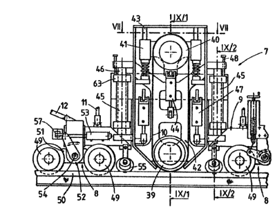
-~ FIG. 6 shows rail grinding unit 7 in detail. The rail
grinding unit comprises support frame 9 having opposite ends
~- and undercarriages 8 having flanged wheels 49 supporting the
opposite support frame ends on the rails of the railroad
track for mobility along the railroad track. Vertica:Lly
adjustable carrier frame 42 is mounted on support frame 9
and endless grinding band 10 is mounted on the carrier frame
and trained about guide rollers 39, 40 under tension, lower
guiding roller 39 being mounted on the carrier frame and
constituting a pressure roll for pressing the endless
grinding band into grinding contact with the rail head
sur~ace while upper guide roller ~0 constitutes a tension
roll holding the endless grinding band under tension.
Vertically displaceable yoke-like carriage 41 rotatably
bears tension roll 40 and vertical guide posts 43 are
mounted on carrier frame 42 in a longitudinal plane of
symmetry of endless grinding hand L0, the plane of symmetry
--10--
~Z~ L2
extending parallel to a vertical longitudinal plane defined
by the rail. Respective ends of carriage 41 are vertically
displaceably mounted on guide posts 43, and drive 44 is
connected to the carriage for vertical displacement
thereof. Vertical guides ~5 are mounted on support frame 9
at respective sides of grinding unit carrier frame 42, and
guide sleeves 46 on the carrier frame vertically dis-
placeably mount the carrier frame on the vertical guides. A
vertical adjustment device including remote-controlled
pneumatic drives 47 interconnects the support and carrier
frame for vertically displacing the carrier frame with
respect to the support frame. Set screws 48 are mounted on
the support frame for engaging the carrier frame to delimit
the vertical downward displacement thereof. The described
~- tensioning arrangement for endless grinding band 10 by
-.; operation of drive 4~ assures a constant and uniorm
tensioning of the band. The remote control of this drive
:.
makes it possible to relax the grinding band immediately
after the grinding operation has been completed, thus
enabling a quick replacement of the band. The symmetrical
vertical guidance of the carrier frame on the support frame
assures an exact and quick vertical adjustment oE the
carrier frame without danger of jamming to enab~e the
grinding band to be moved from an upper rest position to a
lowered operating position. Adjustment of the set screw
delimiting the downward movement oE the carrier frame makes
it possible to change the operating position of the grinding
band~ as may be required due to the wear of the band or
other operating factors.
Support frame 9 defines an upwardly extending recess
--11--
between the opposite ends thereof and, as shown, each under-
carriage 8 has a pair of flanged wheels 49 associated with
each rail and engaging rail head 50 thereof. Each under-
carriage comprises cradle 51 extending in the direction of
railroad track 4. Vertical adjustment drive 52 (similarly
to above-described device 38) is arranged between a
respective support frame end and undercarriage ~ at the
associated frame end, the vertical adjustment drive
comprisiny pivotal crank shaft 54 extending transversely to
the railroad track and a remote-controlled drive is arranged
Eor pivoting the crank shaft so that support frame 9 with
grinding unit carrier frame 42 may be vertically adjusted,
i.e. support frame 9 is vertically adjustable as well as
~-~ carrier frame 42 being vertically adjustable on the support
frame. At the left side of FIGS. 6 and 7, the remote-
~: controlled drive is illustrated as a cylinder-piston drive.
As shown at the right side of these figures, a manually
operated spindle drive may be used at the opposite end of
the support frame for rotating the crank shaft of the
vertical adjustment device for support frame 9. This drive
may be used additionally to remote-controlled drive 53
and/or pneumatic drives ~7 for fine adjustment of the
vertical adjustment. The exact vertical displacement o the
support frame with the grinding unit carrier frame relative
to the supporting undercarriages enables a fine tuning of
the grinding depth. Since the carrier frame with the
yrinding band remains stationary during this support frame
adjustment, the grinding band will be vertically adjusted in
accordance with the support frame displacement stroke.
~0 Mounting the undercarriages on a crank shaft provides a very
simple and stable vertical adjustment enabling even the
-12-
... . . .
" ~ ' '
~7~
smallest vertical adjustments of the grinding band to be
made. Due to the cradle shape o~ the undercarriages,
vertical positioning errors due to undulations on the
running surface of the rail head will be minimized so that
such errors will not be copied by the grinding band.
As shown in FIGS. 7 and 9, support frame 9 of rail
grinding unit 7 comprises two support frame parts 61, 62
arranged mirror-symmetrically with respect to a long-
itudinally extending vertical plane of symmetry of the
railroad track. Each support frame part 61, 62 carries a
respective carrier frame 42 with guide rollers 39, 40 and
endless grinding band lO for continuously grinding
irregularities on the running surfaces o~ rail heads 50 of
both rails and has its own vertical adjustment device 52
with remote-controlled operating drive 53. A telescopic
guide system comprised of a pair of parallel telescoping
braces 56 interconnects the two support frame parts and
spreading drives 57 are connected to the telescopic guide
system for transverse displacement of the support frame
parts with respect to each other. Each support frame part
is pivotally mounted on a respective end of telescoping
braces 56 for pivoting about axis 58 extending in the
longitudinal direction of the track. Furthermore, the upper
ends of the support frame parts are linked by tie rods
carrying a turnbuckle 59 to a transverse rod interconnecting
telescopic braces 56. This enables each support frame part
with its grinding band to be suitably inclined with respect
to the associated rail head to assume a desired g~inding
position. This arrangement provides a simple and compact
grinding unit for simultaneously grinding both rails. The
-13-
~27'71~Z
spreading of the telescopic guide system for the two support
frame parts reduces any play between flanged wheels 49 of
undercarriages 8 supporting support frame 9 and the rail
heads because they readily adapt the unit to changes in the
track gage and press the flanged wheels against the gage
sides of rail heads 50, thus enhancing the grinding accuracy.
As shown in FIG. 8, pressure roll 39 has a transverse
profile corresponding to that of rail head 50, the pressure
roll profile reaching only to the rounded edges of the rail
head and being constituted by a flat arcuate curve of large
radius in conformity with the running face of the rail
head. The curved profile is delimited at both sides by
narrow cylindrical sections extending parallel to the axis.
This configuration of the pressing surface of roll 39 in
.~ ,
conformity with the configuration of the rail head to be
ground assures not only high-quality grinding but also
enhances the grinding efficiency and the operating life of
the abrasive band. Since the cylindrical edges of the
pressing surface causes the corresponding edges of grinding
band 10 adjoining the rail head at both sides also to extend
parallel to the rotary axis of pressure roll 39, the
grinding band will rotate smoothly and quietly even at high
rotary speeds.
In the illustrated embodiment of pressure roll 39, it
comprises circumferentially extending tubular body 60 having
the above-described profile and this tubular body comprises
a hard, elastically yielding material, such as a hard rubber
having a hardness of 70 Shore. As indicated by the arrows
in FIG. 8, this assures a uniform pressure of the pressure
; 30 roll against the grinding band. An elastically yielding
-14-
~L2~7~L~Z
material of the indicated hardness produces a long operating
life and a grinding accuracy assuring removal of even the
smallest surface irregularities.
As shown in FIGS. 6 and 9, flanges 63 connect the ends
of guide posts 45 for guide sleeves 46 of the carrier frames
to support frame 9. Each pressure roll 39 on respective
support frame part 61, 62 is rotatable by hydraulic drive 64
about axis 65 extending perpendicularly to the longitudinal
extension of the track for rotating each endless grinding
band 10. Guide rollers 55 are affixed to support frame
parts 61, 62 and are arranged for tangential engagement with
the gage sides of rail heads 50, which are not worn. The
guide rollers are rotatable in a plane enclosing a dihedral
- angle of about 10 to about 20 with a vertical plane of
symmetry of the rail. These guide rollers enable the
support frame parts with their grinding bands to be guided
accurately along the rail heads since they engage only a
section of the rail heads which is not worn and has no
irregularities.
The operation of rail grinding unit 7 illustrated in
FIGS. 6 to 9 will now be explained in detail in connection
with rail grinding machine 1:
As soon as the rail grindiny machine has reached the
operating site, vertical adjustment drives 11 are actuated
to lower rail grinding unit into a position wherein flanged
wheels 49 of undercarriages 8 of grinding unit support frame
9 engage rail heads 50 of railroad track 4. Thereupon,
drives 47 are actuated to lower carrier frame 42 until set
screws 48 engage support frame 9, the set screws being so
adjusted that endless grinding band 10 trained over pressure
-15-
.
.
~2~7~L~2
roll 39 is just out of contact with underlying rail head
50. This ls the zero position of the grinding band. The
desired grinding depth of abrasive band 10 is then adjusted
from this zero position by vertically adjusting the position
of support frame 9, which is accomplished by the remote
control of drives 53 of vertical adjustment device 52 to
rotate crank shaft 5~. This accurately adjusts the vertical
position of support frame 9 with respect to undercarriage 8
and thus the vertical position of carrier frame ~2 and
endless grinding band 10. At the same time, spreading
drives 57 are actuated to move support frame parts 61, 62
apart and to press tangential guide rollers 55 against the
- gage sides of rail heads 50, whi~h are not worn. This
assures an exact lateral guidance of the support frame
parts, regardless of surface irregularities on other
; portions of the rail heads, with respect to a longitudinal
vertical plane of symmetry of the rail. By turning
turnbuckle 59, each grinding band may be adjusted to a
desired inclination with respect to the associated rail
head. After these adjustments for the desired operation of
the endless grinding bands have been completed, hydraulic
drives 64 are actuated to rotate pressure rolls 39 and thus
to rotate endless grinding bands 10. As machine 1 is
continuously advanced along the track by drive 5, rotating
yrinding bands 10 will uniformly, accurately and effectively
grind the rail heads to remove surface irregularities
there~rom. The remote control oE drives 53 makes it
possible to operate a respective vertical adjustment device
~` 52 so that the sur~ace conditions of each rail may be taken
into consideration Eor the adjustment of a desired grinding
depth with respect to each rail.
-16-