Language selection

Search

Patent 1277283 Summary

Third-party information liability

Some of the information on this Web page has been provided by external sources. The Government of Canada is not responsible for the accuracy, reliability or currency of the information supplied by external sources. Users wishing to rely upon this information should consult directly with the source of the information. Content provided by external sources is not subject to official languages, privacy and accessibility requirements.

Claims and Abstract availability

Any discrepancies in the text and image of the Claims and Abstract are due to differing posting times. Text of the Claims and Abstract are posted:

  • At the time the application is open to public inspection;
  • At the time of issue of the patent (grant).
(12) Patent: (11) CA 1277283
(21) Application Number: 504741
(54) English Title: HIGH-SPEED ELECTROLYSIS CELL FOR PROCESSING STRIP- SHAPED MATERIAL
(54) French Title: CUVE D'ELECTROLYSE RAPIDE POUR LE TRAITEMENT DU FEUILLARD
Status: Deemed expired
Bibliographic Data
(52) Canadian Patent Classification (CPC):
  • 204/127
(51) International Patent Classification (IPC):
  • C25D 7/06 (2006.01)
  • B65G 49/04 (2006.01)
  • C25D 5/08 (2006.01)
  • C25D 17/00 (2006.01)
(72) Inventors :
  • BECHEM, WERNER (Germany)
  • MAY, JOHANN JOSEPH (Germany)
  • PETERS, HUBERTUS (Germany)
  • SCHNETTLER, ROLAND (Germany)
  • SOLBACH, WERNER (Germany)
  • WOLFHARD, DIETRICH (Germany)
(73) Owners :
  • HOESCH STAHL AKTIENGESELLSCHAFT (Germany)
(71) Applicants :
(74) Agent: MACRAE & CO.
(74) Associate agent:
(45) Issued: 1990-12-04
(22) Filed Date: 1986-03-21
Availability of licence: N/A
(25) Language of filing: English

Patent Cooperation Treaty (PCT): No

(30) Application Priority Data:
Application No. Country/Territory Date
P 35 10 592.5 Germany 1985-03-23

Abstracts

English Abstract


ABSTRACT
The invention relates to a vertical electrolytic
galvanizing cell for processing steel strips in which the strip
to be processed running from an upper deflection or flow roller
is led to a lower deflecting immersion roller and from there
to a further upper deflection or flow roller, the respective
descending and ascending strip portion to be processed being
subjected in a gap between vertically disposed anodes to the
electrolyte flow conducted in circulation at high speed against
the strip running direction. In such a galvanizing cell the
circulation of large electrolyte amounts using the minimum
possible pump energy is achieved in that the electrolyte flow
directed in each case in the gaps between the anodes against the
strip running direction is generated via liquid jet pumps
disposed directly in front or behind the respective gap inlet.


Claims

Note: Claims are shown in the official language in which they were submitted.


THE EMBODIMENTS OF THE INVENTION IN WHICH AN EXCLUSIVE PROPERTY
OR PRIVILEGE IS CLAIMED ARE DEFINED AS FOLLOWS:

1. A vertical electroplating cell comprising housing
walls with vertically arranged rows of soluble anodes, having
inner and outer surfaces, for depositing metal on metal strips
in which the strip to be processed descends from an upper
conductor roll to a lower deflecting immersion roll and from
there is guided upwardly to a further upper conductor roll, and
wherein the descending and ascending strip portions to be
processed are each located in an inner canal between said inner
surfaces of said vertically arranged rows of soluble anodes,
said anodes further defining outer canals between said outer
surfaces of said anodes and said outer housing, and wherein said
descending and ascending strip portions encounter an electrolyte
flow of high velocity which moves in the direction opposite to
the direction of strip movement, characterized in that inside
of the electroplating cell housing there are means for producing
four separate circulating flows of electrolyte such that in each
of the canals (6,8) receiving the strip portions (11,12) the
electrolyte flow is directed oppositely to the direction of
movement of the strip, and which flows in said outer canals are
driven by jet pumps and redelivered to the inner canals.
2. An electroplating cell according to Claim 1
further characterized in that in each of the four electrolyte


circulating flows, several jet pumps are arranged whose driving
jets (9,10) are all connected to a single delivery tube
(92,102), which driving jets move the electrolyte flow into
cylindrical mixing tubes (94,104) having slit-nozzle exit
apertures (91,101).
3. An electroplating cell according to Claim
further characterized in that in the region of the descending
strip run (11) within both of the outer canals a downwardly
directed electrolyte flow is created by a row of jet pumps,
which flow is deflected upwardly through slit-nozzle exit
apertures (91) below the anodes by a curvature in the
cylindrical mixing tubes and which flow is directed into the
said inner canal (6) with an upwardly directed velocity
component and which flow, at the upper part of the anodes (5),
moves through intermediate spaces between anode ends (51) with
the help of upper edges of the housing wall (45) for redelivery
to the jet pumps and an overflow trap is provided for the excess
amount of electrolyte which excess electrolyte is redelivered
to the driving jets (92) of the jet pumps by an external
circulating system.
4. An electroplating cell according to Claim 1
further characterized in that in the region of the ascending
strip run (12) within the two outer canals, an upwardly directed
electrolyte flow is created by a row of jet pumps, which flow,
with the help of upper edges of the container wall (46), moves
through intermediate spaces between the upper ends of the anodes


(71) and is delivered to a space above the inner canal, after
which the electrolyte flows through the canal (8) between the
anodes downwardly into the lower portion of the housing of the
electroplating cell under the influence of a low pressure
created in the lower portion of the housing by the jet pumps,
and an overflow trap is provided for the excess electrolyte
formed by the upper edge of the container wall (46) which excess
electrolyte is supplied to the driving jets (92) of the jet
pumps by an external circulating system.
5. An electroplating cell according to Claim 2
further characterized in that the region of the descending strip
run (11), within both of the outer canals, a downwardly directed
electrolyte flow is created by a row of jet pumps which flow is
deflected upwardly through slit-nozzle exit apertures (91) below
the anodes by a curvature in the cylindrical mixing tubes and
which flow is directed into the inner canal (6) with an upwardly
directed velocity component and which flow, at the upper part
of the anodes (5), moves through intermediate spaces between the
anode ends (51) with the help of upper edges of the housing wall
(45) for redelivery to the jet pumps, and an overflow trap is
provided for the excess amount of electrolyte which excess
electrolyte is redelivered to the driving jets (92) of the jet
pumps by an external circulating system.
6. An electroplating cell according to Claim 2
further characterized in that in the region of the ascending
strip run (12), within the two outer canals, an upwardly


Claim 6 Cont'd.

directed electrolyte flow is created by a row of jet pumps,
which flow, with the help of upper edges of the container wall
(46), moves through intermediate spaces between the upper ends
of the anodes (71) and is delivered to a space above the inner
canal, after which the electrolyte flows through the canal (7)
between the anodes and the strip downwardly into the lower
portion of the housing of the electroplating cell under the
influence of a low pressure created in the lower portion of the
housing by the jet pumps, and an overflow trap is provided for
the excess electrolyte formed by the upper edge of the container
wall (46) which excess electrolyte is resupplied to the driving
jets (92) of the jet pumps by an external circulating system.


Description

Note: Descriptions are shown in the official language in which they were submitted.


~7~33

The present invention relates to a high-speed electrolysis cell
for processing strip-shaped material.

The counter-flow cell is known from Canadian Patent No.
1,251,415.

This invention provides an apparatus for generating the required
high flow speed of preferably about 2 m/s in the region between
anodes and strip.

It is possible with this apparatus in electrolysis cells with
vertical strip guiding both with unilateral and bilateral
processing of for example steel strips to obtain a uniform and
high flow rate over the entire processing surface both with
soluble and with insoluble anodes.

This high flow rate can be achieved with the minimum possible
energy requirement in that a large amount of electrolyte is
independently circulated in the cell. With the apparatus
according to the invention the circulation of large amounts of
electrolyte using a minimum pump energy is achieved in that the
liquid jet injector principle is used. This makes i~ possible
for an amount of electrolyte 3 to 5 times the amount introduced
by pumping to flow in circulation. This increase in the amount
in circulation is due to the constructional form of the
injectors in the actual electrolysis cell.

To ensure that when using soluble anodes the upper liquid level
remains free for observation of the strip and the anodes, the
water jet injectors are installed, in the case of the ascending
strip, in the lower region of the cell behind the anodes. These
jet injectors generate an upwardly directed flow which, by
suitable formation of the housing and the upper anode neck, is
deflected and pressed through the space between the anodes


ï~7~
--3--
and the strip in such a manner that a downwardly directed flow
is formed. This downwardly directed flow is set in operation
in that, due to the water ~et injector pumps in the lower cell
portion behind the anodes, a partial vacuum builds up at the
lower end of the flow well. By this system a considerable
amount of the electrolyte is conducted by the
circulation.
The electrolysis cell is supplied with purified and
cooled electrolyte in that the necessary electrolyte amount is
supplied to the jet nozzles by a circulation means comprising
filter and cooler via a pump.
In the region of the descending strip run the jet
pump is inserted in such a manner that via correspondingly
formed slit nozzles it introduces the required amount of
electrolyte into the space between anodes and strip. The
upwardly pumped electrolyte emerges through correspondingly
formed anode necks from the region between anodes and strip
aterally and can partially flow off to a supply tank.
Accordingly, the present invention provides a
vertical electrolytic galvanizing cell for processing steel
strips in which the strip to be processed running from an
upper deflection or flow roller is led to a lower deflecting
immersion roller and from there to a further upper deflection
or flow roller. The respective descending and ascending strip
portions to be processed are subjected in a gap between
vertically disposed anodes to the electrolyte flow conducted
in circulation at high speed against the strip running


,~n,/rm
..~
. ~. - .. .
: - - .

'' ' ' ' ~

~7~33

-3a-
direction. This cell is characterized in that the electrolyte
flow directed in each case in the gap between the anodes
against the strip running direction is generated via liquid
jet pumps which are disposed directly in front or behind the
respective gap inlet.
- The invention will be explained hereinafter with the
aid of an example of embodiment illustrated in the drawings,
wherein:
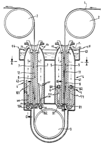
Fiy. 1 is a section in the longitudinal direction o~
the steel strip to be processed through a galvanizing cell,
Fig. 2 is a section along the line A-A of Fig. 1,
Fig. 3 is a section along the line B-B of Fig. 1,
Fig. 4 is a section along the line C in Fig. 1.
The galvanizing cell illustrated in Fig. 1 is
usually part of a system in which several such galvanizing
cells are disposed in series. The steel strip 1 to be
processed runs


rn/rm


' ` ' . ' ' ', ' .' ' ' ' .

.. . ...

~ Z~77;~3~

from the upper flow roll 2 with its descending strip section 11
in the gap 6 between vertically disposed anodes 5 centrally
through to an immersion roller 3 which is disposed in the
housing filled with the electrolyte. From this deflecting
immersion roller 3 the strip is led with its ascending strip
portion 12 again through vertically disposed parallel anode rows
7 in the correspondingly formed gap 8 to a ~urther upper flow
roller 2.

The anodes 5 and 7 are arranged with their surfaces facing the
strip parallel to the plane of the passing strip and removably
suspended at the upper anodes ends 51 and 71.

Formed around the anode pairs 5 is the housing portion 41 in
which an electrolyte flow is maintained in the direction of the
arrows. For this purpose, in the space between the housing wall
and the anodes, liquid jet pumps 9 are disposed whose mixing
tubes 94 are directed with their slit-nozzle-like ends 91
against the lower side oE the gap 6. In this manner with high
flow rate or high flow pressure an electrolyte flow can be
achieved opposite to the strip running direction and said flow
is usually kept turbulent and leads to optimum electrolysis
conditions ~or the passing strip portion 11.

The electrolyte amount overflowing at the ~op between the
electrodes 51 and the upper edges of the housing wall 45 flows
partially into the overflow trap 43 and from there is supplied
by an external system with pumps, filters, heat-exchanger unit
and the like to the jet pumps 9 again.

Provided around the anodes 7 in whose gap 8 the ascending strip
portion 12 is led, is likewise a separate housing portion 42.
The electrolyte flow maintained in this housing portion is also
indicated in its direction by arrows. The electrolyte is pumped


JJ:~ 4

~ Z7~83

into mixing tubes 104 and through the slit-nozzle-like ends 101
by jet pumps 10 thereby developing a region of low pressure in
the cell below the gap 8 between the anodes 7. The reduced
pressure creates a suction causing a large flow rate of
electrolyte downward in the gap 8 against the running direction
of the strip portion 12. The overflow emerging between the
anode ends 71 and the upper edges of the housing wall 46 again
flows into the overflow trap 43 and via the supply tubes 102 is
supplied by the interposed treatment system back to the jet
pumps 10. The corresponding supply tubes to the jet pumps 9 are
denoted by reference numeral 92.


JJ: 5
, : ,
.

Representative Drawing
A single figure which represents the drawing illustrating the invention.
Administrative Status

For a clearer understanding of the status of the application/patent presented on this page, the site Disclaimer , as well as the definitions for Patent , Administrative Status , Maintenance Fee  and Payment History  should be consulted.

Administrative Status

Title Date
Forecasted Issue Date 1990-12-04
(22) Filed 1986-03-21
(45) Issued 1990-12-04
Deemed Expired 2004-12-06

Abandonment History

There is no abandonment history.

Payment History

Fee Type Anniversary Year Due Date Amount Paid Paid Date
Application Fee $0.00 1986-03-21
Registration of a document - section 124 $0.00 1987-04-29
Maintenance Fee - Patent - Old Act 2 1992-12-04 $100.00 1992-11-16
Maintenance Fee - Patent - Old Act 3 1993-12-06 $100.00 1993-11-16
Maintenance Fee - Patent - Old Act 4 1994-12-05 $100.00 1994-11-17
Maintenance Fee - Patent - Old Act 5 1995-12-04 $150.00 1995-11-17
Maintenance Fee - Patent - Old Act 6 1996-12-04 $150.00 1996-11-15
Maintenance Fee - Patent - Old Act 7 1997-12-04 $150.00 1997-11-18
Maintenance Fee - Patent - Old Act 8 1998-12-04 $150.00 1998-11-19
Maintenance Fee - Patent - Old Act 9 1999-12-06 $150.00 1999-11-12
Maintenance Fee - Patent - Old Act 10 2000-12-04 $200.00 2000-11-17
Maintenance Fee - Patent - Old Act 11 2001-12-04 $200.00 2001-11-20
Maintenance Fee - Patent - Old Act 12 2002-12-04 $200.00 2002-11-19
Owners on Record

Note: Records showing the ownership history in alphabetical order.

Current Owners on Record
HOESCH STAHL AKTIENGESELLSCHAFT
Past Owners on Record
BECHEM, WERNER
MAY, JOHANN JOSEPH
PETERS, HUBERTUS
SCHNETTLER, ROLAND
SOLBACH, WERNER
WOLFHARD, DIETRICH
Past Owners that do not appear in the "Owners on Record" listing will appear in other documentation within the application.
Documents

To view selected files, please enter reCAPTCHA code :


To view images, click a link in the Document Description column. To download the documents, select one or more checkboxes in the first column and then click the "Download Selected in PDF format (Zip Archive)" or the "Download Selected as Single PDF" button.

List of published and non-published patent-specific documents on the CPD .

If you have any difficulty accessing content, you can call the Client Service Centre at 1-866-997-1936 or send them an e-mail at CIPO Client Service Centre.


Document
Description 
Date
(yyyy-mm-dd) 
Number of pages   Size of Image (KB) 
Representative Drawing 2001-08-14 1 17
Drawings 1993-10-14 3 109
Claims 1993-10-14 4 142
Abstract 1993-10-14 1 27
Cover Page 1993-10-14 1 23
Description 1993-10-14 5 168
Fees 1996-11-15 1 54
Fees 1995-11-17 1 86
Fees 1994-11-17 1 82
Fees 1993-11-16 1 40
Fees 1992-11-16 1 50